YCAG-安装操作维护手册
YCAG产品培训

454...846922
454...933274
54..485357
54..679615
544...384896
554...067284
3.6 235341% 32586% 253816%% 243197% 253715% 35178% 243496% 335928%% 3.6
YCWF012 YCWF014 YCWF018 YCWF025 YCWF028 YCWF035 YCWF050 YCWF070
空气源YCAG产品培训
1
产品阵容(标准机)
外观
主机
系统
型号 制冷量 制热量 电源
YCAG kW kW V/Hz/Ph
整机 功耗
kW
性能 效率
EER
能效 等级
压缩 机数 量
外形尺寸 H×W×L(mm)
冷冻 整机 水管 重量
inch kg
010 9.3 10.5 220/50/1 3.2 2.91 3 1
《GB 19577-2004冷水机组能效限定值及能源效率等级》 规定风冷式冷水机组1级节能等级:COP≥3.4 (水地源热泵还没有专用的能效等级规范)
能效提升39%(多联式空调)
水环/地源/地下水平均COP 4.99
水地环源下工水况 工况
能效平均提升39%
45..844321
5.61 44..9575
最安静的空调系统
4项静音优势
壳体内覆盖20mm厚波浪形吸音棉
无风扇 (相对于风冷热泵空调)
采用高品质全封闭结构涡旋压缩机
防振管路设计
能效提升47%(风冷热泵)
水环/地源/地下水平均COP 4.99
水地环源下工水况 工况
汽车配件管理软件操作手册

汽车配件管理软件操作手册汽车配件管理软件操作手册江苏省电信有限公司索引1 登陆平台 .。
..。
...。
.。
.。
.。
.。
..。
.。
..。
....。
..。
..。
..。
.。
.......。
.。
.。
..。
.。
.。
..。
.。
.。
.。
.。
..。
..。
.。
.。
.。
.。
.。
.。
..。
.。
.。
.。
5 2 ASUPERCRM包含的业务范围。
..。
.。
.。
.。
....。
...。
...。
.。
.。
.。
.。
.。
.。
.....。
.。
....。
.。
.。
.....。
7 3 主页面 ......。
.。
..。
..。
..。
.。
..。
..。
..。
.。
..。
.。
.。
..。
.。
.。
..。
..。
.。
.。
.。
.。
.。
.。
.。
.。
.。
..。
.。
.....。
.。
.。
.。
.。
...。
.。
.。
.。
9 3。
1 业务流程图。
.。
.。
..。
..。
.。
.。
.。
.。
.。
..。
...。
.。
.。
.。
...。
.。
.。
.。
.。
.。
.。
.。
...。
.。
.。
.。
..。
....。
.. 9 3.2 快捷新建功能。
..。
.。
.。
.。
..。
...。
..。
.。
.。
.。
.。
..。
..。
.。
.。
..。
.。
.。
.。
..。
.。
..。
.。
...。
.。
....。
9 3。
3 全局搜索功能。
..。
.。
.。
..。
.。
.。
.。
.。
..。
.。
.....。
.。
.。
....。
..。
.。
..。
.。
.。
..。
.。
....。
...。
.。
..。
.。
...。
.。
.。
. 9 3。
4 配置主页 .。
.。
.。
.。
.。
...。
..。
...。
.。
.。
.。
..。
.。
.。
.。
....。
.。
...。
..。
.。
.。
..。
.。
..。
.。
..。
..。
.。
..。
.。
.。
..。
9 4 基本操作 .。
..。
.。
.。
..。
.。
.。
...。
.。
..。
.。
..。
.。
..。
.。
.。
..。
....。
...。
...。
.。
..。
.。
.。
....。
..。
....。
.。
.....。
..。
.。
....。
.。
.。
.。
. 11 4。
1 系统工具菜单 .。
.。
..。
VariSTAR AZG4 typen surge arresters安装与维护指南说明书
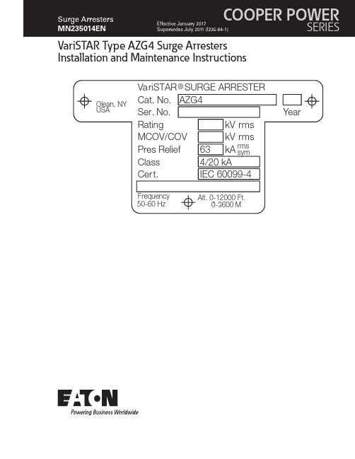
VariSTAR Type AZG4 Surge Arresters Installation and Maintenance InstructionsDISCLAIMER OF WARRANTIES AND LIMITATION OF LIABILITYThe information, recommendations, descriptions and safety notations in this document are based on Eaton Corporation’s (“Eaton”) experience and judgment and may not cover all contingencies. If further information is required, an Eaton sales office should be consulted. Sale of the product shown in this literature is subject to the terms and conditions outlined in appropriate Eaton selling policies or other contractual agreement between Eaton and the purchaser.THERE ARE NO UNDERSTANDINGS, AGREEMENTS, WARRANTIES, EXPRESSED OR IMPLIED, INCLUDING WARRANTIES OF FITNESS FOR A PARTICULAR PURPOSE OR MERCHANTABILITY, OTHER THAN THOSE SPECIFICALL Y SET OUT IN ANY EXISTING CONTRACT BETWEEN THE PARTIES. ANY SUCH CONTRACT STATES THE ENTIRE OBLIGATION OF EATON. THE CONTENTS OF THIS DOCUMENT SHALL NOT BECOME PART OF OR MODIFY ANY CONTRACT BETWEEN THE PARTIES. In no event will Eaton be responsible to the purchaser or user in contract, in tort (including negligence), strict liability or other-wise for any special, indirect, incidental or consequential damage or loss whatsoever, including but not limited to damage or loss of use of equipment, plant or power system, cost of capital, loss of power, additional expenses in the use of existing power facilities, or claims against the purchaser or user by its customers resulting from the use of the information, recommendations and descriptions contained herein. The information contained in this manual is subject to changewithout notice.iINSTALLATION AND MAINTENANCE INSTRUCTIONS MN235014EN January 2017ContentsDISCLAIMER OF WARRANTIES AND LIMITATION OF LIABILITY . . . . . . . . . . . . . . . . . . . . . . . . . . . . . . . . . . . .I SAFETY INFORMATION . . . . . . . . . . . . . . . . . . . . . . . . . . . . . . . . . . . . . . . . . . . . . . . . . . . . . . . . . . . . . . . . . . . .III Safety instructions (iii)PRODUCT INFORMATION . . . . . . . . . . . . . . . . . . . . . . . . . . . . . . . . . . . . . . . . . . . . . . . . . . . . . . . . . . . . . . . . . . .1 Introduction (1)GENERAL APPLICATION RECOMMENDATIONS . . . . . . . . . . . . . . . . . . . . . . . . . . . . . . . . . . . . . . . . . . . . . . . . .1 IDENTIFICATION . . . . . . . . . . . . . . . . . . . . . . . . . . . . . . . . . . . . . . . . . . . . . . . . . . . . . . . . . . . . . . . . . . . . . . . . . .1 ASSEMBL Y . . . . . . . . . . . . . . . . . . . . . . . . . . . . . . . . . . . . . . . . . . . . . . . . . . . . . . . . . . . . . . . . . . . . . . . . . . . . . . .1 Base or Foundation Mounting (2)Bracket or Structure Mounting (2)Suspension Mounting (2)ELECTRICAL CONNECTIONS . . . . . . . . . . . . . . . . . . . . . . . . . . . . . . . . . . . . . . . . . . . . . . . . . . . . . . . . . . . . . . . .2 MAINTENANCE . . . . . . . . . . . . . . . . . . . . . . . . . . . . . . . . . . . . . . . . . . . . . . . . . . . . . . . . . . . . . . . . . . . . . . . . . . . . . . . . . . . . . . .3ii INSTALLATION AND MAINTENANCE INSTRUCTIONS MN235014EN January 2017iiiINSTALLATION AND MAINTENANCE INSTRUCTIONS MN235014EN January 2017Eaton’s Cooper Power series products meet or exceed all applicable industry standards relating to product safety. We actively promote safe practices in the use and maintenance of our products through our service literature, instructional training programs, and the continuous efforts of all Eaton employees involved in product design, manufacture, marketing and service.We strongly urge that you always follow all locally approved safety procedures and safety instructions when working around high-voltage lines and equipment and support our “Safety For Life” mission.1VariSTAR Type AZG4 Surge Arresters Installation and Maintenance InstructionsINSTALLATION AND MAINTENANCE INSTRUCTIONSMN235014EN January 2017Arrester is designed to be operated in accordance with safe operating procedures . These instructions are not intended to supersede or replace proper safety and operating procedures . Read all instructions before installing the arrester .Surge arresters should be installed and serviced only by personnel familiar with good safety practice and the handling of high voltage electrical equipmentProduct informationIntroductionEaton’s Cooper Power series VariSTAR™ AZG4 Class 4, 20 kA Surge Arresters incorporate the latest in metal oxidevaristor (MOV) technology. These arresters are totally gapless and are constructed of a single series column of 76 mm diameter MOV disks. The arrester is designed and tested exclusively to the requirements of the international standard IEC 60099-4 and is available in ratings for the overvoltage protection of high voltage systems through 400 kV .Read this manual firstRead and understand the contents of this manual and follow all locally approved procedures and safety practices before installing or operating this equipment.Additional InformationThese instructions cannot cover all details or variations in the equipment, procedures, or process described nor provide directions for meeting every possible contingency during installation, operation, or maintenance. When additional information is desired to satisfy a problem not covered sufficiently for the user’s purpose, please contact your Eaton representative.Initial inspectionThe factory takes special precautions to ship the arresters in well-designed containers that reduce the possibility of damage, which may occur during transit. Carefully inspect each arrester for physical damage. In case of improperhandling or shipping damage, immediately file a claim with thecarrier and promptly notify Eaton or your local representative.Do not install arresters that have evidence of external damage .Handling and storageIf the arrester is to be stored for an appreciable time before installation, provide a clean, dry storage area. Locate the arrester so as to minimize the possibility of physical damage.Quality standardsISO 9001 Certified Quality Management SystemGeneral application recommendationsEaton’s Cooper Power series product application engineers are available to make specific application recommendations.IdentificationA nameplate attached to the base casting of each VariSTAR Arrester indicates its catalog number, voltage rating (Ur), continuous operating voltage (Uc), rated frequency, pressure relief rated current, class, reference to the type test standard, altitude range, serial number, and year of manufacture.For multiple unit arresters, a nameplate attached to the top casting of each unit indicates the catalog number and serial number of the complete arrester of which the unit forms a part. The unit nameplate also indicates the total number of units comprising the complete arrester and references the position of this unit in the complete assembly.Figure 1 . Unit Nameplate .Always handle surge arresters carefully . Dropping or jarring an arrester may cause serious damage to the porcelain and/or internal parts and may cause catastrophic failure upon energization .AssemblyVariSTAR Type AZG4 Arresters rated 3- through 120 kV are shipped ready for installation. Assemble multiunit VariSTAR Type AZG4 Arresters in a series stack as indicated on the nameplate attached to the top casting of each unit. A grading ring is supplied for standard arresters rated 172 to 360 kV and some arresters of lower voltage rating having extra leakage housings. Grading ring assembly instructions are shown in Figure 8.Choose a permanent location so that the arresters will be installed as (electrically) close as possible to the equipment being protected. Minimum clearance distances between2VariSTAR Type AZG4 Surge Arresters Installation and Maintenance InstructionsINSTALLATION AND MAINTENANCE INSTRUCTIONS MN235014EN January 2017any line potential surface to an arrester and to any ground plane are listed in Table 1. Figures 2 and 3 show alternate mounting arrangements. See Table 1 and Figure 7 forstandard arrester height and leakage distance information.The values shown in T able 1 are the minimum clearances recommended by Eaton . These minimum clearances may be increased to meet local or system requirements for spacing of energized equipment . Safe operating practicesmust always be followed .Make electrical connections so that no mechanical stress is applied to the arrester .Base or foundation mountingPier footings should extend below the frost line. Elevate the foundation sufficiently above the ground line for personnel safety and to prevent contamination from ground splash, drifting snow, floodwater, or other contaminating conditions. If the top of the foundation is not level, shims will be required for leveling. Layout mounting dimensions for the foundation are shown in Figure 6.The base section (unit #1) shall be bolted to the foundation. Units #2, #3 and #4 (as applicable) shall be bolted in place, one unit at a time, until all arrester units and grading ring (ifsupplied) are assembled.The vent port in the base must be directed away from adjacent equipment to prevent ionized gases from damaging other equipment in the unlikely event of arrester failure .Bracket or structure mountingWhen bolting arresters directly to structures, or mountingbrackets, make the assembly rigid enough to prevent mechanical failure.Suspension mountingArresters rated through 168 kV can be suspension mounted. Either the top or bottom of suspension mounted arresters can be connected to the line as long as the sheds on the porcelain housings are not inverted. For additional information regarding suspension mounting, contact yourEaton factory representatives.T o prevent strains on the arrester when suspensionmounting, suspend it freely . Always make flexible connections to line and earth terminals .Electrical connectionsInstall the arrester as close as possible (electrically) to the apparatus being protected. Line and earth connections must be short and direct. Make the earth connection to a solid, effective and permanent low resistance earth.ote:N Equipment protection will be improved by alwaysinterconnecting the arrester earth connections with the transformer tank and system neutral whenever possible.The standard line terminal (Figure 4) and earth terminal (Figure 5) include connector clamps that accommodate 14-335 mm 2 stranded copper or aluminum conductor. This is equivalent to a maximum conductor diameter of 21 mm or 500 mcm.The line and earth terminals allow the connector clamp to be positioned for vertical or horizontal conductor takeoff; in addition, they accommodate industry standard two- or four-hole connectors.Figure 2 . Three-phase triangular mounting .ote:N Refer to Table 1, page 7, for Dimension C.Figure 3 . Three-phase in-line mounting .ote:N Refer to Table 1, page 7, for Dimensions B and C.3VariSTAR Type AZG4 Surge Arresters Installation and Maintenance InstructionsINSTALLATION AND MAINTENANCE INSTRUCTIONS MN235014EN January 2017Figure 4 . Line terminal cap .ote:N Line and earth terminals (suitable for copper oraluminum conductors up to 335 mm 2 (up to amaximum diameter of 20 mm)).Figure 5 . Earth terminal .ote:N Line and earth terminals (suitable for copper oraluminum conductors up to 335 mm 2 (up to a maximum diameter of 20 mm)).MaintenanceBefore working on arresters, disconnect all line leads . Consider any part of an arrester dangerous whenconnected to the line, including a base not solidly earthed .Figure 6 . Base mounting details .* To develop rated cantilever strength use 254 mm bolt circle mounting diameter and 12 mm hardened bolts and flat washers.VariSTAR Type AZG4 Arresters require no specialmaintenance under normal conditions. If the arrester is installed in an area of severe contamination, keep the arrester housing clean by washing periodically. Keep line and earth connections tight.Arresters can be washed while energized provided standard live washing procedures are followed .4VariSTAR Type AZG4 Surge Arresters Installation and Maintenance InstructionsINSTALLATION AND MAINTENANCE INSTRUCTIONS MN235014EN January 2017Figure 7 . Dimensions of VariSTAR T ype AZG4 Surge Arrester .ote:N Refer to Table 1, page 7, for Dimension A.Figure 8 . Grading ring assembly .ote:N Arresters with extra leakage housings may require grading rings in different voltage ratings.5VariSTAR Type AZG4 Surge Arresters Installation and Maintenance InstructionsINSTALLATION AND MAINTENANCE INSTRUCTIONS MN235014EN January 2017T able 1 . Catalog Numbers and Dimensional Information for Standard Arresters . (Contact Eaton Representative forote:N 1. Position #5 designates nameplate options: 0=English 1=Spanish 2=Portuguese2. All arresters are available in grey (standard) or brown porcelain glaze. For brown glaze, substitute “B” for “G” in the eighth position of the catalog number.3. Digits 6 and 7 housing designation may be modified for arresters requiring leakage distance other than the standard arresters shown. Extended leakage may require additional clearances for phase-to-phase and phase-to-earth. Contact your sales representative for this information.4. Cantilever strength for ratings 3-48 kV=10,200 NM and for ratings 54-360 kV=13,550 NM. Maximum working load should not exceed 40% of this value.5. Refer to Figure 7 for Dimension A.6VariSTAR Type AZG4 Surge Arresters Installation and Maintenance InstructionsINSTALLATION AND MAINTENANCE INSTRUCTIONS MN235014EN January 2017This page is intentionally left blank.7VariSTAR Type AZG4 Surge Arresters Installation and Maintenance InstructionsINSTALLATION AND MAINTENANCE INSTRUCTIONS MN235014EN January 2017This page is intentionally left blank.Eaton1000 Eaton Boulevard Cleveland, OH 44122United StatesEaton’s Power Systems Division 2300 Badger Drive Waukesha, WI 53188United States/cooperpowerseries© 2017 EatonAll Rights ReservedPrinted in USAPublication No. MN235014EN/Rev 0117 January 2017Eaton is a registered trademark.All trademarks are propertyof their respective owners.For Eaton’s Cooper Power series productinformationcall 1-877-277-4636 or visit:/cooperpowerseries.。
椰子格四边形修改版(C315X)安装手册说明书
Your safety and the safety of others is very important.§▪In order to help you make informed decisions about safety, we have provided installation instructions and other information.§▪These instructions alert you to potential injury hazards.§▪Please do a job safety analysis before each task to identify potential hazards for your situation and remove/protect against them.§▪You must use your own good judgment.FORWARD:Thank you for purchasing a Fab Fours Roof Rack. As stated in our sales literature, and on the box this rack and manual were packaged in, this product requires drilling into the vehicles roof. As you are aware, the issues from a improper installation can be amplified by the fact if is on the surface that keeps rain out of the vehicle – TAKE SPECIAL CARE – READ ALL GUIDELINES FIRST – READ ALL TROUBLESHOOTING FIRST.This is a measure 5 times drill once scenario, take your time.Fab Fours has zero liability to any damage incurred from the installation and or use of this rack. Not all vehicle roofs are created equal, and there is a large amount ofjudgment involved in deciding to install the rack and where it goes.GUIDELINESYour vehicle is unique and your installation will be as well. Therefore this is not a manual, but guidelines for a successful installation. To keep the nomenclature consistant the parts of the roof rack will be referenced as follows:INSERT IMAGE OF EXPLODED RACK WITH CALLOUTS OF PARTS – SEE GREG SKETCH.•Start by holding one “RACK SIDE” up above your vehicle. Be on a ladder or platform that gives you good visibility of theroof. At this point you are making the first decision aboutwhere the “FEET” will land on the roof. Each set of 4 holes onthe “RACK SIDE” represents the area that a “CROSSBAR”will be. “CROSSBARS” can be mounted with the “MOUNTFLANGE” facing forwards or backwards (if unclear, or firstrack consider a “dry” assembly of a “CROSSBAR” or two offthe vehicle to familiarize yourself with the way a rack isassembled). Therefore, you are trying to find the bestcompromise of having the overall rack in the position you want front to backwards, but also such that the “FEET” will land on the roof in a decent place front to back on the truck.•****WHAT IS A DECENT PLACE FOR A “FOOT”*** o Not too close to a sunroofo Not to close to the edgeo Not “half on” a ridgeo Not in a super flimsy spoto Not on a super curvy spoto Ideally you would like the Front “CROSSBAR” on the rack, and the rear “CROSSBAR” on the rack to bothhave the downward “MOUNT FLANGE” facing the“inside” of the rack. This will prevent you from seeingthe “FEET” when looking at the vehicle.•Now that you know which “CROSSBARS” you intend to have “FEET” mounted to them, and which direction (forwards or backwards to the vehicle) the “MOUNT FLANGES” need to be, you can assemble the Rack off the vehicle! The remaining“CROSSBARS” can face any preference you have.o***IF RUNNING A 50” LIGHTBAR with “studs”, be sure to install prior to tightening rack together. Therack has “holes” instead of slots to discourage theft. •Put 2” spacer on roof.•Put rack on spacers.•Adhere foam to the bottom of the “FEET”.•Visually identify best mount location for the “FEET” left to right in the available holes on the “MOUNT FLANGE”. •Install brackets to where the “FEET” are snug, but can still rotate.•Remove spacers, so that rack is sitting directly on the vehicle. •If happy with location, center punch.o Be sure “FEET” are on flat surface.o Be sure “FEET” still meet criteria for “decent place”. •Remove rack from vehicle.•Loosen all of the “FEET” so they are very “free” moving. •Drill pilot hole.o Use precise listed bits: 1/8”, ¼” 17/32” (if unavailable, a 9/16” bit can be used – take extra care as you are thenalready “oversize” for the crush nuts).•Vacuum away shavings.•Carefully crush nuts. There are 2 primary goals here: 1. Keep the nut flat to the surface at all times. 2. Do not over crush,when it “stops” it is done.•Put rack on vehicle.•Tighten feet to roof. These 8 bolts are the most important in the entire installation. They should spin ALL THE WAYDOWN BY HAND! Make sure they are not getting pressure from the “FEET” or the rack, or anything else. These stainless XXX bolts should have the rubber washer followed by astainless washer. Tighten until the rubber washer is squished to just outside of the washer and the bolt is snug.•Tighten feet to rack.TROUBLE SHOOTING:1.One o r m ore o f t he “CROSSBARS” i s t ouching t he v ehicle i n t he m iddle.a.You c an R emove t hat b ar p ermanentlyb.You c an s pace t hat b ar u p f rom t he “RACK S IDE” w ithwashers.2.One o r b oth e nds o f t he r ack a re m oving t he f limsy r oof t oo m uch.a.You c an p urchase a s m any a dditional “FEET” a s d esired t ospread t he l oad. T hese c an b e i nstalled w ith t he r ack i nplace.3.My S unroof h its a “CROSSBAR”.a.Remove t hat “CROSSBAR” p ermanently.4.When I d rilled m y p ilot h ole, t he b it t hen e ncountered a nother l ayera.Drill t hrough t hat l ayer a s w ell w ith a ll b it s izes.b.If y ou a re u nfortunate a nd l anded o n a s econd l ayer t hat i ssloping o r o n a a ngle (not p arallel t o t he r oof), t hen y ou h aveyour w ork c ut o ut f or y ou. T AKE Y OUR T IME. Y ou s till h aveto d rill t he s econd l ayer w ith a ll s izes o f b its. T he c hallenge i sthat t he b it c an t ry t o “walk” d own t he s econd l ayer t hat w illthen e longate y our r oof h ole. Y ou m ust f ight t hat k eep t hebit c entered t o t ry a nd p rotect t he r ound h ole i n t he r oof. 5.When d rilling I d amaged _____________________ (Insert t hing y oudamaged).a.We c an u nfortunately b e o f n o a ssistance, a nd h old n oliability. W e d o n ot e ven k now w hat v ehicle y ou o wn, o ranything a bout i t. T his i s a u niversal m ount, a nd c hoosing“FEET” l ocation i s a b est j udgment c all. I f y ou r eally h it amess, c onsider h aving t hat l ocation r epaired a nd s hifting t herack t o d rill e lsewhere.Contact InformationFab Fours Inc. Phone (866)-385-19051312 Camp Creek Rd Fax (866)-574-1424Lancaster, SC 29720 *************************More than expected… Better than expected.。
光伏发电系统安装调试及运维维护手册两篇

光伏发电系统安装调试及运维维护手册两篇篇一:光伏发电系统安装调试用户手册阅读说明尊敬的客户,欢迎您使用我公司的光伏发电产品。
我们由衷的希望本产品能满足您的需求。
本手册是我公司为用户提供的安装使用说明。
适用功率5-100kW用户须知●在光伏发电系统安装、操作和维护之前请务必仔细阅读本手册,本手册涵盖该产品使用的各项重要信息及数据,用户必须严格遵守其规定,方可保证该产品的正常运行;●针对任何不按照本手册要求安装和操作机器的行为后果,我司不负任何责任。
符号说明在手册中出现以下符号,是在提示用户需知的重要信息。
警告我公司真诚接受任何针对资料内容上的错误或遗漏而提出的批评指正。
针对任何此资料中未提到的信息,有必要添加或纠正的内容,请联系我公司。
我公司保留在没有通知任何人或组织的情况下对文件信息做更正的权利。
如果用户希望在资料中添加一些使用信息,请联系我司客户服务部或当地的供销商/代理商。
此说明书的解释权归我司。
安全须知不当的操作或没有按照安全指示要求操作设备可能对用户的安全产生危险,并造成重大的硬件损坏,甚至财产损失或人身伤害。
请在操作设备前仔细阅读本手册,并严格遵守下列所有的安全指示。
不要随意打开逆变电源,即使逆变电源的开关已经断开,仍然有可以致命的电压存在。
小小表示可能引起轻微或中等程度损坏的事项。
小小此符号标识表示使系统良好工作所需的重要注意事项。
操作前请断开逆变电源与电网之间的连接;不要触摸与电网、光伏输入回路相连接的端子或导体,任何逆变电源内部与电网之间相连的触点均可能造成燃烧或电击致命。
逆变电源可能由于内部元件的静放电而导致不可恢复的损坏,当操作该设备时,请严格遵守静电防护规范。
电击和火灾可能造成漏电危险,在光伏和电网接入之前请确保逆变电源已经安全接地。
小小任何针对此设备的操作必须由相关的电气专业人员来进行;设备需要维护,请联系本公司专业人员;注意所有安全指示和安装文件中列出的安全注意事项。
1 安装光伏系统的安装主要分为光伏支架、组件的安装,配套电缆的铺设,汇流箱及交直流柜的安装,逆变器的安装几大部分。
潍柴动力赛门铁克防病毒软手册

赛门铁克防病毒软件客户端安装手册潍柴动力扬州柴油机有限责任公司二〇一四年三月目录1卸载所有其他杀毒软件 (2)2 赛门铁克防病毒软件安装程序选择 (3)3 判断电脑内存大小 (4)4 低配置电脑杀毒软件安装步骤 (7)5 中、高配置电脑杀毒软件安装步骤 (12)1卸载所有其他杀毒软件因为2种杀毒软件不能并存(否则会导致死机、蓝屏的故障),因此安装赛门铁克防病毒软件之前必须先卸载其它杀毒软件,如360杀毒、360安全卫士、金山毒霸、金山卫士、MCAFEE、瑞星等。
通过在“开始---程序--控制面板—添加或删除程序”将其它杀毒软件卸载。
2赛门铁克防病毒软件安装程序选择赛门铁克防病毒软件可以根据电脑配置及安全控制需求制定不同的策略,低配置的电脑仅安装基本的防护功能,确保电脑使用性能不受影响,中、高配置的电脑则安装所有防护功能,提供最高防护安全,每台客户端都可以通过服务器端得到及时防护更新。
低配置的电脑:内存1G及以下电脑或设备编号为589-846以前的电脑(如设备编号为589-845)。
中、高配置的电脑:内存1G以上电脑或设备编号为589-846及以后的电脑(如设备编号为589-847)。
3判断电脑内存大小右键点“我的电脑”,选择“属性”出现以下界面则表示该电脑内存为512M,应该安装低配的赛门铁克杀毒软件。
出现以下界面则表示该电脑为2.00GB的内存,即该电脑内存为2G,应该安装装标配的赛门铁克杀毒软件。
4低配置电脑杀毒软件安装步骤点“开始”——“运行”输入\\10.30.37.106, 点“确定”打开“cdr”文件夹,找到“symantec”文件夹打开“symantec”文件夹双击“赛门铁克低配安装程序--低配电脑(内存等于及小于1G).exe”点“运行”,程序正在安装程序安装完成,点“取消”,重启电脑重启电脑后需等待杀毒软件更新病毒库(自动更新,约30分钟),更新完成后在屏幕右下角出现以下界面双击,出现以下界面,表示杀毒软件安装成功。
工业自动化设备安装调试及维护手册

工业自动化设备安装调试及维护手册第一章工业自动化设备安装准备 (3)1.1 设备选型与采购 (3)1.1.1 确定设备需求 (3)1.1.2 调研设备市场 (3)1.1.3 拟定采购方案 (3)1.1.4 招标与评审 (3)1.2 安装现场环境要求 (3)1.2.1 场地要求 (3)1.2.2 设备基础 (4)1.2.3 供电与供水 (4)1.3 安装工具与材料准备 (4)1.3.1 安装工具 (4)1.3.2 安装材料 (4)1.3.3 安全防护用品 (4)1.3.4 辅助设备 (4)第二章设备安装流程 (4)2.1 设备搬运与定位 (4)2.1.1 搬运前准备 (4)2.1.2 设备搬运 (5)2.1.3 设备定位 (5)2.2 设备安装与固定 (5)2.2.1 安装前准备 (5)2.2.2 设备安装 (5)2.2.3 固定检查 (5)2.3 电气连接与调试 (5)2.3.1 电气连接 (5)2.3.2 电气调试 (6)2.3.3 故障处理 (6)第三章设备调试 (6)3.1 调试前的准备工作 (6)3.2 设备功能测试 (6)3.3 设备功能优化 (7)第四章设备运行监控 (7)4.1 运行状态监测 (7)4.2 异常处理与故障诊断 (8)4.3 运行数据记录与分析 (8)第五章定期维护与保养 (8)5.1 维护保养计划 (8)5.2 设备清洁与润滑 (9)5.3 零部件更换与维修 (9)第六章设备故障处理 (9)6.1 故障分类与原因分析 (9)6.1.1 故障分类 (9)6.1.2 原因分析 (10)6.2 常见故障处理方法 (10)6.2.1 硬件故障处理 (10)6.2.2 软件故障处理 (10)6.2.3 电气故障处理 (10)6.2.4 系统故障处理 (10)6.3 故障预防与改进 (10)6.3.1 故障预防 (10)6.3.2 故障改进 (11)第七章安全操作与防护 (11)7.1 操作规程与培训 (11)7.1.1 制定操作规程 (11)7.1.2 操作人员培训 (11)7.1.3 操作人员职责 (11)7.2 安全防护措施 (11)7.2.1 设备防护 (11)7.2.2 环境防护 (11)7.2.3 电气安全 (11)7.2.4 个人防护 (12)7.3 应急处理与预防 (12)7.3.1 应急处理 (12)7.3.2 预防 (12)第八章节能与环保 (12)8.1 节能措施 (12)8.1.1 设备选型与优化 (12)8.1.2 设备运行与管理 (12)8.1.3 能源回收与利用 (13)8.2 环保要求与措施 (13)8.2.1 设备选型与环保要求 (13)8.2.2 设备运行与环保措施 (13)8.2.3 环保型技术应用 (13)8.3 节能与环保技术发展 (13)第九章设备升级与改造 (14)9.1 设备升级需求分析 (14)9.1.1 需求背景 (14)9.1.2 需求分析内容 (14)9.2 升级方案制定与实施 (14)9.2.1 升级方案制定 (14)9.2.2 升级方案实施 (15)9.3 改造效果评价与优化 (15)9.3.1 改造效果评价 (15)9.3.2 改造优化 (15)第十章技术支持与服务 (15)10.1 技术支持体系 (15)10.1.1 技术支持概述 (15)10.1.2 技术支持组织结构 (16)10.2 用户培训与服务 (16)10.2.1 用户培训 (16)10.2.2 用户服务 (16)10.3 技术创新与售后服务 (16)10.3.1 技术创新 (16)10.3.2 售后服务 (16)第一章工业自动化设备安装准备1.1 设备选型与采购工业自动化设备的选型与采购是安装准备阶段的关键环节。
北京煜帮终端维护手册

文档编号:版本号:2010-8-4北京煜帮终端维护手册编制________李庆鑫________审核______________________批准______________________北京煜邦电力技术有限公司2010年08月4日第一部分EDAD2001系列采集器 (4)一、EDAD2001系列采集器介绍 (4)1、基本说明 (4)1.1 ARM版采集器和老版采集器端口的区别 (4)1.2 ARM版采集器单口多规约的设置 (4)2、采集器常用的操作说明 (5)2.1 Linux版采集器操作说明 (5)2.2 DOS版操作说明 (13)2.3 脱硫采集器操作说明........................................ 错误!未定义书签。
3、采集器(DOS版本)文件组成及作用 (15)3.1 可执行程序(C:\EDAD、D:\EDAD) (15)3.2 批处理程序(C:\EDAD、D:\EDAD) (16)3.3 资源文件(C:\EDAD、D:\EDAD) (16)3.4 配置文件(C:\EDAD、D:\EDAD) (16)3.5 数据文件(C:DATA、D:\DATA) (18)4、采集器(Linux版本)文件组成及作用 (18)4.1 /edad目录结构 (19)4.2 /data0及/data1目录结构 (22)5.A采集器的文件组成及作用 (22)二、采集器调试常见问题 (24)1现场调试工作流程 (25)2调试常见问题 (25)2.1 网络通信的调试 (25)2.2 拨号调试注意事项 (27)2.3 召测量的配置方法 (29)2.4 GB645规约电能表的调试 (32)2.5 GPRS通信的调试(来自硬件部提供文档) (34)2.6 采集器网口不够时如何扩充网络功能 (38)2.7 程序升级注意事项 (40)2.8 取得采集器界面密码的方法 (41)2.9 配置文件RATE.INI (41)2.10 关于102规约的调试事项 (42)2.11 关于对时功能的说明 (44)2.12 四象限无功的采集以及负荷曲线的读取 (45)2.13 日冻结与月冻结 (45)2.14 采集器双备份 (46)3、现场调试FAQ(专用) (48)3.1 青海项目调试注意事项 (48)3.2 河北变电站项目调试事项 (50)3.3 河北地电项目的标准配置 (51)3.4 各地不同的特色,比如规约 (52)附件1调制解调器的指示灯及常用指令简介 (52)1.1 MODEM工作状态查看方法: (52)1.2MODEM常用指令 (52)附件2 各地项目文件模板 (54)2.1 河北地电项目CALLBUF.INI文件模板 (54)附件3 FTPHOST远程维护软件使用说明 (65)一、简介 (65)二、准备工作 (65)三、进行远程维护操作 (68)附件4 RemoteConfig3维护软件使用说明 (74)附件 5 采集器资源配置表........................................................ 错误!未定义书签。