蓝马转换器f使用说明书
--F620简易中文使用手册
F620简易中文使用手册1。
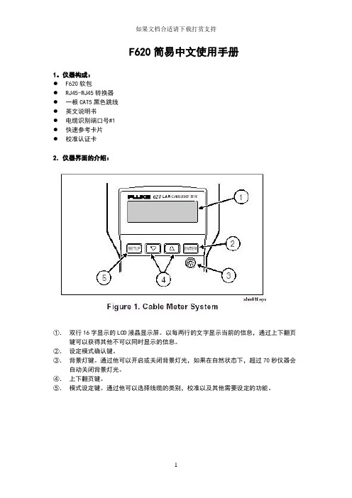
仪器构成:●F620软包●RJ45-RJ45转换器●一根CAT5黑色跳线●英文说明书●电缆识别端口号#1●快速参考卡片●校准认证卡2.仪器界面的介绍:①.双行16字显示的LCD液晶显示屏。
以每两行的文字显示当前的信息,通过上下翻页键可以获得其他不可以同时显示的信息。
②.设定模式确认键。
③.背景灯键。
通过他可以开启或关闭背景灯光,如果在自然状态下,超过70秒仪器会自动关闭背景灯光。
④.上下翻页键。
⑤.模式设定键。
通过他可以选择线缆的类别,校准以及其他需要设定的功能。
①OFF:关闭仪器。
②TEST:自动测试。
提供通过或失败的结果报告,指出有问题线缆的地点。
③LENGTH:长度测试。
以英尺或米为单位提供线缆的线对长度和总体长度。
④WIRE MAP:接线图测试。
指出开路,短路,串绕等故障现象。
①左:标准的DB9针接口,连接IBM屏蔽双绞线或者数据电缆。
②中间:标准的8针RJ45接口,连接屏蔽或非屏蔽双绞线。
③右:标准的BNC铜轴电缆接口,提供对铜轴电缆的物理测试。
3.其他信息①声音信号:测试仪器通过不同的声音信号来通知不同的测试结果。
一声短的声音信号表示当前测试结果是在没有连接远端识别器的前提下通过的;两声短而急促的声音信号表示当前结果是在连接有远端识别器的情况下通过的;三声音频信号则表示当前测试结果失败;一声长的声音信号表示当前未曾检测到被测设备;一声持续的变化着的音频信号表示当前连接在一个活动的物理设备上有可能会突然中断;具体设置是否使用音频信号需在“SET UP”档里面设置。
②低电量警示当显示屏幕上出现“LOW BATTERY”的时候,提示你当前电池电量告警,但还可以使用8个小时左右;但是当反复在屏幕上出现“REPLACE BATTERY”的时候,代表当前电池需要立即更换。
③节约电池电量当持续超过10分钟对仪器未有任何设置和改动时,仪器会自动切断电源强制关机。
在这种情况下如果还要继续测试的话,需要先把旋钮转到OFF键,然后过5秒钟之后重新开启,进行测试。
氧化气燃料转换器安装说明书

Model 1100MN 1100MP GasNatural Propane Altitude (Ft.)*0-4,500 feetInput Maximum (Btu/h)30,00030,000Input Minimum (Btu/h)16,00016,000Manifold Pressure (in w.c.) 3.5”9”Minimum Supply Pressure (in w.c.)5”11”Maximum Supply Pressure (in w.c.)10”14”Main Burner Injector Marking 36 DMS 51 DMS PSE Pilot Injector Marking BL22N BL14LP Min. Rate By-Pass Screw1851254009100-02©2022, Miles Industries Ltd.This appliance is certified for use from 0–4500 feet. For altitudes above 4500 feet, see local codes.Kit Contents1 Pilot injector 1 Main burner injector 1 Set of conversion labels 1 Minimum rate by-pass screwTools Required• Wrenches, to disconnect gas line • Phillips (+) screwdriver• Small (jewelers size) flat blade screwdriver, to set pressure• Small flat blade screwdriver, to release pressure tap on valve• Needle nose pliers, to remove bypass screw • Allen key, 5/32”, to change bypass screw • Wrench, 7/16”, to remove pilot hood and injector • Socket wrench, 7/16”, with extension to change main burner injector• Manometer, to set pressureSpeci fi cations1100MNGK / 1100MPGK Gas Conversion KitFor Valor 1100M fireplaces ONLYINSTALLATION MANUALH5 SeriesGeneral Notes Regarding ConversionThe conversion may be done before or after theappliance is installed into the cavity. However, the gas must be connected to set the manifold pressure.Prepare the applianceSee your Installation Manual for help with these steps.1. If the fireplace is already installed, remove theaccess side doors, the front trim, the window, fuelbed and liner panels. Be careful with the fuel bed and liner panels as they are fragile.2. Locate shut off valve and isolate. Disconnect the fuelline from the valve after it is shut off.3. Remove the cover panel surrounding the burner (4screws).4.5.Remove the burner by undoing 2 screws and pullingthe burner gently forward, then up.6. Remove the burner module by undoing 12 screws(including those holding down the air deflector).Remove the air deflector, and then the module bylifting forward and then up. Be careful not to hookthe aeration block above, or the control valvebelow, as you pull the burner module up.Disconnect connections to the receiver to allowthe burner module to come free of the fireplace.Replace the burner injector1. Using a 7/16” socket wrench with extension,unscrew the old burner injector within the aerationblock.2.Dispose of old burner injector.3.Replace with new burner injector (see Specificationstable on page 1). Tighten in place with socketwrench.4. Unscrew and flip the air shutter stopper over.Position required for each fuel is illustrated below.Reattach using original screws.Aeration blockInjectorNaturalgasPropane2Replace the minimum rate by-pass screw1. Turn module assembly upside down, unlock andremove pipe assembly.2. Remove two screws retaining the valve to mountingbracket, being careful not to disturb other connections.3. Locate and remove the by-pass screw using the 5/32”Allen key from the valve and discard. The by-pass screw has a rubber O-ring and may need to be pulled out using pliers after unscrewing.4. Insert the replacement minimum rate by-pass screwand hand tighten using the 5/32” Allen key. Refer to the Specifications table on page 1 for proper by-pass screw. Note that the number is stamped on the barrel of the screw. 5. Replace the control valve onto its mounting bracket,and re-attach. Reconnect any connections removedfrom the control valve.Underside of control valve• Minimum rate By-pass screw locationConvert the pilot injector1. Remove the pilot hood using a 7/16” wrench.2. Remove the old pilot injector with needle nosepliers, or turn the pilot over and the old pilot injector will fall out. Discard the old pilot injector.3. Replace with the appropriate pilot injector—seeSpecifications table on page 1. Drop in the new injector, flared side down.4. Refit the pilot head by threading it back into itsfitting, and tighten with a 7/16” wrench until thehood points directly at the thermocouple.3Re-assemble moduleTo reinstall, reverse the previous procedures.1. Position and locate module in the firebox insertingthe valve first. Be careful not to trap cables between firebox frame and module.2. Reconnect any connections previously undone tothe receiver.3. Secure module and air deflector to firebox withpreviously used screws (12).4. Reconnect gas inlet to valve using sealant andtightening pipe connection. Open shut off valve and inspect 5. Test for leaks by applying a liquid detergent or soap solution to inlet connection joint. Bubbles forming indicate a gas leak.6. Reinstall burner to burner module. Gently insertburner tube into aeration block, and drop onto brackets on burner module. Screw in 2 screws.7. Check that the aeration lever moves properly. Theair shutter should move with the lever (cutout shown below for clarity of the lever’s location).Set the manifold pressure1. Fit a manometer to the manifold pressure test tapon the valve—see figure below.2. Light the appliance and turn the control to full input.3. Adjust the pressure adjustment screw using a smalljeweller’s size flat blade screwdriver—as shown below—while the appliance is running at full input to produce manifold pressure, as perSpecifications table on page 1.4. Turn off the appliance, remove the manometer andtighten the test tapping screw. 5. Check all connections for leaks.Front Face of Control ValvePry off Plastic Cap4Continue re-assembly1. Resintall the rear baffle (6 screws).2. Reinstall the burner cover (4 screws).Reinstall the liners and fuel bedTo reinstall the liners and fuel bed to the installation of the fireplace, see the installation instructions supplied with the appliance.Perform aeration adjustmentOnce the fuel bed is in place, securely replace the front window and adjust the aeration lever as necessary. Seethe Installation Manual for details.Fit the speci fi cations label1. Complete the required details of label “Thisappliance was converted on... by...” position along with the label “This control has been converted...”.2. Fit the labels to the bottom floor of the appliance asclose as possible to the data card and the valve as indicated below.3.Replace any remaining doors, covers, and trim.Designed and Manufactured by / for Miles Industries Ltd.190 – 2255 Dollarton Highway, North Vancouver, B.C., CANADA V7H 3B1Tel. 604-984-3496 Fax 604-984-0246www.valor fi Because our policy is one of constant development and improvement, details may vary slightly from those given in this publication.5。
福伊特电液转换器的使用说明书

VOITH电液转换器使用说明书型号:DSG-BXX113目录1.技术数据 (1)2.安全指示 (3)2.1 提示和标志的定义2.2 正确使用2.3 重要提示2.4 担保3.功能描述 (6)3.1 设计3.2 操作特点4.包装、储存、运输…………………………………………75.安装…………………………………………………………85.1 组装5.2 液压连接5.3 电器连接6. 试运行 (10)6.1 运行检测6.2 参数设定7.操作 (11)7.1 用手动旋钮操作7.2 用设定信号操作7.3 故障检修和排除8. 维护和检修…………………………………………………9. 停机…………………………………………………………1、技术数据:周围环境:储存温度-40 (90)工作环境温度-20 (85)保护IP65 to EN 60529适合于在工业空间内部安装电气数据:电压:24 VCD ±15%电流:大约0.7A(对DSG-B05…DSG-B10型)大约1A(对DSG-B30型)最大3A 时间t ‹1 Sec输入设置:0/4…20mA输入阻抗大约25欧姆,具有抑制电路。
液压参数:最小进口油压P in min: 1.5bar+最大输出P A max(对B05…B10型)5bar+最大输出油压P A max(对B30型)最大进口油压P in max :见表压力流体:不易燃烧的原油或压力油油粘度:根据DIN51519,ISO VG32…ISO VG48油温:+10℃ (70)油纯度:根据NAS1638为7级根据ISO4406为-/16/13级泄漏量:当进口油压P in=10bar 时≤3 l/min (对DSG-B05…DSG-B10 ) 当进口油压P in=40bar 时≤5 l/min(对DSG-B30)P A最小值调整范围处决于P A最大值的设定值.。
上面表中所示P A最小值的调整范围参考P A max的最小调整值机械参数:安装尺寸:见第十章液压连接:见第十章安装位置:见第十章密封材料:FPM重量:大约12kg2.安全指示:2.1提示和标记的定义:危险:这标志标示对人的生命和健康带会带来危险,如不遵照此提示,将会对健康发生危害,甚至发生更加严重的损害。
电磁流量计转换器使用说明书

3.2.9电气隔离
模拟输入与模拟输出间绝缘电压不低于500V;
模拟输入与报警电源间绝缘电压不低于500V;
模拟输入与交流电源间绝缘电压不低于500V;
模拟输出与交流电源间绝缘电压不低于500V;
模拟输出与大地之间绝缘电压不低于500V;
脉冲输出与交流电源间绝缘电压不低于500V;
脉冲输出与大地间绝缘电压不低于500V;
POUT为集电极开路输出,用户接线时可参照如下电路:
4.5.3.1数字量电平输出接法
图4.5(a)数字量电平输出接法
4.5.3.2数字量输出接光电耦合器(如PLC等)
图4.5(b)数字量输出接光电耦合器
一般,用户光耦需10mA左右电流,因此,E/R=10mA左右。E=5~24V。
4.5.3.3数字量输出接继电器
TRX-:
通讯输入
LN+:
220V电源输入
LN-:
220V电源输入
4.4
4.4.1信号线处理
图4.4.1信号线处理
信号线标示如下:
双股线:红色12芯线
黑色12芯线
黑色双股蔽线:红色10芯线接“信号1”
黑色13芯线接“信号2”
屏蔽线接“信号地”
4.4.2流量信号线
转换器与传感器配套使用时,对被测流体电导率大于50μS/cm的情况,流量信号传输电缆可以使用型号为RVVPB2*0.12*280 mm2的聚氯乙烯护套金属网屏蔽信号电缆。使用长度应不大于100m。信号线与传感器配套出厂。信号线的处理可按图4.4.1进行.本转换器提供有等电位激励屏蔽信号输出电压,以降低电缆传输的分布电容对流量信号测量的影响。当被测电导率小于 或长距离传输时,可使用具有等电位屏蔽的双芯双重屏蔽信号电缆。例如STT3200专用电缆或BTS型三重屏蔽信号电缆。
M-MAX 频率转换器系列产品信息说明书

MMX34AA012F0-0MMX34AA4D3F0-0MMX12AA3D7F0-0MMX12AA9D6F0-0MMX34AA1D3F0-0 MMX12AA1D7F0-0MMX12AA2D4F0-0MMX12AA4D8F0-0MMX34AA1D9F0-0MMX34AA2D4F0-0Operating comfort redefined Frequency Inverters M-MAXProduct InformationFrequency Inverter M-MAXM-MAX Frequency InverterSystem FeaturesThe M-MAX series frequency inverters allow drives to be adapted easily to customer requirements. With a compact design for assigned motor ratings from 0.25 kW to 5.5 kW, M-MAX can offer maximum flexibility. M-MAX also demonstrates how a high level of functionality can be implemented in a simple and user-friendly design. The small and compact book format design also allows a space saving installation. M-MAX is provided with an integrated RFI filter (EMC) and a flexible interface for solving important machine building requirements, for example, the optimization of production and manufacturing processes. It reliably ensures the required motion sequences of the drive motor and thus contributes to operational safety.M-MAX – the “energy optimizer“M-MAX frequency inverters provide an economical solution for several processes in pumping applications. The integrated PI controller and extensive motor-protective functions ensure a high level of operational reliability and allow significant energy savings in the connected process. The lacquered control boards also allow use in highly humid and aggres-sive environments, such as in a sewage treatment plant. The optional MMX-IP21-FS... accessory enables the degree of protection of the M-MAX to be increased to IP21.M-MAX – the “safe operator“Good climatic conditions as well as safe operation in the event of fire (fume removal) are demanding tasks for frequency controlled ventilation systems in buildings. With its internal protective circuits and the automatic restart option (e.g. after a momentary power failure), as well as automatics ynchronization with the running motor (flying restart circuit), the frequency inverters of the M-MAX series ensure the safe operation of fans in air conditioning and smoke control systems.M-MAX – for “dynamic precision“The compact design of the M-MAX saves valuable mounting space in machine building since the RFI filter and the brake chopper are already integrated. Shielded control and motor cable can also be connected with EMC compliance directly to the frequency inverter. The maximum permissible ambient temperature of +50 °C during operation with continuouscurrent and with full overload withstand capability also meets machine building requirements. The performance of the sensorless vector control ensures also a high speed accuracy; even with load deviations and low motor speeds.MMX-COM-PC – the “in-line communicator“The MMX-COM-PC communication module that can be plugged onto the front provides the following without a mains voltage on the frequency inverter (internal battery):Upload and download of all parameters,• Direct link to a PC via USB interface (parameter • assignment),Copying of parameters for series machines or when • exchanging devices.This communication module considerably increases datas ecurity and reduces the time required for commissioning and maintenance.FeaturesIntegrated RFI filter (EMC: C2 and C3 to/EN61800-3)• Dynamic motor control with sensorless vector control or V/f • control (selectable)Integrated keypad and display unit• Electronic reference value potentiometer • Fixed frequencies • PI controller• Integrated brake unit (with MMX34 in sizes 2 and 3)• 6 digital control inputs (24 V DC)• 1 digital output (transistor, 24 V DC, 50 mA)• 2 analog inputs (0...+10 V DC and 0/4.20 mA)• 1 output analog (0/4...20 mA)• Serial interface (RS485 / Modbus RTU)• 2 relays (1x NO, 1x changeover, 230 V AC, 2 A)• International standards (CE, UL, cUL, c-Tick)• Application examplesSpeed control of asynchronous three-phase motors up to • 5.5 kW (400 V)Pump and fan applications in buildings and industrial areas • with quadratic and linear load characteristics.The high speed accuracy (sensorless) allows a whole range • of possible applications in the textile, paper and printing industry, as well as with finishing machines in the metal industry.The compact design with integrated EMC filter offers• maximum flexibility in machine building and saves valuable mounting space.The twofold startup torque and 1.5 overload torque allows • the implementation of applications with demanding speed and torque requirements.Frequency inverters - simple and straightforwardDisplay unitFunction keysSTARTMotor start via keypad(function must be activated)STOPMotor stop via keypad• Acknowledges the display fault message (Reset)• Activates the Startup Wizard (press for 5 s)• OKActivates the selected parameter • Confirm the set value• Parameter group selection (submenu)• BACK/RESETBack in menu. Exit edit mode and acknowledge error messages (reset).LOC/REMMove between different control levels (keypad – control terminals – fieldbus)UP/DOWNMenu level selection in the display unit (• Y )Change in the parameter groups and • parameter listsIncrease and reduce parameter values • Increase and reduce reference value • (electronic motor potentiometer)Status symbols (D ):READY = Ready to start RUN = Operational STOP = S top, Stop command active ALARM = Alarm message active FAULT = D rive was stopped due to an error message Menu level (Y ):REF = Reference value entry MON = Monitor operating data PAR = Parameters FLT = Fault memory (Fault)Control commands (C ):FWD = Forward run REV = Reverse run I/O = Via control terminals (Input/Output)KEYPAD = Via the keypad BUS = Via fieldbus (interface)Backlit liquid crystal display (LCD)Technical data (extract)*) Rated motor current for normal four-pole internal and surface cooled asynchronous three-phase motors (1500 rpm). Operating dataAccessoriesEaton’s electrical business is a global leader in electrical control, power distribution,uninterruptible power supply and industrial automation products and services.Eaton’s global electrical brands, including Cutler-Hammer ®, MGE Office Protection Systems™, Powerware ®, Holec ®, MEM ®,Santak and Moeller, provide customer-driven PowerChain Management® solutions to serve the power system needs of the industrial,institutional, government, utility, commercial,residential, IT, mission critical and OEM markets 4 *p a t p k a #y .x y c m *Moeller addresses worldwide:/address E-Mail: info @ Internet: w Issued by Moeller GmbH Hein-Moeller-Str. 7-11D-53115 Bonn© 2008 by Moeller GmbH Subject to alterations W8230-7606en ip 01/09Printed in Germany (01/09)Article No.: 121384MMX34AA9D0F0-0MMX34AA5D6F0-0MMX34AA7D6F0-0MMX12AA2D8F0-0MMX34AA012F0-0MMX34AA4D3F0-0MMX12AA3D7F0-0MMX12AA9D6F0-0MMX34AA1D3F0-0 MMX12AA1D7F0-0MMX12AA2D4F0-0MMX12AA4D8F0-0MMX34AA1D9F0-0MMX34AA2D4F0-0。
转换器使用说明书
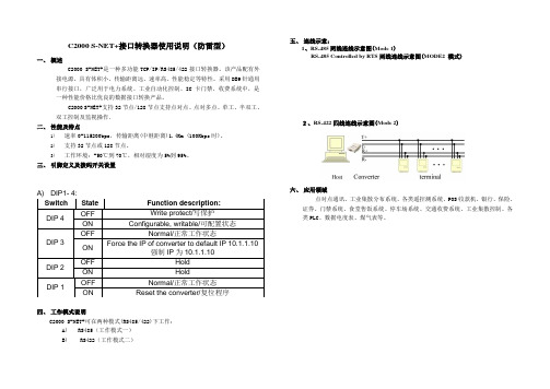
C2000 S-NET+接口转换器使用说明(防雷型)一、概述C2000 S-NET+是一种多功能TCP/IP/RS485/422接口转换器。
该产品配有外接电源。
具有体积小、传输距离远、速率高、性能稳定等特性。
采用DB9针通用串行接口,广泛用于电力系统、工业自动化控制、IC卡门禁、收费系统中,是一种性能价格比优良的数据接口转换产品。
C2000 S-NET+支持32节点/128节点支持点对点、点对多点、单工、半双工、双工控制及监视操作。
二、性能及特点1)速率0-115200bps,传输距离(中继距离)1.4Km (100Kbps时)。
2)支持32节点或128节点。
3)工作环境:-50℃到70℃,相对湿度为5%到95%。
三、引脚定义及拨码开关设置DIP 4 OFF Write protect/写保护ON Configurable, writable/可配置状态DIP 3 OFF Normal/正常工作状态ONForce the IP of converter to default IP 10.1.1.10强制IP为10.1.1.10DIP 2 OFF Hold ON Hold四、工作模式说明C2000 S-NET+可在两种模式(RS485/422)下工作:A)RS485(工作模式一)B) RS422(工作模式二)五、连线示意:1、RS-485两线连线示意图(Mode 1)RS-485 Controlled by RTS两线连线示意图(MODE2模式)2、RS-422四线连线示意图(Mode 2)六、应用领域点对点通讯、工业集散分布系统、各类遥控测系统、POS收款机、银行、保险、证券、门禁系统、食堂售饭系统、停车场系统、交通收费系统、工业集散控制、各类PLC、数据电度表、煤气表等。
Switch State Function description:DIP 1 OFF Normal/正常工作状态ON Reset the converter/复位程序资料精选,适合职场人士使用借鉴参考。
SGT00L-0162 转换器使用说明书
转换器使用说明书SGT00L-0162转换器1本转换器兼容USB 2.0转RS232与RS485,信号输出满足RS485标准,通讯距离大于1200米,通讯带载大于30个,通讯波特率小于或等于19200BPS,产品经过GB/T17626.4电快速瞬变脉冲群干扰度等级III实验要求,GB/T17626.5浪涌(冲击)抗扰度等级III实验要求。
21、采用业界公认的高性能USB接口芯片FT232RL,全部采用进口(英国封装芯片),可靠性高;2、采用ADI公司磁耦合隔离技术,性能强,寿命长;3、波特率范围:300~460800bps;适应市场上99%的场合使用;4、采用顺源IB0505S-1W单路输出稳压有自恢复过载短路保护模块电源,IB S/D系列模块电源,定电压输入1KVAC隔离稳压单输出,输出端有过载和短路保护功能,空载时电压不会升高。
主要用于自动化设备、数控机床、停车场、门禁刷卡等,与计算机控制系统需要通讯的RS232/RS485接口防雷抗干扰电源隔离。
5、前后采用双电感滤波网络,使得电源纹波降低至10mV以下(峰峰值);6、采用性能强、成本高的RS-485接口工业级芯片SN65LBC184(普通都用SN75LBC184民用芯片),此芯片不但自带瞬变电压抑制,而且负载仅为RS-485标准的1/4,换句话说总线上可接128个此设备(也需要是1/4负载的接口);7、使用2个德国EPCOS爱普科斯防雷管B3D090L,让你使用中毫无顾虑。
8、接口电路采用三级防护级联(放电管+TVS+RC滤波),再也不怕恶劣的工控环境了;9、全工业级设计,保证使用全新进口芯片;温度范围:-40℃~85℃。
31.本品基于目前公认比较稳定的英国FTDI公司FT232芯片(非PL2303/CH340可比),提供两个输出接口:RS232/RS485。
2.三个工作指示灯(电源、发送、接收),及时提示工作状态。
3.采用高硬度的铝合金外壳(有效防摔)和配高品质全铜带屏蔽的USB数据线(私人订制)。
电磁流量计转换器说明书要点
电磁流量计转换器使用说明书L- mag系列2007年02月目录1. 产品功能说明 (1)1.1 基本功能 (1)1.2 特殊功能 (1)1.3 正常工作条件 (1)1.4 与传感器连接型式 (2)1.5 安装尺寸图 (2)2. 转换器基本电路 (3)3. 技术性能指标 (4)3.1 执行标准 (4)3.2 基本参数与性能指标 (4)4. 转换器操作 (7)4.1 键盘定义与显示 (7)4.2 转换器剖面图 (9)4.3 转换器接线图 (11)4.4 连接电线电缆特性及连接要求 (13)4.5 数字量输出及计算 (16)4.6 模拟量输出及计算 (18)5. 仪表参数设置 (21)5.1 按键功能 (21)5.2 参数设置功能及键功能操作 (22)6. 掉电时间记录(带掉电功能) (31)6.1功能部件 (31)6.2掉电记时记录的数据格式 (31)6.3查看掉电记录 (32)6.4清除掉电记时记录 (32)7. 小时总量记录(带小时总量记录功能) (32)7.1功能部件 (32)7.2小时总量记录格式 (32)7.3查看小时总量.................................................................................................................. 33 I7.4清除小时总量记录 (33)8.红外手持遥控键盘 (33)9. 报警信息 (34)10. 故障处理............................................................................................................................. 34 10.1 仪表无显示. (34)10.2 励磁报警.......................................................................................................................34 10.3 空管报警....................................................................................................................... 34 10.4 测量的流量不准确. (35)11. L_MAG装箱与贮存........................................................................................................... 35 11.1 L_MAG 装箱................................................................................................................. 35 11.2 运输和贮存. (35)附录一励磁频率选择(参考) (36)附录二拨码开关说明 (38)附录二 L_MAG转换器HART 功能说明........................................................................... 39 IIL_mag电磁流量转换器使用说明书1. 产品功能说明1.1 基本功能■ 低频方波励磁,励磁频率:1/10工频、1/16工频、1/25工频、1/32工频;■ 高频方波励磁,励磁频率:1/2工频(适用于浆液测量);■ 励磁电流可选定为125mA 、187.5mA 、250mA ;■ 无需附加电极的空管测量功能,连续测量,定值报警;■ 流速测量范围:0.1 --- 15米/秒,流速分辨率:0.5毫米/秒;■ 交流高频开关电源,电压适用范围:85V AC --- 250VAC ;■ 直流24V 开关电源,电压适用范围:16VDC --- 36VDC;■ 网络功能:MODBUS (RS-232C 、RS-485)HART 、PROFIBUS-DP (选配);■ 中文、英文显示方式, (可定制其它语言);■ 内部有三个积算器总量,可分别记录:正向总量、反向总量、差值总量。
F2D-Super电影到数字转换器v1.0用户手册说明书
10. Edit Image Orientation (12)11. Change Image EV (Exposure Value) and RGB Color ... 13 12. Convert Film to Digital File ... 13 13. Playback and Edit Converted Image Files ... 14 14. Connect F2D-Super to Computer to Upload Image Files ... 16 15. Upload Image Files to PC and Delete the Uploaded Files ... 16Technical Support ... 17Specifications ... 18Caution ... 19One-Year Limited Warranty (United States Only) ... 19Warranty Exclusions ... 21Other Limitations (22)Thank You for Choosing Wolverine and Quick Start ... Back Cover 1Introduction Thank you for purchasing Wolverine F2D-Super Film to Digital Converter . You can take stacks of film and convert them into digital images to preserve them forever. Wolverine has created a simple-to-use device to convert your film into high mega pixel digital images in seconds. No computer or software is needed. Plug the F2D-Super into an outlet or a USB port; all images are saved to memory or optional SD/SDHC memory card. The F2D-Super can be connected with your Windows PCs or Mac computer system to upload converted and saved digital images through USB ports.Before Using F2D-SuperThis section provides important safety information that you should read before using your F2D-Super.Do not drop or handle too aggressively as it may cause damage to the device.Do not allow the device to come into contact with water or other liquids. In the event that water or other liquids enter the interior,..2immediately turn off the device. Continued use of the device may result in fire or electric shock.Do not handle the device with wet hands. Doing so may cause electric shock and damages to the unit.Do not place the device close to any equipment generating strong electromagnetic fields. Exposure to strong magnetic fields may cause malfunction or data corruption. Do not expose the device to extreme temperatures, humidity or vibrations, which may cause damages to the device.Do not open the outer casing. This unit does not require batteries or contain user serviceable parts.Do not move or disconnect the device from the computer while the device is reading/writing data. This may cause damages to the data and/or the device.Under no circumstances should user try to repair the device. Doing so may cause electric shock and void the warranty.Warranty will be voided if the device is mishandled. Please take care in handling the device. Wolverine Data is not responsible for.......3consequential damages, including loss of data. Always back up all data. For full warranty statement see the end of this manual.Wolverine Data has no obligation to repair, replace or issue refunds without a Return Merchandise Authorization (RMA) number and the original purchase receipt of the defective product.Repairs or replacement service will not be offered to products that were misused, scratched, repaired without authorization, or any other reasons beyond the range of intended use.Replacement product may be either new or refurbished, provided that its functions are at least equal to that of the product being replaced.Wolverine Data is not responsible for any data stored on the returned product, please backup any data prior to ship back the unit.All out of warranty repairs are subjected to repair fee. Please contact your dealer or Wolverine Data for current charges....B power adapter, USB to order extra adapters, inserts, or optional accessories, SD memory card, .. . .86. Set Film Type E nsure the Film Type setting is correct, or you will see X-ray-like image on the viewer. Refer to File Type Table on page 9. The film type setting will remain until changed even when F2D is powered off. 1. At Film Type menu, press OK/Enter key.2. Press Left or Right key to highlight Color Negatives or Slides Positive or B&W Negative then press OK key to select .3. Press Left or Right key to highlight the type of film then press OK .. Film Type - Selects type of film to convert, refer to Film Type Table on page 9. Delete All - Deletes all files in the internal memory or the inserted SD/SDHC card . Convert - C onverts film to digital image . Playback - Reviews all converted images stored in memory . USB MSDC - Communicates with PC or Mac to upload converted images files to a computer . Language - Sets menu in English or Japanese 97. Select Proper Adapter or/and InsertSelect proper Adapter or/and Insert to convert your film, refer to File type tableabove. If 110 Insert or Super 8 Insert is selected, Film Type Color Negative 110126KPK 135Slide Positive Super 8110126KPK 135B&W (black &white)110126KPK 135Format Film Width 16 mm 26 mm 35 mm 8 mm 16 mm 26 mm 35 mm 16 mm 26 mm 35 mm Negative Adapter & 110 Insert Negative Adapter only Negative Adapter & 110 Insert Negative Adapter only Negative Adapter & Super 8 Insert Slide Adapter only Adapter or/and Insert to Use * Popular types in Bold & Italic File Type Table14. Connect F2D-Super to Computer to Upload Image Files15.18Specifications Lens: F/3.48, f=5.12LCD:2.4 inch LTPS LCD DisplayExternal memory: SD/SDHC card Exposure: Auto Color balance: Auto Resolution: 20 MP Data conversion: 24 bits per color channel Convert method: Single passLight source: backlight Power: Powered from USB/5V adapter Interface: USB 2.0Dimension: 103 x 90.5 x 104 mm Weight: 215 gLanguage: English and Japanese 19Caution This device complies with part 15 of the FCC Rules.Changes of modifications not expressly approved by Wolverine Data could void the user 's authority to operate the equipment.One-Year Limited Warranty (United States Only)Wolverine Data manufactures its hardware products from parts and components that are new or equivalent to new in accordance with industry-standard practices. Wolverine Data warrants that the hardware products it manufactures will be free from defects in materials and workmanship. The limited warranty term is one year beginning on the date of invoice, as further described in the following text. Damage due to shipping the product is covered under this limited warranty. Otherwise, this limited warranty does not cover damage due to external causes, including accident, abuse, misuse, problems with electrical power, servicing not authorized by Wolverine Data, usage not in accordance with product instructions, failure to perform required preventive maintenance, and problems caused by use of parts and components not supplied by Wolverine Data.The warranty extends only to the first consumer purchaser, and is not transferable. This limited warranty does not cover any items that are in one or more of the following20categories: software; external devices (except as specifically noted); accessories or parts added to a Wolverine Data system after the system is shipped from Wolverine Data or its resellers; accessories or parts that are not installed in the Wolverine Data factory. During the one-year period, beginning on the invoice date, Wolverine Data will repair or replace products returned to Wolverine Data's facility.To request limited warranty service, you must contact Wolverine Data's Technical Support Services within the limited warranty period. Refer to the section titled TECHNICAL SUPPORT to find the appropriate telephone number for obtaining customer assistance. If limited warranty service is required, Wolverine Data will issue a RMA (Return Material Authorization) Number. You must ship the products back to Wolverine Data in their original or equivalent packaging, prepay shipping charges, and insure the shipment or accept the risk of loss or damage during shipment. Wolverine Data will ship the repaired or replacement products to you freight prepaid if you use an address in the continental United States, where applicable. Shipments to other locations will be made freight collect.To obtain service, you must include: (a) a copy of your receipt or other comparable proof of purchase; (b) a written description of the problem; (c) your address and telephone number; (d) Write the RMA number on the outside shipping packaging. NOTE: Wolverine Data uses new and reconditioned parts made by various manufacturers in performing limited warranty repairs and building replacement products. If WolverineData repairs or replaces a product, its limited warranty term is not extended.21Warranty Exclusions Normal Wear and TearPeriodic maintenance, repair and replacement of parts due to normal wear and tear are excluded from coverage.Abuse and Misuse Defects or damage that result from: (a) improper operation, storage, misuse or abuse, accident or neglect, such as physical damage (cracks, scratches, etc.) to the surface of the product resulting from misuse; (b) contact with liquid, water, rain, extreme humidity or heavy perspiration, sand, dirt or the like, extreme heat, or food; (c) use of the products or accessories for commercial purposes or subjecting the product or accessory to abnormal usage or conditions; or (d) other acts which are not the fault of Wolverine Data, are excluded from e of Non-Wolverine Converter's AccessoriesDefects or damage that results from the use of Non-Wolverine Converter's accessories or other peripheral equipment are excluded from coverage.Unauthorized Service or Modification Defects or damages resulting from service, testing, adjustment, instillation, maintenance, alteration, or modification in any way by someone other than Wolverine Data are excluded from coverage.22Altered Products Product or accessories with (a) serial numbers or date tags that have been removed, altered or obliterated; (b) broken seals or that show evidence of tampering; (c) mismatched board serial numbers; or (d) nonconforming or non-Wolverine Data parts or accessories, are excluded from coverage.Other Limitations Any implied warranties, including without limitation the implied warranties of merchantability and fitness for a particular purpose, shall be limited to the duration of this limited warranty, otherwise the repair, replacement or refund as provided under this express limited warranty is the exclusive remedy of the consumer, and is provided in lieu of all other warranties, express or implied. In no event shall wolverine data be liable, whether in contract or tort (including negligence) for damages in excess of the purchase price of the product, accessory or software, or for any indirect, incidental, special or consequential damages of any kind, or loss of revenue or profits, loss of business, loss of information or data, software or application with the ability or inability to use the product, accessories or software to the full extent these damages may be disclaimed by law. Some states (or jurisdictions) do not allow the exclusion or limitation of incidental or consequential damages, so the above exclusion or limitation may not apply to you.Thank you for choosing Wolverine!Having difficulty using this product? Please try the following options:..Call us at 949-458-9888 M-F 9:00-5:00 Pacific Time E-mail our technical support staff at ************************* Quick Start 1. Attach power cord 2. Insert SD/SDHC memory card - Optional step 3. Turn on F2D-Super 4. Press Left or Right keys to select film (Negative, Slide, B&W) 5. Press OK to confirm the selection 6. Insert proper Adapter from right side, feed the film into the slot 7. Edit image orientation, EV and RGB if required - Optional step 8. Press Convert key to convert film to digital 9. Press OK key to save image10. Feed slide or push in film, repeat steps from 7 for next Convert Go to to join our Mailing List to receive our exclusive coupon offers。
CASIOfa124计算器传输软件使用说明书
卡西欧计算器程序传输软件FA-124的使用方法本章节详细介绍将G2M文件导入到计算器的操作方法。
第一步:准备工作这里说的准备工作,是指:1.将相应的软件安装到电脑上;2.准备好连接电缆。
先讲FA-124软件的安装。
9750和9860计算器均附带了光盘:光盘的文件目录如下,其中FA-124软件就在文件夹“FA-124”中:安装过程不细表,安装完成后,桌面会生成一个该软件的快捷方式图标:双击该图标,进入FA-124软件,程序界面如下:界面主要有两个窗口,左边是计算器窗口,右边是电脑本地窗口。
至此,FA-124软件安装完毕。
再来说计算器与电脑的连接电缆,这根电缆9860计算器有配置,而9750计算器则没有。
没有也没有关系,因为电缆很普通,就是我们常用的USB电缆,插入电脑那一端是大口,插入计算器那一端是小口。
第二步:将G2M文件导入FA-124软件步骤如下:1.将收到的RDWORK.G2M文件复制到本地电脑合适的位置(比如桌面上)2.在右侧窗口,选中“FA-124”,按右键,点击“Add New Image”,新建一个新的镜像(Image),这里,一个镜像相当于一台计算器的内存(含程序、矩阵、串列、变量等各种定义)3.弹出的对话框要求输入新镜像的名称,这里键入“RDWORK”确认后,右侧窗口如下4.选择“RDWORK”镜像,按鼠标右键,点击“Import”,表示需要导入G1M或G2M文件5.在弹出窗口,选择需要导入的G1M或G2M文件,这里选择桌面的RDWORK.G2M文件6.弹出窗口,要求用户确认是否替换原有文件?点击“Yes to all”,全部替换7.导入完成,右侧窗口RDWORK镜像显示其所有内容展开Program(程序),可以看到RDWORK下的所有程序双击某个程序名,可以阅读和编辑程序代码,下图是RDSET程序代码至此,G2M文件导入到FA-124软件就完成了。
第三步:将FA-124软件中的RDWORK程序传输到计算器1.电脑端打开FA-124软件,计算器端开机,利用USB电缆将计算器连接到电脑。
- 1、下载文档前请自行甄别文档内容的完整性,平台不提供额外的编辑、内容补充、找答案等附加服务。
- 2、"仅部分预览"的文档,不可在线预览部分如存在完整性等问题,可反馈申请退款(可完整预览的文档不适用该条件!)。
- 3、如文档侵犯您的权益,请联系客服反馈,我们会尽快为您处理(人工客服工作时间:9:00-18:30)。
收发扩展数据帧和扩展远程帧,填入4个字节ID码。
注:所有ID和数据为16进制编码,填入方式参考3.2中软件截图。下同。
3.4.1.
发送栏共有4组,功能完全相同,可准备4组数据,方便调试。
图3-2 数据发送
手动:选择帧类型、选择CAN通道、写入ID码、写入数据,点击【发送】按钮,即可发出一帧数据。
0
D4 收发扩展远程桢
0xD4+4字节ID识别码
D5设置屏弊滤波功能
0xD5+使能字+4字节滤波字+4字节屏蔽字
注:使用固定长度方式时字节个数固定为8字节。收到不足8字节的数据帧时,模块自动补0xff,补足8字节。
例如串口发送数据到转换器:标准数据帧(5字节)
指令码数据个数ID码数据流
0xE1 0x055 0x00 0x00 0xA1+0xA2+0xA3+0xA4+0xA5
三位全处于ON状态,转换器为半双工485接口方式。
三位全处于OFF状态,转换器为全双工422接口方式。
图2-4 JP3拨码开关
信号对应为:
JP1-CAN通道1的120欧终端电阻。ON位置,电阻接入,OFF位置电阻断开。
JP2-CAN通道2的120欧终端电阻。ON位置,电阻接入,OFF位置电阻断开。
JP3-调试/透传转换开关。ON位置,进入调试模式,可配置转换器参数,并可使用调试软件进行通讯。
置JP3跳线ON,CAN接口连接到总线、将F2转换器的485/422接口通过485转换器连上电脑,即可进入调试模式。
4.2.
打开CAN总线调试工具软件后,在菜单中选择设置参数_透传状态,打开设置界面。如下图所示:
图4-1 设置参数
图4-2 设置参数
4.3.
4.3.1.
串口波特率:即485/422接口波特率,可选波特率1200、2400、4800、9600、14400、19200、38400、57600、115200
OFF位置,转换器进入透传模式。
3.
转换器有调试模式和透传模式,在调试模式下,可以使用CAN总线调试软件(4.x版本)进行通信调试,还可以设置转换器参数参数。本章节详细介绍使用调试软件进行数据通讯过程。(注意:必须设置JP3 到ON,然后给转换器通电)
3.1.
JP3置为ON,CAN接口连接到总线、将F2转换器的485/422接口通过485转换器连上电脑,即可进入调试模式。
图2-2 信号对应图
信号对应为:1-CAN1_L,2-CAN1_H,3-CAN2_L,4-CAN2_H,5-NC,6-NC,7-GND,8-VDD。
2.3.
图2-3 DP4拨码开关
Hale Waihona Puke 信号对应为:DP1-485总线120终端电阻:ON位置,电阻接入,OFF位置电阻断开。
DP2、DP3、DP4:485和422接口转换。
如不选,可随意收发1-8个字节数据帧。
默认ID:透传方式四、五发送数据时,使用此ID码。其它方式无效。
4.3.2.
CAN波特率选择。20K-1000K,多个波特率值可选。
屏蔽滤波:选中屏蔽滤波功能,在屏蔽和滤波寄存器内填入ID码即可实现屏蔽滤波功能
标准数据帧,填入2字节ID码。扩展数据帧,填入4个字节ID码。
图3-5 使用屏蔽/滤波功能
*不使用屏蔽滤波功能可以同时接收扩展帧和标准帧。
3.4.5.
通讯速率:最近3秒的平均值。
总线占用率:当前流量与满负荷流量的比率。
图3-6 通讯速率和总线占用率
检测通讯速率尽量使用专用界面,比主界面的更准确。
图3-7 监测总线占空率
3.4.6.
既可以查看某帧数据,又不影响后面的数据接收。
蓝马F2使用说明书
(型号:F2)
1.
完全支持CAN总线V2.0A和V2.0B技术规范:
-0 - 8字节报文长度
-标准数据帧、扩展数据帧、远程帧
-可设置位传输速率20K~1 Mb/s
- 可设置屏蔽滤波功能
使用配套的设置软件,改变转换器参数
-简化CAN应用,便于二次开发
- 纯串口透传,直接收发数即可,无需动态链接库等。
接收扩展帧需填写四个字节,可以接收符合条件的扩展帧,此时不能接收标准帧。
接收条件:只有接收帧的ID与滤波寄存器的值相同时,此帧数据才可以收到,否则忽略。有时不需要所有的位都参加比较,可以设置屏蔽寄存器对ID中的哪些位进行滤波。如果某屏蔽位设置为零,对应的标识符位将被自动接收而不进行滤波。例如下图:屏蔽寄存器只有第一个字节高位是1其他位都是0,当收到ID第一个字节高4位与滤波寄存器的高4位相同时可以接收,否则数据被忽略。ID是53 80可以收到, ID是73 80 收不到(都是5)。
定时:固定时间间隔,自动发送数据,间隔时间可以设置,单位毫秒(MS)。
应答:接收到数据,自动应答一帧,将本栏数据发出,可模拟从机设备调试。
注:只有前8个字节的数据是有效的,超过8个会被忽略。
ID码说明:标准数据帧和标准远程帧,应填入2个字节。
扩展数据帧和扩展远程帧,应填入4个字节。
3.4.2.
表格方式显示接收数据。显示通道,数据收发方向,数据类型,ID码,数据内容等参数。
3.4.3.
标准数据帧和标准远程帧有11个ID位(占用两个字节,其中5个无效位),扩展数据帧和扩展远程帧有29个ID位(占用四个字节,其中3个无效位)。由于各厂家的CAN控制器的ID排列略有不同,相同的帧,ID显示会不同。我公司在软件中设计了ID转换功能,只要设定与您的工作方式一致,就会自动转换ID排列,在发送、接收、屏蔽滤波界面上显示出您需要的ID。
-内置收、发缓冲器,一定限度防止数据丢失
硬件特性:
-标准485/422接口,波特率最高可达115.2Kbps。
- 总线采用光耦隔离,有效保护CAN总线通讯
- 电源采用DC-DC隔离模块,增强产品稳定性和可靠性
- 静电防护采用双向陶瓷气体放电管,设计总线接触放电6000V 空气放电10000V
- 2路标准CAN接口,可作CAN中继器
F2具有两种工作模式,调试模式和透传模式。
调试模式(JP3 ON):可使用CAN调试软件收发数据、设置透传模式参数、自动检测波特率等操作。
透传模式(JP3OFF):可脱离调试转件使用。实现232串口(虚拟串口)和CAN之间的直接转换。共有5种工作方式可以选择。可在WINDWOS、WINCE、Macintosh OSX、Linux等操作系统中利用串口控件进行编程开发。
3.2.
打开CAN总线调试软件(4.9或更高版本),选择转换器参数,点击【连接设备】即可。软件操作如下图所示:
图3-1 软件操作图
3.3.
3.4.
选择设备型号为485/422-CAN F2,选择端口COM1(或其他端口),选择CAN通道1参数,然后点击【连接设备】按钮即可。
所有参数需要连接之前选定。如调试中需更改CAN参数,需释放设备并重新连接即可。
(其他桢类型丢弃)
8字节数据
例如串口发送数据到转换器:标准数据帧(5字节)
数据流
0xA1+0xA2+0xA3+0xA4+0xA5
此方式只能透传标准数据帧,其他帧类型将被CAN模块丢弃。
5.5.
工作方式
数据长度
命令字及含义
帧构成
工作方式5
不带ID的扩展数据帧
不定长度
不带ID的扩展数据帧
(其他桢类型丢弃)
图3-4 ID选择方式方
还可以利用它,计算另一种排列方式的值。如上图5A 80 和 02 D4 其实是一样的。
3.4.4.
在连接设备之前选定使用屏蔽滤波功能,可以只接收符合条件的帧。不符合条件的帧都被忽略。改变屏蔽滤波设置需要重新连接设备。接收标准帧需填写两个字节,可以接收符合条件的标准帧,此时不能接收扩展帧。
数据转发:CAN通道接收到的数据转发到485/422接口。
4.3.3.
保存设置后,置JP3跳线OFF,转换器即进入透传模式。
5.
5.1.
在透数据前加入一个命令字节,便于区分各种数据类型,故推荐使用此方式。
工作方式
数据
长度
命令字及含义
帧构成
工作方式1
带命令字的透传方式
推荐使用
D0 通讯测试
收:0xD0 0x00 发:0xD0+1字节(版本信息)
2.1.
图1-1 RS485/422-CAN转换器图片
2.2.
1、RS485/422接口:8P黄色欧式端子,4P拨码开关,信号示意图如下:
图2-1 信号对应图
信号对应为:1-TX+,2-TX-,3-RX+,4-RX-,5-GND,6-NC,7-NC,8-NC
2、CAN接口:8P黄色欧式接线端子,3P拨码开关。信号示意图如下:
图3-8 显示设置
3.4.7.
环回模式:自发自收的模式,用于设备自我检测。
监听模式:只收不发的模式,监听重要总线时更安全。
图3-9 环回模式和监听模式
3.5.
转换器升级型号485/422-CAN F2支持二次开发,提供DLL动态链接库接口以及VC、VB、C#、JAVA、C++Builder、DELPHI的调用例程。详细开发介绍请参考
此方式只能透传标准数据帧,其他帧类型将被CAN模块丢弃。
5.3.
工作方式
数据长度
命令字及含义
帧构成
工作方式3
带ID的扩展数据帧
不定长度
带ID的扩展数据帧
(其他桢类型丢弃)
4字节ID识别码+1~8字节数据
8字节
带ID的扩展数据帧