Low Frequency Current Ripple Reduction Technique
RippleCurrent
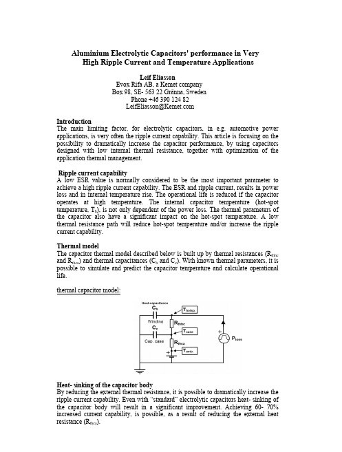
Aluminium Electrolytic Capacitors' performance in Very High Ripple Current and Temperature ApplicationsLeif Eliasson Evox Rifa AB, a Kemet company Box 98, SE- 563 22 Gränna, Sweden Phone +46 390 124 82 LeifEliasson@ Introduction The main limiting factor, for electrolytic capacitors, in e.g. automotive power applications, is very often the ripple current capability. This article is focusing on the possibility to dramatically increase the capacitor performance, by using capacitors designed with low internal thermal resistance, together with optimization of the application thermal management. Ripple current capability A low ESR value is normally considered to be the most important parameter to achieve a high ripple current capability. The ESR and ripple current, results in power loss and in internal temperature rise. The operational life is reduced if the capacitor operates at high temperature. The internal capacitor temperature (hot-spot temperature, Th), is not only dependent of the power loss. The thermal parameters of the capacitor also have a significant impact on the hot-spot temperature. A low thermal resistance path will reduce hot-spot temperature and/or increase the ripple current capability. Thermal model The capacitor thermal model described below is built up by thermal resistances (Rthhc and Rthca) and thermal capacitances (Ch and Cc). With known thermal parameters, it is possible to simulate and predict the capacitor temperature and calculate operational life. thermal capacitor model:Heat- sinking of the capacitor body By reducing the external thermal resistance, it is possible to dramatically increase the ripple current capability. Even with “standard” electrolytic capacitors heat- sinking of the capacitor body will result in a significant improvement. Achieving 60- 70% increased current capability, is possible, as a result of reducing the external heat resistance (Rthca).New capacitor generation - significant performance gain Evox Rifa has introduced a new generation of axial capacitors. The PEG 220-226 series of capacitors, are designed with 50- 70% reduced internal thermal resistance, ( Rthhc, this compared with all other comparable axial capacitors available on the market ). The low thermal resistance is achieved by metallic contact between the catholic foil and bottom of the capacitor casing. The winding is mounted with axial pressure ⇒ Metallic contact between the cathode foil and the bottom of case, resulting in low thermal resistance Winding tabs, welded to bottom of capacitor Bottom of capacitor case (cut) Winding with extended cathodic foilCapacitor, extended cathode designFAxial force on the Al-deck, gives pressure to the winding The extended cathode technology has during decades been in use for large Alelectrolytic screw terminal capacitors. High power applications in cars, now brings similar requirements also for smaller capacitors. Winding with extended cathode, together with other improvements, results in a significant increase in ripple current capability. Up to 28A ripple current, continuous load, is possible to specify, at a capacitor case temperature of 125ºC (∅20x 43mmcase). To achieve this performance the capacitor body needs to be heat- sinked. As a comparison, the ripple current for some of the best capacitors on the market today is 14-15 A (heat- sinked, 125ºC, same case-size). Example - Continuous load: Capacitor ripple current: 26.7A, ≥5 kHz. (Cont. load). Applied DC voltage: ≤ 18VDC Application chassis temp.: 116.7ºC. External thermal resistance (cap. body to metallic chassis): Rthca= 1.6 ºC/W This value is achievable by heat sinking approximately one third of the capacitor body, using thermal conductive paste or glue.Capacitor article, fulfilling above requirements: PEG 225 HJ4480Q ( 4800µF, 25V, ∅20x 35mm), ESR(≥5kHz, ≥125ºC)= 7.3mΩ (max), Rthhc= 2.4ºC/W (internal thermal resistance) Calculated temperatures and operational life (Lop): Power loss: 26,72x 0.0073= 5.2 W, Steady state, thermal conditions (cont. load): Cap. case temp. (Tc): 116.7ºC+ 5,2W* 1.6 ºC/W= 125ºC. Capacitor, hot-spot temperature (Th =winding temp.): 116.7ºC+ 5.2W* (2.4+1.6) ºC/W= 137.5ºC. Operational life for an electrolytic capacitor is direct related to the capacitor hot-spot temperature (max winding temperature). The above described capacitor type is capable of minimum 4 kh operational life at described conditions ( ⇒ Th= 137.5 ºC). Test results and experience verify that the operational life (Lop, minimum) can be described by following formula:( 12ºC decreased temperature results in an factor of 2 longer operational life. Specified Lop for PEG 225 is 85kh at Th= 85ºC and 2 kh at 150ºC) Test results, verifying capacitor specification [ accelerated test, 12ºC increased temperature compared with specified temp., at rated ripple current ]: Tested capacitor article: PEG 225 HJ4480Q, Test conditions, as described in above example but tested at 12 ºC higher temperature⇒ Case temperature 137 ºC, hot-spot temperature 149,5 ºC. Ripple current load: 27 A. Test duration: 2000 h Parameter change after test: ∆Cap (µF) -6,4% -5,3% -10,8% ∆tan d (%) +8,1% +45% -4,5% ∆ESR(100kHz) +5,2% +23% ±0,0%mean max minComments: The capacitor specification are fulfilled, also after 2000h at accelerated conditions. [at +12 ºC increased temp] Example, Intermittent load (simulation and measurements): 50% Duty Cycle, 40A, 5kHz, 30s “on”, 30s “off”, applied DC voltage: 16V, application chassis temperature: 117ºC Capacitor mounted with low thermal resistance path, to metallic chassis, Rthca= 1.6 ºC/W.Capacitor article: PEG 226 KL 4270Q ( 2700µF, 40V, ∅20x 43mm), ESR(>5kHz, >125ºC)= 6.7mΩ (max), Rthhc= 2.4ºC/W, Ch=18.4 ºC/ J, Cc=4.6 ºC/ J Thermal simulation:Calculated hot-spot temperature (Th) and capacitor case temperature (Tc) Verifying measurement, intermittent load 50% Duty Cycle, 40A, 5kHz, 30s “on”, 30s “off”, applied DC voltage: 16V, PEG 226 KL 4270Q ( 2700µF, 40V, ∅20x 43mm)Measurements, intermittent load, (50%, 40A, 5kHz) (Case temperatures, two capacitors):Parametric changes after 1000h of intermittent operation: ESR (100kHz, 20º): + 3.5%, Capacitance (100Hz, 20º): -2.5%. Remark: The capacitors still fulfil the specification for new capacitorsTest set-up, capacitors mounted with low thermal resistance path, to metallic chassis: Summary In high ripple current applications like automotive power, it’s possible to gain a significant advantage by using capacitors designed with optimized thermal parameters. Further significant improvement is possible to achieve by heat-sinking the capacitors.。
IC基本电气特性-华为内部员工培训资料
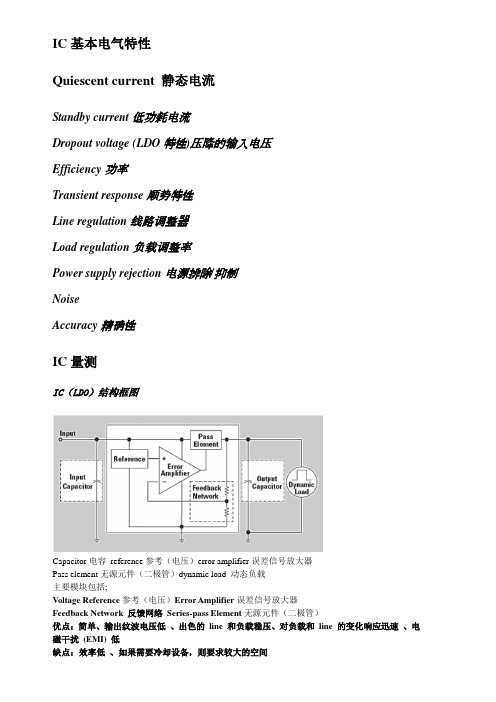
IC基本电气特性Quiescent current 静态电流Standby current低功耗电流Dropout voltage (LDO特性)压降的输入电压Efficiency功率Transient response顺势特性Line regulation线路调整器Load regulation负载调整率Power supply rejection电源排除/抑制NoiseAccuracy精确性IC量测IC(LDO)结构框图Capacitor电容reference参考(电压)error amplifier误差信号放大器Pass element无源元件(二极管)dynamic load 动态负载主要模块包括;Voltage Reference参考(电压)Error Amplifier误差信号放大器Feedback Network 反馈网络Series-pass Element无源元件(二极管)优点:简单、输出纹波电压低、出色的line 和负载稳压、对负载和line 的变化响应迅速、电磁干扰(EMI) 低缺点:效率低、如果需要冷却设备,则要求较大的空间IC基本电气特性-Quiescent Current & Standby CurrentQuiescent Current(Ground current):The difference between input and output。
Low quiescent current is necessary tomaximize the efficiency.低静态电流是最大限度地提高效率必要条件。
Standby Current:The input current drawn by a regulator whenthe output voltage is disabled by a shutdownsignal.Quiescent Current and Output CurrentThe value of quiescent current is mostly determinedby the series pass element, topologies, ambienttemperature, etc.静态电流的值主要是一系列无源元件,拓扑结构,环境温度等确定的具体特性与IC结构、制程密切相关IC基本电气特性-Dropout V oltage(特有规格)◆Low-Dropout Linear Regulators低压差线性稳压器◆传统的三端稳压器如:LM78xxVdrop的典型值是2V,看到很多7805应用时都会背着一个散热器。
PMLSM的改进型模糊直接推力控制

PMLSM的改进型模糊直接推力控制摘要:为了解决传统DFC系统存在的磁链控制不对称及较大推力脉动等问题,提出了将扇区细分与模糊控制相结合的改进型模糊直接推力控制(DFC)系统。
建立了永磁直线同步电机(PMLSM)改进型模糊直接推力控制系统的数学模型,利用Matlab/Simulink对整个系统的运行状态进行了仿真。
实验结果证明改进型模糊DFC方法能够有效改善磁链轨迹,减小脉动,提高系统控制性能。
关键词:永磁直线同步电机模糊直接推力控制扇区细分直接推力控制(DFC)是在直接转矩控制(DTC)的基础上发展起来的,专用于直线电机传动系统的控制方法[5]。
传统DTC采用滞环比较的方式控制磁链及推力,容易导致转矩响应迟钝,造成转矩脉动增大。
为改善DTC系统性能,国内外学者对其进行了大量的研究工作,文献[1]采用模糊控制器取代滞环比较的方式,这种方法通常缺少精确的确定依据;文献[2]针对异步电机DTC控制,提出把传统的6扇区控制改为12扇区,以改善控制性能,但是控制效果不明显。
本文通过对传统DFC中的磁链和推力脉动进行分析,提出了模糊DFC策略,同时根据模糊DFC的基本原理,将扇区细分与模糊控制器相结合,设计出改进型模糊控制器,重新设计了隶属度及控制规则。
1 系统基本结构及数学模型1.1 PMLSM的数学模型2 改进型模糊DFC系统为克服传统DFC系统中通过滞环比较器及开关表选择电压空间矢量而造成的较大的磁链和推力脉动,本文将模糊控制器取代滞环比较器,通过模糊逻辑将初级磁链与推力差值的大小进行模糊分级,并结合初级磁链位置信息根据不同等级作不同决策来优化空间电压矢量的选择。
经文献[7]分析可知,磁链增量在传统6扇区划分中,将体现出每隔20°的明显不对称特性,这将造成所需要达到的圆形磁链轨迹不够标准,从而影响控制精度。
因此,较为合理的方式是将原来的6扇区模式细分为18扇区。
本文将扇区细分与模糊控制相结合,设计出扇区细分后的模糊控制规则,形成改进型模糊控制器,从而达到改善直接推力控制性能的目的。
UCC28070 300W Interleaved PFC Pre-regulator Design Review
-
1
= 0.55
DIL = POUT ´ 2 × 0.3 = 300W ´ 2 ´ 0.3 » 3.0 A VIN_MIN ´ h ´ K(DPLL ) 85V ´ 0.90 ´ 0.55
L1 = L2 = VIN_MIN ´ 2 ´ DPLL = 85V ´ 2 ´ 0.69 » 140 uH
DIL × fs
ABSTRACT In higher power applications to utilize the full line power and reduce line current harmonics PFC Pre-regulators are generally required. In these high power applications interleaving PFC stages can reduce inductor volume and reduce input and output capacitor ripple current. This results in smaller overall magnetic volume and filter capacitor volume increasing the converters overall power density. This is made possible through distributing the power over two interleaved boost converters and the inductor ripple current cancellation that occurs with interleaving, reference [5]. This application note will review the design of a 300W two-phase interleaved power factor corrected (PFC) pre-regulator. This power converter achieves PFC with the use of the UCC28070 interleaved PFC controller, reference [7].
开关电源输入输出电容的选择
1.2
Selecting Input Ceramic Capacitors
Load current, duty cycle, and switching frequency are several factors which determine the magnitude of the input ripple voltage. The input ripple voltage amplitude is directly proportional to the output load current. The maximum input ripple amplitude occurs at maximum output load. Also, the amplitude of the voltage ripple varies with the duty cycle of the converter. For a single phase buck regulator, the duty cycle is approximately the ratio of output to input dc voltage. A single phase buck regulator reaches its maximum ripple at 50% duty cycle. Figure 1 shows the ac rms, dc, and total rms input current vs duty cycle for a single phase buck regulator. The solid curve shows the ac rms ripple amplitude. It reaches a maximum at 50% duty cycle. The chart shows how this magnitude falls off on either side of 50%. The straight solid line shows the average value or dc component as a function of duty cycle. The curved dashed line shows the total rms current, both dc and ac, of the rectangular pulse as duty cycle varies.
汉英沉积学常用词汇

附录:汉英沉积学常用词汇凹坑pool,chute白垩chalk白云化灰岩dolomitized limestone白云母muscovite白云石dolomite白云岩dolostone, dolomitite斑点构造mottled structure斑礁patch reef斑晶porphyrotope斑脱岩bentonite搬运作用transportation板状晶体laths半深海helmipelagic半自形晶subhedral棒形蛀木虫迹teredolites clavatus包卷层理convolute lamination包卷构造comvolute structure堡礁(障壁礁) barrier reef抱球虫软泥globigerina ooze比拟试验模式scaled experimental model碧玉jasper边滩point bar辫状河braided channel标志层key bed标准偏差standard deviation表面结构surface texture表皮鲕superficial Oolits表栖动物epifauna表生成岩作用epidiagenesis表生作用epigenesis表土regolith滨湖亚相lake-shore滨面shoreface滨线shoreline冰雹痕hail impression冰川glacier冰-海沉积物glacier-marine sediment冰川相glacial facies冰碛物till冰碛岩tillite冰水沉积outwash波长wave length波高wave height波痕ripple波状层理wavy bedding剥离线理parting lineation不等粒inequigranular不整合unconformity槽痕flute槽模flute casts侧向沉积作用lateral sedimentation侧向加积lateral accretion测井沉积学well-logging sedimentology 测井相electrofacies层bed层间流interflow层孔虫stromatoporoid层理stratification,bedding,lamination 层流laminar flow层内溶解作用intrastratal solution层系set层系组coset层序地层学sequence stratigraphy次长石净砂岩subarkose次生孔隙secondary porosity次岩屑净砂岩sublitharenite长石feldspar长石砂岩feldspar sandstone长石净砂岩arkose长石净砂岩类arkosic arenite长石杂砂岩feldspathic greywacke长石杂砂岩类arkosic greywacke潮道tidal channel潮间带intertidal潮控三角洲tidal-dominated delta潮坪tidal flat潮上带supratidal潮汐层理tidal- bedding潮汐流ebb current潮汐三角洲tidal delta潮下带subtidal zone沉积分异作用sedimentary differentiation 沉积构造sedimentary structure沉积后作用postdeposition沉积环境depositional environment沉积模式sedimentary model沉积盆地sedimentary basin沉积铁矿sedimentary iron ores沉积物sediment沉积物重力流sediment gravity flow沉积相sedimentary(depositional)facies 沉积学sedimentology沉积岩sedimentary rocks沉积岩石学sedimentary petrology沉积作用sedimentation,deposition成分成熟度compositional matuarity成岩作用diagenesis赤铁矿hematite冲积平原alluvial plain冲积扇alluvial fan冲裂avulsion冲流swash冲流回流带zone of swash and backwash 冲刷痕scour mark冲洗交错层理swash bedding冲溢扇washover fan储层reservoir储油窗oil –windows床沙bed床沙形体bed form床沙载荷bed load吹程fetch垂向沉积作用vertical accretion丛藻迹chondrites粗砾cobble粗枝藻门dasyclads大潮spring tide大陆架continental shelf大陆隆continental rise大陆坡continental slope大洋盆地basin带穴迹taenidium带状迹teanidium袋状钻孔迹rogerella单杯迹monocraterion单成份砾岩oligomictic conglomerate 岛(弧)-海(沟)体系arc-trench system 岛弧island arc等深流contour current等深积岩contourite等趾迹isopodichnus等足迹isopodichnus低镁方解石low-magnesian calcite低弯度河道low-sinuosity channel低位体系域low-stand systems tract 堤岸bank底痕sole mark底积层bottomset底模solecast底栖生物benthos底载河道bedload channel地层strata地层倾斜录井dipmeter log地层水formation water地球化学geochemistry地球物理geophysics地震地层学seismic stratigraphy地震勘探seismic exploration递变层graded layer递变悬浮作用graded suspension典型浊积岩clastic turbidite电测井electric log叠层石stromatolite叠瓦状排列imbricate arrangement 顶积层topsets动态模式dynamic model动藻迹zoophycus豆粒pisolite段member对称波痕symmetrical ripple鲕粒oolite二叶石迹cruziana反递变层理reverse grading反沙丘层理antidune bedding反向递变的inversely graded泛滥盆地flood basin泛滥平原flood plain方沸石Analcime方解石calcite放射虫Radiolarians放射性测井radioactivity log非补偿(饥饿)沉积starved basin 非显晶质的aphanitic沸石zeolite分流河道distributary channel分流河口砂坝distributary-mouth bar 分流间湾interdistributary分选系数So分选作用sorting粉砂silt粉砂岩siltite,siltstone粉砂页岩silt shale球粒pellet风暴大潮storm surge风成eolian风成波痕eolian ripple,wind ripple风成交错层理aeolian cross bedding风成岩eolianite风化作用weathering风生流wind-drift current风蚀deflation峰度curtosis缝合线stylolite弗劳德数Froude number浮游生物plankton腐泥sapropel负载(荷)构造load structure复成分砾岩polymictic conglomerate复理石flysch钙结层caliche干酪根kerogen干盐湖playa高岭石kaolinite高弯度河道high-sinuosity channel高位体系域high-stand systems tract根珊瑚迹rhizocoralliun耕作迹agrichnia沟模groove casts沟蠕形迹taphrhelminthopsis古拉迹paleohelcura古生态学paleoecology古生物paleontological古水流标志paleocurrent indicator古土壤paleosols古网迹palaeodictyon古斜坡paleoslope骨架岩framestone固着底栖生物sessile benthos光合作用photosynthesis硅镁层sima硅土,二氧化硅silica硅质silic-硅质碎屑siliciclastic国际沉积学家学会IAS(International Association of Sedimentologists) 海(湖)泛面flooding surface海(湖)滩beach海岸带coastal zone海底扇submarine fan海底峡谷submarine canyon海沟trench海进体系域transgressive systems tract 海浪sea wave海绿石glauconite海平面变化sea-level changes海平面升降eustasy海侵transgression海侵层序transgressive sequence海生迹thalassinoides海滩marine beach海滩脊ridge of a beach海相三角洲marine delta海洋ocean旱谷arroyo, wadi河床(道)channel河床滞留lag河底滞留沉积channel floor lag河控三角洲fluvial delta河口湾estuary河流相fluvial河漫overbank核形石oncilite褐铁矿limonite黑色页岩black shale黑云母biotite红藻植物门rhodophyta后滨backshore后成作用katagenesis,anadiagenesis弧间盆地interarc basin弧内盆地intra-arc basin弧前盆地forearc basin湖lake湖泊环境lacustrine environment湖泊相lacustrine湖面波动seiche湖沼学limnology滑[动]痕slide mark滑塌构造slump structure滑塌岩slumps还原硫酸盐细菌desulfouibrio,desulfomaculmi 还原作用reduction环境沉积学environmental sedimentology环线迹spirorhaphe黄铁矿pyrite黄土loess灰泥micrite灰泥岩mudstone灰质白云岩calcareous dolostone回流backflow,backwash混杂沉积岩diamicton混杂堆积物mélange混载荷流mixed-load channel火山弹bomb火山灰ash火山灰流ash flow火山角砾岩volcanic breccia火山块block火山泥石流lahar火山碎屑pyroclastic debris,tephra火山碎屑流pyroclastic flow火山碎屑岩pyroclastic rock火焰构造flame structure鸡笼状的chickenwire集合粒aggregate集块岩agglomerate加积accretion加积作用aggradation假亮晶pseudospar尖峰度的jeptokurtic剪切shearing交错层cross beds交错层理cross bedding; cross stratification交错纹crossed-lamellar交错纹层cross laminae胶结物cement胶结作用cementation胶磷矿collophane礁reef礁核reef core礁后相backreef facies礁麓堆积reef talus礁前相forereef facies礁相reef facies角度不整合angular unconformity 角砾岩breccias节藻迹phycodes结晶碳酸盐岩crystalline carbonate 界面bounding surfaces金藻门chrysophyta津(波)浪tsunami近滨nearshore进潮口tidal inlet进积作用progradation进食构造feeding structures进食迹fodinichnia晶面crystal face晶体crystal井形穴shafts净砂岩arenite静态模式static model居住构造dwelling structure居住迹domichnia居住潜穴dwelling burrows巨画迹megagrapton巨砾boulder决口扇crevasse,crevasse splay 均匀悬浮uniform suspension颗粒grain ,particle颗粒流grain flow颗粒岩grainstone颗粒支撑的particle -supported ,grain-supported 可劈性fissility可容空间accommodation space克拉通craton孔隙(度)pore,porosity块状层理massive bedding块状砂岩massive sandstone浪成波痕wave-generated ripple浪成沙纹层理wave- ripple bedding浪基面wave base浪控三角洲wave-dominated delta雷诺数Reynolds number-Re类沙蚕迹nereites累积频率曲线cumulative-frequency curve离岸(裂)流rip current犁沟迹aulichnites丽线迹cosmorhaphe砾gravel砾漠reg砾屑灰岩calcirudite砾屑岩rudite砾岩conglomerate粒度grain size粒度概率图probability plot粒度中值Md粒间孔隙度intergranular porosity粒屑灰岩grainstone粒序层理graded bedding亮晶sparite亮晶方解石sparry calcite亮晶灰岩sparite亮煤clarain裂隙fracture临滨shoreface磷灰岩phosphorite磷酸盐岩phosphate rock菱铁矿siderite流动体制flow regimes流痕rill impression流态flow regime流体化作用fluidization硫酸盐sulphate漏斗形funnel shape陆表海epicontinental sea陆架边缘体系域shelf margin systems tract 陆相terrestrial陆缘海marginal sea陆源碎屑岩terrigenous clastic rocks陆表海epeiric sea绿泥岩chlorite绿藻门chlorophyta,卵石质砂岩pebbly sandstone螺管迹gyrolithes洛伦茨迹corenzinia脉状层理flaser bedding漫流sheet flow漫游迹planoliies煤coal煤化作用coalification锰质岩manganess rock觅食迹pascichnia觅食拖迹grazing trails密度底流density underflow密度流density current密度跃层pycnocline磨拉石molasses母岩source rock, parent rock母岩区provenance,source area内成岩endogenetic内栖动物infauna内碎屑intraclast钠长石albite钠长石化albitization能量带energy belt泥mud泥板岩argillite泥晶micrite泥晶套micrite envelope泥粒灰岩(泥质颗粒岩)packstone 泥裂mud crack泥流mud flow泥石流debris flow泥质岩mudrock泥页岩argillutite泥支撑的mud supported泥质的argil拟蠕形迹helminthopsis逆行沙波regressive sand wave逆行沙丘antidune年代地层单位chronostratigraphic unit 鸟眼构造birds-eyes structure鸟足状三角洲bird-foot delta凝灰岩tuff凝聚颗粒aggregate grains凝块灰岩thrombolite牛顿流体Newtonian fluid牛轭湖ox-bow lake爬迹repichnia爬升沙纹层理climbing ripple bedding 爬行crawling拍岸浪surf盘旋虫科spirillinidae螃蟹迹psilonichnus跑动running泡沫痕foam impression盆内岩intrabasinal rock盆外岩石extrabasinal rock片流sheetwash偏度Sk1,skewness漂砾erratic平均粒径Mz平均值mean平行层理parallel bedding平直河straight channel破浪breaker破浪带breaker zone葡萄石grapestones气候带climate belts牵引[作用] traction牵引流tractive current牵引毯状沉积traction carpet前滨foreshore前积层foresets前三角洲沉积prodelta deposit浅海区neritic province浅滩shoal墙形迹teichichus丘状交错层理hummocky cross bedding球度sphericity球粒pellet,pellet peloids球状粒peloid曲带迹curuolithus曲流meander曲流裁直neck cutoff曲流河meandering river取心钻井core drilling全球海平面变化eustatic change of sea level 缺氧事件anoxic event群group群体生物colony(organisms)热云nuee ardente热云岩ignimbrite溶解载荷solutional load熔结凝灰岩ignimbrite蠕形迹helminthoida软流圈asthenosphere软泥ooze弱光带disphotic zone萨布哈(盐沼)sabkha三角洲delta三角洲平原delta plain三角洲前缘delta front三联点triple junction扫毛虫sabellarians沙坝bar沙波sand wave沙流sand flow沙漠desert沙漠相desert facies沙丘dune沙蜀迹arenicolites沙体Sand body沙纹ripples沙嘴spit砂sand砂火山sand volcanoes砂流sand flow砂屑detritus砂屑灰岩calcarenite砂岩sandstone砂枕构造pillow structure 筛状沉积sieve deposition 山鹿冲积平原bajada山麓piedmont珊瑚coral扇砾岩fanglomerate扇三角洲fan delta扇状三角洲fan-like delta 舌菌迹glossiofunhites蛇形迹ophiomorpha深海pelagic, deep sea深海带abyssal zone深海沟deep-sea trench深海平原abyssal深海扇deep-sea fan深泓线thalweg深水bathymetric深水盆地bathymetric basin渗透率permeability生长构造growth structure生物层biostrome生物带biozone生物地层学biostratigraphy生物灰岩biolithite生物礁reef生物颗粒bioclast生物亮晶灰岩biosparite生物内碎屑bioclastic生物泥晶灰岩biomicrite生物丘bioherm生物扰动作用bioturbation生物遗迹化石trace fossil石膏gypsum石化作用lithification石灰岩limestone石漠hamada石英quarts石英砂岩quartz sandstone,silicarenita 石英净砂岩quartz arenite石英杂砂岩quartzwack石针迹skolithos石枝藻litho-thammium始成岩作用eodiagenesis示顶底标志geopetal criterion事实模式actual model数学模式mathematical model刷模brush casts双杯迹diplocraterion双形迹dimorphichus双趾迹diplichifes水道channel水流current,aqueous flow水流痕current mark水流上涌upwelling水流线理current lineation水平层理horizontal bedding水体分层stratification of the water column水下泥石流subaqueous debis flow水下岩崩subaqueous rockfall水悬浮作用aqueous suspension斯科阳迹scoyenia似海生迹thalassinoides似海星迹asteriacites似蠕形迹helminthopsis似藻迹phycodes碎屑颗粒detrital particle燧石flint ,chert他生沉积物allochthonous sediments它形晶anhedral塌积角砾岩collapse braccia塔斯曼迹tasmanadia台地platform苔藓虫fenestrate bryozoans滩bank滩脊beach ridge碳酸盐carbonate碳酸盐岩carbonate rock, carbonatite碳酸盐岩补偿深度carbonate compensation depth 碳酸盐岩隆(建隆)carbonate buildup逃逸构造escape structure逃逸迹fugichnia体系域systems tract天然堤levee,natural levee填集作用packing跳模bounce casts跳跃作用saltation铁岩ironstone铁质岩ferruginous rock停息迹cubchnia同沉积滑塌构造syndepositinal slump structure同生白云岩syngenetic dolostone同生作用syngenesis透光带photic zone透镜状层理lenticular bedding湍流turbulent flow团块lumps退覆层序offlap sequence洼状交错层理swaley cross bedding外成岩exogenetic rock外来岩块exotic block外生沉积物exogentic sediments弯曲锚形迹ancorichnus coronus晚成岩作用telodiagenesis网状(交织)河流anastomosing stream,anastomosed river 微亮晶microspar微斜长石microcline胃形钻孔迹gastrochaenolites温跃层thermoclime纹层laminae,lamination纹层状的laminated纹理lamination纹泥,季节泥varve雯石(霰石)aragonite紊流turbulent flow无光带aphotic zone无粘结性颗粒cohesionless particle物源区provenance矽藻diatom细砾granule线管迹tigllites相facies相变facies change相标志facies mark相对海平面relative sea-level相序facies sequence (succession)向上变粗coarsening-upward向上变浅shoaling-upward,shallowing--upward小潮neap tide小间断diastem斜坡地形clinoform泄水构造water-escape structure泻湖lagoon新生变形作用neomorphism新月形沙丘barchan dune信风trade winds星瓣迹asterosoma休息迹resting traces悬浮(移)负载suspended load选择交代作用selective replacement压扁层理flaser bedding压刻痕toll mark压溶作用pressure solution压实作用compaction盐水楔saltwater wedge岩石地层单位lithostratigraphic unit岩石地层学lithostratigraphy岩石圈lithosphere岩石学petrology岩相lithofacies岩相古地理lithofacies paleogeography岩屑rock fragment,lithic岩屑砂岩lithic sandstone,rock fragment sandstone 岩屑净砂岩litharenite岩屑杂砂岩lithic greywacke岩屑质长石净砂岩lithic arkose岩性lithological沿岸流longshore current沿岸沙坝longshore bar盐度salinity盐湖salt lakes盐碱滩salina氧化作用oxidation页岩shale液化liguefaction液化沉积物流fluidized sediment flow液化作用liquefaction伊利石illite遗迹化石ichnofossil,trace fossil遗迹相ichofacies异化颗粒allochem粘结灰岩bindstones硬砂岩greywacke硬石膏anhydrite涌浪swells尤尔斯特龙图解Hiulstrom diagram油气储层地质建模reservoir geological Modeling 油页岩oil shale游泳生物nekton organisms原生孔隙primary porosity有效孔隙度effective porosity羽状交错层理herringbone cross bedding雨痕rain impression原始古网迹protopalaeodictyon圆度roudness越岸沉积overbank deposit运动迹moving traces韵律层理rhythmic bedding杂基matrix杂基支撑matrix supported杂砂岩graywacke,wacke载荷load再作用面(复活面)reactivation surface藻管迹phycosiphon藻类algae藻团块algae lumps藻团粒algal poliods藻席Algal mats造礁珊瑚hermatypic coral粘度viscosity粘结岩boundstone粘土级clay size粘土矿物clay mineral粘土岩claystone涨潮流flood current帐篷构造tepees障壁barrier障壁岛barrier island障壁沙咀barrier spit障积岩bufflestone沼泽相swamp振荡波痕oscillation ripples蒸发岩evaporites正常鲕normal Oolits正递变的normally graded正化颗粒orthochems正态分布normal distribution直观模式visual model指状沙坝bar-finger sand指状钻孔迹trypanites中成岩作用mesodiagenesis中峰度的mesokertic中砾pebble中值median钟形bell shape众数mode重晶石barite重流层heavy-fluid layer皱饰迹rusophycus蛀木虫迹teredolites铸模mold铸模孔隙moldic porosity铸型cast锥模prod casts坠积物colluvium准层序parasequence准层序组parasequence set浊积石灰岩allodapic limestone浊积岩turbidite浊流turbidity current自生沉积物autochthonous sediments 自生的authigentic自形晶euhedral自悬浮autosuspension 组formation组构fabric钻孔迹trypanites。
无刷直流电机控制器的软件设计中英文翻译(精)
Commutation Torque Ripple Reduction in BLDC Motor Using PWM_ON_PWM ModeGuangwei Meng, Hao Xiong, Huaishu Li Department of Electrical Engineering, Naval University of Engineering, Wuhan, China.Abstrac t:The paper analyzes the steady commutation process of the BLDC motor using PWM mode, confirms the commutation time to keep noncommutation phase current amplitude constant during commutation period by way of PWM in the period to implement the compensation control to eliminate commutation torque ripple under both low speed and high speed operation, investigates the effect by PWM mode on a three-phase six-state 120°turn-on BLDC motor, and presents torque ripple compensation control in PWM_ON_PWM mode, which can not only entirelyeliminate torque ripple resulted from the current emerging in the turn-off phase during non-commutation period but also compensate torque ripple caused by the commutation current during commutation period.Index Terms—BLDC motor, commutation, PWM, torque ripple.I. INTRODUCTIONThe BLDC motors have been widely used due to its features - a simple structure, good speed adjusting performance,high power density, low noise and simple control, etc. It is a hotspot to suppress the torque ripple and improve the control performance of a BLDC motor with the trapezoidal back emf.BLDC motors usually operate in all kinds of PWM modes, which not only affect the dynamic loss of power switches and radiation uniformity, but also influence the torque ripple. It is an effective way to suppress the torque ripple through changing dc bus chopper control to remain non-commutation phase current amplitude constant, but it results into a more complex topology [1]-[3]. It is just fit for low speed applications tocontrol non-commutation phase current amplitude to regulate the commutation torque ripple . It is analyzed about the influence resulted from PWM ON mode on the torque ripple .The ideas in [1]-[3] are to adopt different suppression methods in different speed interval, but they don’t take t he effect by PWM mode s on the systemin account. The predictive current, neural network control and active disturbance rejection control etc are introduced to suppress the torque ripple , but the control algorithm is more complicated and harder for realization.Depending on the commutation process of BLDC motors and the effect by PWM modes on the system, thepaper presents a torque ripple com-pensation control inPWM_ON_PWM mode at different speeds by seeking different PWM modulation ratios during commutation period as motor runs at low speed and high speed.The method retains the original to-pology, improves the control performance of the system dramatically,and moreover is easy to realize.II. ELECTROMAGNETIC TORQUE OF BLDC MOTORDURING COMMUTATION PROCESSAssume that the BLDC motor is three-phase symmetrical and Y- connected, and neglect eddy currents and hysteresis losses, its equivalent circuit and main circuit are shown in Figure 1. r, L are the resistance andinductance of the stator windingsrespectively;C B A e e e ,, are the counter emfs of the corresponding phase windings respectively; C B A i i i ,, are the corresponding phase currents respectively.0=++C B A i i i (1The counter emf of every phase winding is a trapezoidal waveform with a flat-top width greater than or equal to 1200 electrical degree,and its flat-top amplitude is Em. When the motor works in three-phase six-state 1200 turn-on mode, the currents don’t commutates instantaneously as a result of the inductanceof the armature winding. Take the power switch 1T and 2T ’s turn-on to2T and 3T ’s turn -on for example. During the commutation, it is gained as follows m C B A E e e e =-== (2Suppose that the mechanical angular velocity of the rotor is Ω, the toque can be obtained as follows during the commutation process.Ω=Ω++=C m C C B B A A e i E i e i e i e T 2 (3 It is obvious from (3 that the toque is proportional to the non-commutation phase current during commutation,i.e. the commutation torque ripple can be eliminated so long as non-commutation phase current remains constant during commutation. III TORQUE RIPPLE REDUCTION IN PWM MODEa new PWM mode is presented -PWM _ON _PWM, i.e. using PWM mode in the first30°and the last 30° while keeping constant turn-onmode in the middle 60°. The mode can entirely eliminate the emerging current in the turn-off phase during non-commutation and thus reduce the torqueripple during non-commutation.PWM _ON _PWM is a bilateral modulation, but the dynamic losses of power switches in the mode are equal to those of unilateral modulation. Six switches are modulated in turn, so the power switches have a uniform radiation and the system has a higher reliability. The mode is employing PWM on the turn-on power switchesand thus it can suppress the torque ripple during commutation to a certain extent even if a compensation control is not applied at a low speed.In PWM _ON _PWM mode, it can not only eliminate the torque ripple during non-commutation but also suppress the commutation torque ripple at low speed operation by keeping dm BB U rI E D 034+= in the commutation compensation control time ⎪⎪⎭⎫⎝⎛++=m c E rI rI r L t 21ln 00 at low speed operation, i.e.d m U rI E ≤+034.At high speed operation i.e.d m U rI E ≥+034,overlapping commutation is used to keep the turn-on phase constantly on and make the control pulse duty cycle of the turn-off phase 1340-+=dm AA U rI E D in the commutation compensation control time⎪⎪⎭⎫⎝⎛----=0021ln rI E U rI r L t m d c ,which can not only eliminate the torque ripple during noncommutation but also suppress the commutation torque ripple at high speed operation.A simulation is carried out to verify the method.The parameters areN T m r n V U m kg J r mH L L N N 4.0,1600,48,0157.0,66.0,262===⋅=Ω==.In non-full-bridge modulation mode such as H_PWM-L_ON mode, power switches in the upper arms use PWM mode while the others in the lowerarms use constant turn-on mode in 1200 turn-on interval. The simulation waveform of phase current is shown in Fig. 3. It is obvious that a current emerges in the turn-off phase during non-turn-on period and its pulsating frequency is the same as the modulatingfrequency while its amplitude varies with the variation of back emf amplitude, whichproduces a reverse torque.Figure 2 H_ PWM - L_ ON phase current waveform Figure 3 PWM_ON_PWM phase current waveform The simulation waveform of phase current in PWM _ON _PWM mode is shown in Fig.4. It is obvious that no current emerges in the turn-off phase duringnon-turnon period, which reduces the torque ripple during noncommutation compared with other PWM mode.Fig.5 shows the waveforms of the phase current and torque at low speed with PWM pulse duty cycle DA=0.2 without compensation control. Fig. 6 shows thewaveforms of the phase current and torque at low speed with the control pulse duty cycle DBB=0.4 in the turn-on phase within the commutation time tc=0.0013 by a compensation control. The comparison indicates that the torque ripple caused by commutation can be almost eliminated by means of a commutation compensationcontrol at low speed application.It is found from Fig.3 to Fig.8 that using a commutation compensation control in PWM_ON_PWM mode can not only avoid the torque ripple caused by the emerging current in the turn-off phase during noncommutation but also effectively suppress the commutation torque ripple at both low speed and high speed applications.Figure4 phase current and torque waveform during Figure 5 when running at low speed by changing theLow speed running phase current and phase compensation torque waveformFigure 6under the speed of phase current and torque waveform Figure 7high-speed run through the compensation control ofphase current and torque waveformIV. CONCLUSIONSBased on the analysis of commutation process of BLDC motor and the effect by PWM mode on the control system, a commutation compensation control inPWM_ON_PWM mode is worked out, which can not only eliminate torque ripple resulted from the current emerging in the turn-off phase during non-commutation period but also compensate commutation torque ripple. A control system without torque ripple can be realized through the method under both low speed and high speed operation.REFERENCES[1] S. Wang, T. Li, and Z. Wang, “Commutation torque ripple reduction in brushless DC motor drives using a sin gle current sensor,” Electric Machines and Control, vol. 12,pp. 288-293, March. 2008.[2] X. Zhang and Z. Lü, “New BLDCM drive method to smooth the torque,” Power Electronics, vol. 41, pp. 102-104, Feb. 2007.[3] H.J. Song and C. Ick. “Commutation torque r ipple reduction in brushless DC motor drivers using a single DC current sensor,” IEEE Trans. On Power Electr, vol. 19,pp. 312-319, Feb. 2004.[4] G.H. Kim, J. Seog and S.W. Jong, “Analysis of the commutation torque ripple effect for BLDCM fed by HCRPWM-VSI,” Proc. of APEC’92, 1992, pp.277-284. [5] X. Zhang and B. Chen, “The different influences of four PWM modes on commutation torque ripples in brushless DC motor control system,” Electric Machines andControl,vol.7, pp. 87-91, Feb. 2003.[6] D. Chen, Z. Liu and J. Ren et al, « Analysis of effects onBLDCM torque ripple by PWM modes,”. Electrical Drivers, vol.35, pp. 18-20, April 2005.中文翻译用PWM_ON_PWM模式抑制无刷直流电机换相引起的脉动转矩中国武汉海军工程大学电机工程系蒙广伟、雄郝、李怀树编摘要:本文分析了无刷直流电动机采用PWM控制稳定换相的过程,证实了运用PWM模式,在换相时控制非换相相电流有稳定不变的幅度,并进行补偿以消除低速和高速工作下的换相转矩脉动;研究了运用三相六状态的PWM模式120°启动无刷直流电机的方法,并提出基于脉宽调制的PWM模式如何来抑制转矩脉动,PWM 控制不仅可以消除非换相期间由关断电流引起的转矩脉动,还可以补偿换相期间由换相电流引起的转矩脉动。
一种具有低电压穿越能力的单相光伏发电系统
一种具有低电压穿越能力的单相光伏发电系统李承尧;杨勇;朱彬彬【摘要】具有低电压穿越能力的光伏并网系统已成为未来发展的趋势.以单相两级式系统为对象,提出了一种新型控制策略:为了最大限度减少直流母线电压在电网故障期间抬升,直流母线在两级之间灵活控制;在低电压穿越阶段,电网电流采用恒定峰值电流控制方法以避免触发过流保护,其中无功电流的幅值取决于电网跌落的深度;控制同路增加给定并网电流补偿环节,最大限度减少给定并网电流幅值中的两倍频扰动,提高并网电流质量.所提控制策略的稳定性及动态特性得到仿真验证.【期刊名称】《中国电力》【年(卷),期】2016(049)003【总页数】6页(P160-165)【关键词】光伏系统;低电压穿越;直流母线电压控制;恒定峰值电流策略;两倍频扰动补偿【作者】李承尧;杨勇;朱彬彬【作者单位】苏州大学机电工程学院,江苏苏州 215006;苏州大学城市轨道交通学院,江苏苏州215006;苏州大学城市轨道交通学院,江苏苏州215006【正文语种】中文【中图分类】TM615随着经济的快速发展,能源消耗逐年增加,常规能源日益枯竭,环境问题日益突出,迫切需要发展可再生清洁能源[1]。
越来越多的分布式发电系统(DPGS)并入电网使得可再生能源发电在电网中的比重逐年增加。
近几年光伏并网发电系统无论是在安装的数量上还是规模上都得到了长足的发展。
国际能源机构的数据显示估计,光伏发电所占比重在2050年将达到11%[2]。
因此,分布式电源(特别是光伏发电系统)的质量对电网系统的稳定起到至关重要的作用[3-6]。
中国国家电网公司2011年5月6日发布实施的《光伏电站接入电网技术规定》中首次明确对大中型光伏电站提出低电压穿越要求[7],包括:(1)电力系统发生不同类型故障时,当光伏电站并网点考核电压在图1电压轮廓线以上区域时,光伏电站应保证不间断并网运行,否则停止向电网线路送电;(2)对电力系统故障期间没有切除的光伏电站,其有功功率在故障清除后应该快速恢复;(3)低电压穿越过程中光伏电站宜提供动态无功支撑。
LM2941详细资料
VDC
Reverse Polarity DC Input Voltage
RO = 100, VO ≥ −0.6V
−30
−15/−15
V(min)
Reverse Polarity Transient Input Voltage
t ≤ 100ms, RO = 100Ω
−75
−50/−50
V(min)
ON/OFF Threshold Voltage ON
−40°C ≤ TJ ≤ 125°C
Electrical Characteristics—LM2941T, LM2941S, LM2941LD
5V ≤ VO ≤ 20V, VIN = VO + 5V, CO = 22μF, unless otherwise specified. Specifications in standard typeface apply for TJ = 25°C,
5mA ≤ IO ≤ 1A (Note 7)
1.275
1.237/1.211 1.313/1.339
V(min) V(max)
Line Regulation Load Regulation
Output Impedance
Quiescent Current
RMS Output Noise, % of VOUT Ripple Rejection Long Term Stability
and the load. Familiar regulator features such as short circuit and thermal overload protection are also provided.
单相逆变器随机PWM选择性消谐滞环随机扩频方法(英文)
单相逆变器随机PWM选择性消谐滞环随机扩频方法(英文)IntroductionPower electronics plays a vital role in modern-day industries as it enables us to control the flow of electricity. One of the core components of the power electronics industry is a single-phase inverter.A single-phase inverter serves the function of converting DC (Direct Current) power into AC (Alternating Current) power, making it a desirable component in various electronic applications. However, single-phase inverters suffer from high Total Harmonic Distortions (THD) that degrades the power quality. This is due to their design, which involves the switching of high-frequency Pulse Width Modulated (PWM) signals at high voltages in order to create an AC waveform from a DC input signal. The unwanted THD can be a significant problem in variouselectronics applications.In order to mitigate the undesirable effects of high THD, a technique called Selective Harmonic Elimination (SHE) is employed. This technique is used to cancel out specific harmonics to eliminate them from the AC waveform. In this paper, we will discuss the Random PWM-based Selective Harmonic Elimination with Spread Spectrum Modulation technique for single-phase inverters, which involves employing random pulse width modulation with spread spectrum modulation to mitigate THD.BackgroundSingle-phase inverters serve a critical function in a variety of applications, including renewable energy sources, and motor drives. They are made up of inductors, capacitors, and small semi-conductive devices. Single-phase inverters produce an AC voltage with the aid of a DC input source and are used in small-scale applications since they can handle low power levels.PWM is a technique that employs a modulation signal with square waves to alter the width of the pulse. This technique has become an essential part of power electronic systems, and it provides numerous advantages such as versatile output voltage control, low motor torque ripple, and soft starting. PWM is widely used in inverter control to eliminate THD as it enables the direct synthesis of an AC waveform.Selective Harmonic Elimination (SHE) is a technique employed to mitigate THD produced due to high-frequency PWM signals. In this technique, only the required harmonics are synthesized, and all others are eliminated. SHE involves finding the harmonic patterns of the desired waveforms and introducing the required harmonic components while eliminating all the others.Spread Spectrum Modulation has become a widely used method of transmitting signals in various communication applications. This technique reduces the interference between signals by spreading them over a broader bandwidth. Spread Spectrum Modulation has been employed in power electronic applications to mitigate electromagnetic interferences and noise.MethodologyThis paper proposes a novel technique called the Random PWM-based Selective Harmonic Elimination with Spread Spectrum Modulation. The proposed technique employs a random PWM algorithm to modulate the AC waveform and Spread Spectrum Modulation to mitigate THD. In this method, high-frequency PWM signals are synthesized randomly, which eliminates the harmonics that contribute to high THD. Furthermore, the Spread Spectrum Modulation technique is employed inthis method to reduce electromagnetic interference (EMI) and noise in the generated AC waveform.Figure 1: Block diagram of proposed methodThe proposed method's block diagram is shown in Figure 1. The input voltage is fed to a PV array through a DC-DC converter. The output of the DC-DC converter is fed to the proposed single-phase inverter system. The inverter system's output voltage is then connected to a load. A Random PWM-Selective Harmonic Elimination (SHE) algorithm is employed to generate the switching signals for the inverter. Furthermore, a Spread Spectrum Modulation technique is employed to modulate the generated PWM signals.The Random PWM-SHE algorithm is developed using MATLAB software. A software model for the inverter system is also created taking the parameters of the device into consideration. The PWM signal generated is compared with the reference signal to calculate the error signal. This error signal is then fed to the controller, which generates the PWM drive signal. The software system model simulates the output waveform from the inverter, and the THD values are calculated from the simulation results.Results and DiscussionThe proposed method is tested using MATLAB software, and the THD values are measured. The simulated results exhibit a THD value reduction of up to 95% compared to standard PWM-based inverters. Furthermore, the Spread Spectrum Modulation technique employed in this method significantly reduces the EMI and noise generated. The method's effectiveness in mitigating THD and reducing EMI and noise makes it an attractive technique for various electronic applications.ConclusionSingle-phase inverters are essential components in numerous electronic applications. Due to the high-frequency switching of PWM signals employed in inverter systems, they generate high levels of THD that can degrade power quality. In this paper, we presented a novel method employing a Random PWM-based Selective Harmonic Elimination with Spread Spectrum Modulation technique to mitigate THD. The simulation results indicated a THD value reduction of up to 95% compared to standard PWM-based inverters. Furthermore, employing spread spectrum modulation decreased EMI and noise generation, making this an attractive method for various electronic applications. The proposed method can also be extended to three-phase inverters in future research.。
- 1、下载文档前请自行甄别文档内容的完整性,平台不提供额外的编辑、内容补充、找答案等附加服务。
- 2、"仅部分预览"的文档,不可在线预览部分如存在完整性等问题,可反馈申请退款(可完整预览的文档不适用该条件!)。
- 3、如文档侵犯您的权益,请联系客服反馈,我们会尽快为您处理(人工客服工作时间:9:00-18:30)。
Low Frequency Current Ripple Reduction Technique With Active Control in a Fuel Cell Power SystemWith Inverter LoadChangrong Liu,Member,IEEE,and Jih-Sheng Lai,Fellow,IEEEAbstract—A fuel cell power system that contains a single-phase dc–ac inverter tends to draw an ac ripple current at twice the output frequency.Such a ripple current may shorten fuel cell life span and worsen the fuel efficiency due to the hystersis effect. The most obvious impact is it tends to reduce the fuel cell output capacity because the fuel cell controller trips under instantaneous over-current condition.In this paper,the ripple current propaga-tion path is analyzed,and its linearized ac model is derived.The equivalent circuit model and ripple current reduction with passive energy storage component are simulated and verified with exper-iments.An advanced active control technique is then proposed to incorporate a current control loop in the dc–dc converter for ripple reduction.The proposed active ripple reduction method has been verified with computer simulation and hardware experiment with a proton exchange membrane type fuel cell using a multi-phase dc–dc converter along with a full-bridge dc–ac inverter. Test results with open loop,single voltage loop,and the proposed active current-loop control are provided for comparison.Index Terms—Fuel cell power system,fuel cell ripple reduction, low frequency current ripple.I.I NTRODUCTIONW ITH CLEAN operating environment and high energy conversion efficiency,fuel cell is getting more and more attention,especially for the stationary power application.Such an application,either delivering electricity with utility intertie or directly supplying to residential area as a standalone power source,can be used for future distributed generation systems. The main problem is fuel cell output voltage is generally low-voltage dc,but the output load is relatively high-voltage ac.An example system that has been the target development of the U.S. Department of Energy(DOE)Solid-State Energy Conversion Alliance(SECA)is to have a nominal5kW single-phase ac output for residential power system using the low-voltage solid-oxide fuel cell(SOFC),which has an output voltage ranges from 20to50V[1].Some existing commercial-off-the-shelf protonManuscript received August17,2005.This work was supported by the U.S.Department of Energy(DOE)National Energy Technology Labora-tory(NETL)Solid-State Energy Alliance Program(SECA)under Award DE-FC26-02NT41567.Recommended for publication by Associate Editor Z. Chen.C.Liu is with Maxim Integrated Products,Sunnyvale,CA94086USA.i is with the Department of Electrical and Computer Engineering, Virginia Polytechnic Institute and State University,Blacksburg,V A24061-0111 USA(e-mail:laijs@).Color versions of one or more of thefigures in this paper are available online at .Digital Object Identifier10.1109/TPEL.2007.900594Fig.1.Block diagram of a stationary fuel cell power system.exchange membrane(PEM)fuel cells also have their nominalvoltage set at48V and below for either telecommunication orresidential applications.In order for low-voltage dc fuel cell to generate50/60Hz,120/240V ac voltage for residential applications,a dc–dc con-verter is needed to boost the fuel cell voltage to a level that can beconverted to the desired ac output.Fig.1shows such a systemstructure that contains a low-voltage high-current dc–dc con-verter and a dc–ac inverter.The output of the dc–dc converter,or the input of the dc–ac inverter for120V ac is typically200V;and for240V ac is about400V.For a nominal20V,5kW fuel cell under full load condition,thevoltage is20V,and the averagecurrent is250A.The ripple is added on top of the average current with a peakcurrent that tends to overload the fuel cell periodically.The fuelcell can experience nuisance tripping with such a ripple relatedoverload situation.Adding energy storage capacitor either onthe high-side dc bus or on the low-side fuel cell dc bus mayhelp reduce the ripple,but the cost and size of added energystorage component are objectionable when the ripple is reducedto an acceptable boratory test indicated a peak-to-peakripple of34%is obtained with a typical1.2-kW design.Thisripple current component implies that fuel cell requires a powerhandling capability17%higher than its nominal output rating.Current ripple not only affects the fuel cell capacity,but alsothe fuel consumption and life span[2],[3].The results indicatethat the fuel cell not only needs higher power handling capa-bility,but also consumes10%more fuels[2].Furthermore,aspointed out by[3],the100-Hz harmonic current exhibits a hys-teresis behavior with PEM fuel cells.Injecting ripple currentaround this frequency to fuel cell may result in thermal problemamong stacks and impair the stack lifetime.The fuel cell cur-rent ripple reduction is thus a major issue for the fuel cell con-verter design.Reference[4]suggested that the ripple currentbe limited to less than10%.Passive energy storage compensa-tion method was suggested and tested extensively in[5].Ac-tive compensation with external bidirectional dc–dc converter 0885-8993/$25.00©2007IEEEFig.2.Low frequency ripple current generation by a single-phase full-bridge inverter.method was suggested in [6],[7].These methods require exter-nally added components or circuits and are not preferred.In this paper,the mechanism of ripple current propagation is analyzed with the derivation of a linearized ac model.An active ripple reduction technique is then proposed by adding a current loop control into the existing voltage loop control system.This active current loop control does not need to add extra converters or expensive energy storage components.Rather,it cancels the ripple current at the dc –dc converter output before it is propa-gating back.With proper selection of control bandwidth for both inner current and outer voltage loops,the ripple current can be signi ficantly reduced while maintaining a stable dc bus output voltage.The proposed ripple current model and the control loop design guideline were veri fied with computer simulation for a 1.2-kW PEM fuel cell system.A multiphase dc –dc converter [8],[9]along with a full-bridge dc –ac inverter was then built and tested to compare the ripple performance under different oper-ating conditions including open loop,single voltage loop,and the proposed dual loop controls.Test results indicated that under open-loop and single voltage-loop controls,the 17%ripple re-mains unreduced,but under the dual loop control,the ripple was reduced to within 1%.II.L OW F REQUENCY C URRENT R IPPLE G ENERATIONAND P ROPAGATION A.Equivalent Ripple Circuit Model DerivationFig.2shows a single-phase full-bridge dc –ac inverter circuit that has been used in the study.The inverter is implemented with a sinusoidal pulse width modulation (PWM)method at 20-kHz switching to ensure a clean output voltage.With a linear load,the output current has the same 60-Hz frequency and sinusoidal waveshape as the output voltage.The inverter input voltage and current are dc,but the current contains high frequency switching noises and a low frequency ripple component.The ripple com-ponent is considered the recti fication effect through the inverter switches,and thus it appears to be a 120Hz pulsating current.The PWM switching noise is filtered with a high-frequency dcbuscapacitor,,but the energy of the 120Hz ripple is too high to be absorbed.A bulky dc buscapacitorcan then be used to smooth the 120-Hz ripple,but a signi ficant part of the 120-Hz ripple remains and continues to propagate through the entire dc –dc converter and back to the fuel cell.To study the ripple propagation,the entire converter is sim-pli fied in an ac equivalent circuit model,as shown in Fig.3.The inverter looking into from together with its load issubsti-Fig.3.Derivation of low frequency ripple current propagation model.tuted by a 120Hz pulsating currentsource,,and the fuel cell is replaced with a voltagesourcealong with internalimpedance .The filterinductor ,dc buscapacitor,and the inputcapacitor represent the impedances on the propa-gating path.The electrolytic capacitor equivalent series resistors(ESRs)and are included.When the dc –dc converter switching frequency is much higher than the ripple frequency,the dc –dc converter can be treated as an ideal dc –dc transformer.The dc model in Fig.3shows the use of a dc transformer to replace the entire dc –dc converter.Since only ripple components are of interest in the study,the dc voltage source can be shorted,and the primary circuit impedances can be converted to the secondary quantity.Thus a simpli fied ac ripple model can be represented with only the ripple current source and impedances on the propagating path.Here the dc –dc converter can be represented with a simpleresistor.Based on the model shown in Fig.3,the input ripple current from voltage source can be expressed in(1)(1)where is the voltage conversion ratio between output ac peak voltage and low-side fuel cell voltage,andB.Model VerificationEquation (1)provides the insight of the relationship between the input current ripple and load current ripple with all the crit-ical circuit parameters.In the expression,the source impedanceLIU AND LAI:LOW FREQUENCY CURRENT RIPPLE REDUCTION TECHNIQUE WITH ACTIVE CONTROL IN A FUEL CELL POWER SYSTEM1431Fig.4.Nexa PEM fuel cell polarizationcharacteristic.Fig.5.Simulation results of the equivalent ripple circuit to verify the experimental results obtained with Fig.3.is determined by the fuel cell characteristic and is one of the major dominant factors in the equation because the whole ripple expression is based on the current branching through different impedance paths.In order to verify the validity of (1),the source impedance of the Nexa PEM fuel cell is obtained from its polarization charac-teristic,as shown in Fig.4.In most load conditions,the source impedance is0.2.Under the light load condition,this value needs to be increased according to the slope of the VI charac-teristic.Using the actual hardware systemwithmF (with 5of 2mF inparallel),H,F,,andm for each electrolytic capacitor,the derived ripple equivalent circuit shown in Fig.3is simulated with PSICE,and the results are shown in Fig.5.In this sim-ulation,the loadcurrentrepresents the currentbetweenand and is swinging from zero to peak,or 100%ripple.The equivalent fuel cellcurrentis smoothed out,and shows nearly the same average valueas.With scalingfactor is multiplied back,thecurve clearly indicates 34%peak-to-peak or 17%ripple.The fuel cell is operating at 30V ,35A steady state condition in this case.Fig.6shows the experimental veri fication for the above simu-lation condition using a full-bridge converter as the dc –dc con-verter and a full-bridge inverter as the dc –ac inverter.The in-verter output is a resistive load with a voltage and current con-dition at 110Vrms and 8Arms.Notice that the simulation in-jectedcurrentis the recti fied result from the actual load current.The fuel cell operating condition is 30V ,35A.All cir-cuit parameters are the same as those used in the simulation.The results indicate that both simulation and experimental re-sults match very well,the peak-to-peak ripple is the same as that obtained in simulation at 34%.The proposed ac ripple cir-cuit model is thus proven to be valid.C.Parametric StudyThere are some freedoms to vary the circuit parameters for parametric study.The major components that can be played with1432IEEE TRANSACTIONS ON POWER ELECTRONICS,VOL.22,NO.4,JULY2007Fig.6.Steady-state test results of a fuel cell power system showing current ripple components agreeing with its simulatedcondition.Fig.7.Input current ripple as a function of (a)low-voltage capacitor;C and(b)high-voltage capacitor C .are the two energy storage capacitors:the low-voltage (LV)ca-pacitor,and high-voltage (HV)capacitor .Given load current ripple rmsvalueper unit (pu),the input cur-rent ripple amplitude as a functionofand can be plotted in Fig.7(a)and (b).These parametric studies not only allow the component se-lection to match ripple requirement,but also further prove the validity of the equivalent ripple circuit model.In either case,thenominal conditionswithmFand F are highlighted to indicate that the calculated 17%current ripple agrees both simulation and experimentalresults.Fig.8.Phase-shift dc –dc converter with dual-loopcontrol.Fig.9.Control block diagram for a phase-shift dc –dc converter with dual-loop.It can be seen that both LV/HV capacitors have strong ef-fects on ripple reduction,but the increaseoftends to have higher impact than thatof.The LV capacitor requires ap-proximatelyamount of capacitance to achieve x amount of ripple reduction.For example,to reduce ripple from 17%to10%,needs to be increased from 10to 29mF.The HV ca-pacitor,however,requiresapproximatelyamount of capac-itance to achieve x amount of ripple reduction.For example,toreduce ripple from 17%to10%,needs to be increased from680F to 1.5mF.This can be explained that the stored energy is higher with the HV capacitors.III.A CTIVE R IPPLE C URRENT R EDUCTION T ECHNIQUE Although the use of passive energy storage component solu-tion is straightforward and is effective,it will largely increase system volume and cost for a reasonably acceptable ripple.The better solution is to use active control and to avoid any penalty.Since there is an active power switching network between LV and HV sides,it provides a mean to process energy with high frequency switching operation.A properly designed control loop should be able to prevent HV load side ripple current from entering LV source side fuel cell when the power stage switching frequency is much higher than the frequency of load side ripple current.It should be noticed that to control the ripple current,a single voltage loop is not suf ficient since it does not track the current directly.Considering the basic dc –dc operation,by controlling the dc –dc converter output inductor current with an additional current loop,it is possible to reduce the ripple current.For a phase-shift controlled dc –dc converter with both voltage and current loops included,the converter system structure can be shown in Fig.8.Its control block diagram can be illustrated in Fig.9.Here voltage loop is outer loop and current loop is innerone.A referencevoltageis given to the outer loop to control converter output voltage,and the voltage loopcompensator generates a reference signal for the inner current loop.LIU AND LAI:LOW FREQUENCY CURRENT RIPPLE REDUCTION TECHNIQUE WITH ACTIVE CONTROL IN A FUEL CELL POWER SYSTEM1433Fig.10.Current-loop frequency domain plot for open-loop transfer function and closed-loop gain:(a)magnitude and(b)phase.The inner current loop compensator can be obtained with its associated op amp circuitparameters(2)The current loop gain can be expressedas(3)where is the converter modulation indexand is the cur-rent feedback sensorgain.is the transfer function of outputfilter inductor current to controlangle,.For a3-phase phase-shift controlled dc–dc converter proposed in papers[8],[9],thecontrol to current output transfer function can be derived as fol-lows:(4)For the outer voltage loop,the compensator gain can be obtainedfrom its associated op amp circuitparameters(5)Fig.11.V oltage-loop frequency domain plot for open-loop transfer functionand closed-loop gain:(a)magnitude and(b)phase.With the inner current loop closed,the outer voltage loop gaincan be expressed as a function of inner current loop gain andassociatedcompensators(6)According to[8],the open-loop output voltage to controlplant transfer function can be approximatedas(7)A simple proportional-integral(PI)compensator can be usedfor the inner current loop with the following design guideline.1)Place thefirst pole at the origin to eliminate the steady-stateerror.2)Place the second pole at about the half of the switchingfrequency to attenuate switch ripple and high frequencynoise.3)Place zero at or below the power stage resonant frequencyto damp the overshoot.4)Select a gain for the appropriate cross-over frequency.Similarly,a simple PI compensator can be used for the outputvoltage loop with the above design guideline.The inner current loop should have a fast dynamics,thereforeit requires high bandwidth.The bandwidth for the outer voltageloop can be relatively low.Because the120Hz current ripple is1434IEEE TRANSACTIONS ON POWER ELECTRONICS,VOL.22,NO.4,JULY2007Fig.12.Experimental results on current ripple under open-loop test condition. of the most concern,to avoid the interaction,the crossover fre-quencies of both loops should be well separated from this120 Hz.At least half decade of separation is recommended.There-fore,the preferred current-loop crossover frequency is above 600Hz and the voltage loop crossover frequency should be lower than24Hz.Further separation for voltage loop is pre-ferred.Due to the specific purpose of ripple reduction,one more con-strain should be taken into account in determining loop gain crossover frequency besides the stability margins.The designed loop gain curve should be able to provide sufficient attenua-tion for the ripple frequency that needs to be mitigated,i.e.,120 Hz in this application.Although at least half decade of separa-tion between120Hz and crossover is recommended,this simple rule may not give satisfactory result on the ripple attenuation.A better design rule is to monitor the loop gain at120Hz to make sure that enough attenuation can be obtained.In general,a20 dB or higher attenuation is recommended.The calculated cur-rent loop open-loop transfer function and closed-loop gain are plotted in Fig.10.Fig.10(a)shows the current loop magnitude, and Fig.10(b)shows the phase plot.Following the above design guidelines,the current loop com-pensator is designed to have a zero at370Hz and a pole at 20kHz,with dc gain of552.This compensator gives a phase margin more than70and a gain margin larger than50dB,with a crossover frequency at667Hz for the current loop.For the voltage loop,a compensator with a zero at2.15Hz and poles at origin and48kHz can be adopted.With these zeros and poles,loop gain crossover frequency must be lower than 12Hz in order to get more than20dB attenuation at120Hz. Here a2-Hz crossover frequency is selected in the design since it provides37dB attenuation at120Hz,which should be suffi-cient to suppress ripple from load side.This design also provides more than70phase margin and more than50dB gain margin for the current loop.Based on the selected crossover frequency, the voltage loop dc gain can be calculated in Fig.11,where(a) shows the magnitude plot,and(b)shows the phase plot.IV.S IMULATION AND E XPERIMENTAL V ERIFICATION The effectiveness of ripple reduction with the proposed current-loop control has been verified by both simulationand Fig.13.Fuel cell current ripple with voltage-loop closed:(a)simulation re-sults;(b)experimental results.experiment.A3-phase6-leg dc–dc converter,a full-bridge dc–ac inverter,together with Ballard Nexa1.2kW PEM fuel cell are used to form a fuel cell power conditioning system for the study.This converter has an HV-side capacitance(2.2mF) and a LV-side capacitance(6.6mF).It is designed for a higher power system.Before performing dual loop test,the circuit was tested under open-loop and voltage-loop closed conditions.Fig.12shows the experimental results with dc–dc converter operating under open-loop condition[8],[9].The dc bus voltage is200V,and the output current switching from2to14A,or near75%ripple. The input side measurement indicates a voltage of18V and an average current of94A,which has a ripple current of12.5%. Fig.13(a)and(b)show simulation and experimental results with voltage loop closed.As compared with the open-loop test results shown in Fig.12,the closed-loop control with only voltage loop closed does not help current ripple reduction,and a12.5%ripple is observed in Fig.13(b).The test condition for dc–dc converter load output is200V,8A.With the same load condition and current loop control added, the simulation and experimental results,shown in Fig.14, clearly indicate a significant reduction on current ripple.The upper trace in Fig.14(b)is the input voltage,which staysflat without any ripple component that is seen in Fig.13where the input fuel cell voltage has a noticeable ripple due to the currentLIU AND LAI:LOW FREQUENCY CURRENT RIPPLE REDUCTION TECHNIQUE WITH ACTIVE CONTROL IN A FUEL CELL POWER SYSTEM1435Fig.14.Simulation and experimental results with current loop included in the dual loop case:(a)simulation results;(b)experimental results.ripple.The second trace in Fig.14(b)is the input current, which has a peak-to-peak ripple less than2%.The third trace in Fig.14(b)is the output current of the dc–dc converter,which has a ripple switching from2A to a peak of14A.The bottom trace in Fig.14(b)is the output dc bus voltage,which has a small ripple on top of200V.V.D ISCUSSION ON V OLTAGE L OOP B ANDWIDTH There are some design trade-offs between control loop band-width and low frequency ripple reduction effect.Once the cur-rent loop bandwidth is high enough,the dynamic response and ripple performance are no longer sensitive to the current loop bandwidth changes.Instead,the voltage loop bandwidth be-comes very sensitive to the ripple magnitude.Fig.15compares the ripple performance under three different voltage loop band-widths with current loop bandwidth at667Hz and2kHz. Fig.15(a)compares the ripple performance with current loop bandwidth being set at667Hz and voltage loop bandwidth being set at(a)1.2Hz,(b)2Hz,and(c)4Hz.It is apparent that the ripple performance is the best with1.2Hz bandwidth. The same comparison is also applied to the case with current loop bandwidth being set at2kHz and voltage loop bandwidth being set at(d)1.2Hz,(e)2Hz,and(f)4Hz.Again,the1.2Fig.15.Simulated low frequency ripple waveforms using different voltage loop bandwidths with dual-loop control:(a)with667Hz current loop band-width;(b)with2kHz current loop bandwidth.Hz voltage loop bandwidth gives the best ripple performance. However,the performance difference between two current loop bandwidths is invisible.In other words,the voltage loop bandwidth is in fact the dominant factor for the ripple current reduction.Such an argument may be contrary to the common sense,but it can be explained to be the case that the voltage loop and current loop arefighting each other,and a faster voltage loop can hurt current loop performance.Although lower voltage loop bandwidth seems to be more favorable to the ripple performance,its transient response will be suffered,and a large overshoot or undershoot output voltage can be expected during load transient.In this study,the hardware was implemented with a voltage loop bandwidth of2Hz,and a current loop bandwidth of667Hz.VI.C ONCLUSIONLow frequency current ripple generated by a single-phase in-verter can befiltered by energy storage type passive capacitors or suppressed by active control techniques.This paper has inves-tigated the ripple generation and propagation mechanism and derived a linear ac model to explain the issue.The model has been verified with computer simulation and parametric studies. From parametric studies,the size of capacitors can be deter-mined for a desired ripple performance either with high-voltage or low-voltage side capacitors.Although the ripple reduction can be achieved by passive capacitors,this paper further suggests an active control method that incorporates a current-loop control within the existing dc–dc converter voltage loop.The design guideline for the proposed dual-loop control method is provided,and the simu-lation is performed to verify the effectiveness of this advanced control method.A hardware system including a PEM fuel cell, a multiphase dc–dc converter and an inverter has been built and tested.The experimental results with open-loop,single voltage-loop,and the proposed dual-loop control are compared to demonstrate the effectiveness of the ripple mitigation by the proposed technique.Without adding system volume and cost, the proposed technique is very attractive for fuel cell power conditioning systems.1436IEEE TRANSACTIONS ON POWER ELECTRONICS,VOL.22,NO.4,JULY 2007As compared to the passive approach,the active control tech-nique implies a signi ficant cost reduction if a stringent ripple performance is required.The studied case indicates that the ca-pacitor size is approximately related tothe th power of the per unit ripple reduction,where is 1.5for high side capacitor,and 2for low-side capacitor.The amount of capacitor saving using active technique can be easily translated to cost saving.The ripple reduction can also be translated to fuel cell system capacity saving.During hardware experiments with large cur-rent ripple condition,the fuel cell tends to have nuisance shut down because the fuel cell controller detects a periodical over-current condition.When the current ripple is suppressed,the nuisance shut down no longer exists,and the fuel cell capacity is fully utilized.Thus the proposed active ripple reduction tech-nique not only saves unnecessary bulky capacitors,but also en-hances the fuel cell capacity without adding any extra cost.A CKNOWLEDGMENTThe authors would like to thank Mr.D.Collins of the U.S.DOE National Energy Technology Laboratory for his technical support and discussions on cost saving potential with fuel cell current ripple reduction.The authors would also like to thank ndsman of American Power Conversion for donating the fuel cell equipment to the Future Energy Electronics Center (FEEC)of Virginia Polytechnic Institute and State University.The help from K.Stanton of FEEC for fuel cell setup and con-verter test is also highly appreciated.R EFERENCES[1]“EG&G Technical Services,Inc.Science Applications InternationalCorporation,”in Fuel Cell Handbook,6th ed.vol.DOE/NETL-2002/1179,Nov.2002.[2]W.Choi,P.N.Enjeti,and J.W.Howze,“Development of an equivalentcircuit model of a fuel cell to evaluate the effects of inverter ripple current,”in Proc.IEEE Applied Power Electronics Conf.and Expo.,Feb.2004,pp.355–361.[3]G.Fontes,C.Turpin,R.Saisset,T.Meynard,and S.Astier,“Inter-actions between fuel cells and power converters in fluence of current harmonics on a fuel cell stack,”in Proc.IEEE Power Electronics Spe-cialists Conf.,Aachen,Germany,Jun.2004,pp.4729–4735.[4]R.S.Gemmen,“Analysis for the effect of inverter ripple current on fuelcell operating condition,”J.Fluids Eng.,vol.125,no.3,pp.576–585,2003.[5]M.Schenck,K.Stanton,and i,“Fuel cell and power condi-tioning system interactions,”in Proc.IEEE Applied Power Electronics Conf.,Austin,TX,Mar.2005,pp.114–120.[6]Y.R.Novaes and I.Barbi,“Low frequency ripple current eliminationin fuel cell systems,”in Proc.Fuel Seminar Special Session on Fuel Cell Power Conditioning ,Miami,FL,2003,pp.21–27.[7]A.Monti,E.Santi,F.Ponci,D.Franzoni,D.Patterson,and N.Barry,“Fuel cell based domestic power supply-a student project,”in Proc.IEEE Power Electronics Specialists Conf.,Cairns,Australia,Jun.2002,pp.315–320.[8]C.Liu,A.Johnson,and i,“A novel three-phase high-powersoft switched DC/DC converter for low voltage fuel cell applications,”in Proc.IEEE Applied Power Electronics Conf.Expo.,Anaheim,CA,Feb.2004,pp.1365–1371.[9]C.Liu,A.Johnson,and i,“Modeling and control of a novelsix-leg three-phase high-power converter for low voltage fuel cell applications,”in Proc.IEEE Power Electronics Specialists Conf.,Aachen,Germany,Jun.2004,pp.4715–4721.Changrong Liu (S ’99–M ’05)received the B.S.and M.S.degrees in electrical engineering from Tsinghua University,Beijing,China,in 1994and 1997,respectively,and the Ph.D.degree from the Virginia Polytechnic Institute and State University,Blacksburg (Virginia Tech),in 2005.In 1997,he joined the Center for Power Elec-tronics System (CPES),Virginia Tech,as a Graduate Research Assistant.In 2005,he joined MAXIM Integrated Products,Inc.,as a Corporate Application Engineer working on notebook computer powerproducts.His research interests include portable system power management,modeling and control of power converter systems,converter system stability analysis,soft switching technique,power converter applications in fuel cell systems,and motor drivesystems.Jih-Sheng (Jason)Lai (S ’85–M ’89–SM ’93–F ’07)received the M.S.and Ph.D.degrees in electrical engineering from the University of Tennessee,Knoxville,in 1985and 1989,respectively.From 1980to 1983,he was the Head of the Elec-trical Engineering Department at the Ming-Chi Insti-tute of Technology,Taipei,Taiwan,where he initi-ated a power electronics program and received a grant from his college and a fellowship from the National Science Council to study abroad.In 1986,he became a staff member at the University of Tennessee,wherehe taught control systems and energy conversion courses.In 1989,he joined the Electric Power Research Institute (EPRI),Power Electronics Applications Center (PEAC),where he managed EPRI-sponsored power electronics research projects.In 1993,he worked with the Oak Ridge National Laboratory as the Power Electronics Lead Scientist,where he initiated a high power electronics program and developed several novel high power converters including multi-level converters and soft-switching inverters.He is currently a Professor and the Director of the Future Energy Electronics Center.His main research areas are in high ef ficiency power electronics conversions for high power and energy ap-plications.He has published more than 180technical papers and two books and received 15U.S.patents.i received a Technical Achievement Award at Lockheed Martin Award Night,two IEEE IAS Conference Paper Awards,Best Paper Awards from IECON-97,IPEC-05,and PCC-07.In 1996,he joined the Virginia Polytechnic Institute and State University,Blacksburg.He chaired the 2000IEEE Workshop on Computers in Power Electronics (COMPEL 2000),the 2001IEEE/DOE Future Energy Challenge,and the 2005IEEE Applied Power Electronics Conference and Exposition (APEC 2005).。