CTA51AS1524VDC1.6E中文资料
SA15CA中文资料
TA, AMBIENT TEMPERATURE (°C) Fig. 4, Derating Curve
TL , LEAD TEMPERATURE (°C) Fig. 5, Power Derating
DS21501 Rev. 10 - 2
3 of 3
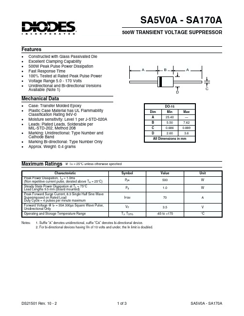
SA5V0A - SA170A
DO-15 Dim A B C D Min 25.40 5.50 0.686 2.60 Max — 7.62 0.889 3.6
All Dimensions in mm
Maximum Ratings
@ TA = 25°C unless otherwise specified Symbol Ppk Pd IFSM VF TJ, TSTG Value 500 1.0 70 3.5 -65 to +175 Unit W W A V °C
1. Suffix “A” denotes unidirectional, suffix “CA” denotes bi-directional device. 2. For bi-directional devices having VR of 10 volts and under, the IR limit is doubled.
1. Suffix “A” denotes unidirectional, suffix “CA” denotes bi-directional device. 2. For bi-directional devices having VR of 10 volts and under, the IR limit is doubled.
A
B
A
D
C
Mechanical Data
基尔斯特 5155A 型号多通道充电放大器 使用手册说明书

Page 1/6Electronics & SoftwareMultichannel Amplifierfor the Injection Molding Industry5155A _000-403e -03.09©2009, Kistler Group, Eulachstrasse 22, 8408 Winterthur, Switzerland This information corresponds to the current state of knowledge. Kistler reserves the right to make technical changes. Liability for consequential damage resulting Type 5155A...The purpose of the multichannel charge amplifier Type 5155A… with 1, 2 or 4 channels is to convert the charge signal from piezoelectric sensors or the signal from thermocouples into a proportional voltage signal. This amplifier has beend eveloped for industrial applications, primarily for injection molding machines.• Charge amplifier with 2 measuring ranges • Charge and thermocouple amplifier• Self-optimizing switch-over output (SmartAmp-Option)• Industrial case with IP65 protectionDescriptionThe multichannel charge amplifier Type 5155A... is provided with one, two or four charge amplifier modules (indicated in the circuit diagram as MLV). The two measuring ranges of the charge amplifier inputs can be switched over for each chan-nel individually by remote control. Amplifiers equipped with temperature inputs are provided with 1 charge amplifier and 1 temperature amplifier or 2 charge amplifiers and 2 tem-perature amplifiers. All charge amplifier modules contain at the input a capacitive negative feedback amplifier in hybrid design with an extremely high insulation resistance.In thermoplastic injection molding, the SmartAmp option "self-optimizing switch-over detection" automatically d etects volumetric filling of the mold, and in each cycle sends a con-trol signal to the injection molding machine. The mold must be equipped with a directly measuring cavity pressure sensor close to the gate.ApplicationThe multichannel charge amplifier Type 5155A… is intended for use with all types of piezoelectric sensors and Type K ther-mocouples. The output signals can be used to monitor, control and optimize the injection molding process.The SmartAmp option "self-optimizing switch-over detec-tion" can be e asily integrated in machine control systems. Forr etrofitting, the injection molding machine must be prepared by the m achine manufacturer. This option considerably reduce the setting-up time, since the switching point is automatically preset by means of the charge amplifier without the need of manual optimization. D uring production, the option auto-matically compensate process fluctuations, thereby producing moldings of greater uniformity.Photo of version with2-channel charge amplifier (TNC) +2-channel thermocouple amplifierPage 2/65155A _000-403e -03.09©2009, Kistler Group, Eulachstrasse 22, 8408 Winterthur, SwitzerlandTel.+41522241111,Fax+41522241414,****************, This information corresponds to the current state of knowledge. Kistler reserves the right to make technical changes. Liability for consequential damage resulting Technical DataCharge Amplifier Number of channels1, 2 or 4Measuring range I pC min. ±5 000pC max. ±50 000adjusted toType 5155A1xxx pC ±50 000 Type 5155A2xxx pC ±20 000Type 5155A3xxx pC customer optionMeasuring range ratios Range I/Range II Type 5155Ax1xx 10 Type 5155Ax2xx 4 Type 5155Ax3xx2DriftpC/s <±0,05Reset-Operate transient pC <±2Maximum voltage between V<±4sensor GND and output/ supply GNDInterference signal rejection dB >50between sensor GND and output/supply GND (0 ... 0,3 kHz) Maximum input signal:Voltage (continuous) V ±10 ChargepC ±150 000Voltage Output Error % <1Zero point error (Reset) mV <±10Output voltage V 0 ... ±10Output voltage limitation V >11Output current mA 0 ... ±5Output impedance Ω 10Output interference signal mV pp <10(0,1 Hz ... 1 MHz) Frequency response Deviation (−5 %) kHz ≈0 ... >3,5 Deviation (−3 dB) kHz ≈0 ... >10Current Output 4 ... 20 mAOption in place of voltage output. Not available for combined charge amplifier and thermocouple amplifier versions.Error % <1,3Zero point error (Reset) mA <±0,016Output current mA 4 ... 20Output current limitation mA 25Output impedance MΩ >40Maximum load resistance Ω 650Thermocouple AmplifierNoise suppression (ground loop) through differential input stage Number of channels 1 or 2Thermocouple (switchable to Type K Type J available on request) Measuring range °C 0 ... 200Output voltage V 0 ... 10Output current mA 0 ... 2Input impedance MΩ >1Output impedance Ω 10Zero point error mV <10Transmission sensitivity 1)mV/K 50Error (gain) % ±0,5Error (non-linearity) °C <1,5Output interference signal mV pp <20 (0,1 Hz ... 1 MHz) Frequency range kHz 0 ... >1Max. voltage between input V <±4 minus and output/supply GND Sensor disconnection detection V ≈-41)Calibration: 0 °C = 0 V, 100 °C = 5 V A differential input circuit ensures that common-mode signals of ±4 V between Sensor/Low and Output/Power GND, such as occur in in-dustrial environments, have no disturbing influence.Control inputs for Reset/Operate, Measuring Range II, Sensitivity,TestActuation is bipolar and electrically isolated via optocouplers. The common input of Test/Operate/Measuring range II/Sensitivity (Con-trol GND, PIN 18 of the D-Sub connector) can be connected internally either with the potential Exct 18 ... 30 VDC or Exct GND. Accordingly Test, Operate, Measuring range II and Sensitivity are actuated with negative voltage or optionally with user specified voltage.Actuation voltage Operate (logic 1) V 3 (30)Reset (logic 0)V <2 Measuring range II (logic 1) V 3 (30)Measuring range I (logic 0) V <2 Test signal (logic 1) V 3 (30)No Test signal (logic 0)V <2 Sensitivity <5 pC/bar (logic 1) V 3 (30)Sensitivity >5 pC/bar (logic 0) V <2Actuation currentmA0,6 (9)Output signal when Test and Measuring range II active Voltage outputV 8 Current output 4 ... 20 mA mA 16,8Tolerance of test signal% 5Page 3/65155A _000-403e -03.09©2009, Kistler Group, Eulachstrasse 22, 8408 Winterthur, SwitzerlandTel.+41522241111,Fax+41522241414,****************, This information corresponds to the current state of knowledge. Kistler reserves the right to make technical changes. Liability for consequential damage resulting FIX/SLThe outputs are switched via photo MOS relays.Current rating, continuous mA <100Current rating, pulse (<0,1 s) mA <300Resistance when switched onΩ <50 typical Ω 30Constant voltage V <±42Voltage between outputs and protective ground V RMS <30Power Supply Supply voltage VDC 18 (30)Current consumption per Charge amplifier channel mA ≈10 (without load and without SLP) Thermocouple channel mA ≈15(without load)Additional current consumption by SLP mA ≈35 Current output per channel mA ≈2,5(without load) Connections SensorCharge input Type TNC neg. or BNC neg. or 4-channel Fischermultipole plugThermocouple input Type FischerDBPU 102 A051female Supply, signal outputs,D-Sub Control inputsType25 pin maleGeneral DataOperating temperature range °C 0 ... 60Min./max. temperature °C −10/70Vibration resistancegp 10(20 ... 2 000 Hz, duration 16 min., cycle 2 min.)Shock resistance (1 ms)g 200Degree of protection (only with scre- IP 65 wed-on TNC connectors) DIN 40050 Housing material die castaluminiumWeightg≈400• Recommended mounting position: on perpendicular sur-face, connections downward• The case ground is connected to the output or supply ground only via an R/C network. This prevents interference due to a "floating" case.Contact Assignment D-Sub 25 Connector7 Exct 18 ... 30 VDC 8 Exct GND 9 NC 10 NC11 Common FIX/SL 12 FIX c)13 SL c)14 Signal GND 15 NC 16 NC 17 NC18 Common Control 19 Operate 20 Sensitivity c)21 Test22 Range II Ch123 Range II Ch2 a) d)24 Range II Ch3 b) d)25 Range II Ch4 b) d)a) with 1 channel version: NCb) with 1 and 2 channel version: NCc) with version without SmartAmp "self-optimizing switching-point detection": NCd) with temperature input: NCPage 4/6©2009, Kistler Group, Eulachstrasse 22, 8408 Winterthur, SwitzerlandTel.+41522241111,Fax+41522241414,****************, This information corresponds to the current state of knowledge. Kistler reserves the right to make technical changes. Liability for consequential damage resulting Block Schematic DiagramPage 5/65155A _000-403e -03.09©2009, Kistler Group, Eulachstrasse 22, 8408 Winterthur, SwitzerlandTel.+41522241111,Fax+41522241414,****************, This information corresponds to the current state of knowledge. Kistler reserves the right to make technical changes. Liability for consequential damage resultingPage 6/65155A _000-403e -03.09©2009, Kistler Group, Eulachstrasse 22, 8408 Winterthur, SwitzerlandTel.+41522241111,Fax+41522241414,****************, This information corresponds to the current state of knowledge. Kistler reserves the right to make technical changes. Liability for consequential damage resulting Optional AccessoriesArt. No./Type • 2 cheese-head screws M4 x 16 6.120.013• 2 spring washers M4 6.230.063• TNC-BNC adapter1709• Connecting cable (with open end) for con- 1200A73nection to the injection molding machineOptional AccessoriesArt. No./Type • D-Sub plastic cover, water-tight,1557A10shielded and 25 pin D-Sub connector (CONEC 165 X 15039X)• Connecting cable (equalizing cable) for the connection of temperature sensors Length = 2 m 2295A2 Length = 5 m2295A5Ordering KeyMeasuring Range I (Calibrated)±50 000 pC 1±20 000 pC2According to order3Ratio Measuring Range I/Measuring Range II 10 14 223Channels, Sensor Connection1 channel charge, TNC neg. (IP65) 11 channel charge, BNC neg. (IP60) 22 channel charge, TNC neg. (IP65) 32 channel charge, BNC neg. (IP60) 44 channel charge, TNC neg. (IP65) 74 channel charge, BNC neg. (IP60)84 channel charge, 4 channel connector for cable type 1995A... 5****1 channel charge, TNC neg., 1 channel temperature (IP65) A***1 channel charge, BNC neg., 1 channel temperature (IP60) B***2 channel charge, TNC neg., 2 channel temperature (IP65) C***2 channel charge, BNC neg., 2 channel temperature (IP60) D***SmartAmpSmartAmp without SmartAmp, voltage output 1without SmartAmp, current output2*with SmartAmp "self-optimizing switching-point detection", voltage output 3**with SmartAmp "self-optimizing switching-point detection", current output4*** Not possible in combination with thermocouple amplifier ** Charge amplifiers are supplied only with Range I = 20000 pC and ratio Range I/Range II = 4*** Charge and thermocouple amplifier only available with Range I = 20000 pCand ratio Range I/Range II = 4**** Charge amplifiers are supplied only with Range I = 20000 pCand ratio Range I/Range II = 4; without SmartAmp; current output not available。
DTSD51(DSSD51) E×型三相电子式多功能电能表说明书
代表:无此项功能;
代表:此项功能可选 )
DSSD51/DTSD51 E×型三相电子式多功能电能表
说 明 书
3
1.3 技术指标 准确度等级 有功 0.5S 0.5 1.0 无功 2.0 参比电压 3×220/380V 3×57.7/100V (三相四线) 3×100V(三相三线) 额定电流 3×0.5(2)A、3×1(2)A 、3×1.5(6)A、3×3(6)A 、3×5(20)A、 3×10(40)A、3×15(60)A、3×20(80)A、3×30(100)A 额定频率 50Hz 起动电流 有功 0.001In(0.5S ,0.5) 0.002In(1.0) 无功 0.003In (2.0) 潜动 具有防潜动逻辑设计 外型尺寸 278mm164mm78mm(普通端盖)、328mm164mm78mm(大端盖) 重量 约 1.9kg 电气参数 正常工作电压 极限工作电压 电压线路功耗 电流线路功耗 数据备份电池电压 停电抄表电池电压 费率工作参数 时钟准确度(日误差) 电池容量 停电后数据保存时间 气候条件 正常工作温度 极限工作温度 存储和运输温度 存储和工作湿度 技术参数 费率数 时段数 计度范围 显 示 通讯波特率 通讯规约 4 10 0~999999.99kWh,0~999999.99kvarh 液晶 RS485 口:1200bps~9600 bps 可设置 《DL/T645-1997 多功能电能表通信规约》 -20℃~+45℃ -30℃~+60℃ -40℃~+70℃ ≤85% ≤0.5S (23℃) ≥1000mAh ≥10 年(用新电池) 0.9Un~1.1Un 0.75Un~1.2Un ≤2W 和 5VA ≤2.5VA 3.6VDC 2×3.0VDC (电池型号 CR123A)
15KE16CA中文资料

1.5KE6V8(C)A - 1.5KE400(C)A
1500W TRANSIENT VOLTAGE SUPPRESSOR Features
· · · · · · 1500W Peak Pulse Power Dissipation Voltage Range 6.8V - 400V Constructed with Glass Passivated Die Uni- and Bidirectional Versions Available Excellent Clamping Capability Fast Response Time
VRWM, REVERSE STANDOFF VOLTAGE (V) Fig. 2 Typical Total Capacitance
1 of 3
1.5KE6V8(C)A - 1.5KE400(C)A
元器件交易网
Type Number (Note 1) (UNI) Type Number (Note 1) (BI) VRWM (V) 5.80 6.40 7.02 7.78 8.55 9.40 10.20 11.10 12.80 13.60 15.30 17.10 18.80 20.50 23.10 25.60 28.20 30.80 33.30 36.80 40.20 43.60 47.80 53.00 58.10 64.10 70.10 77.80 85.50 94.00 102.00 111.00 128.00 136.00 145.00 154.00 171.00 185.00 214.00 256.00 300.00 342.00 Min (V) 6.45 7.13 7.79 8.65 9.50 10.50 11.40 12.40 14.30 15.20 17.10 19.00 20.90 22.80 25.70 28.50 31.40 34.20 37.10 40.90 44.70 48.50 53.20 58.90 64.60 71.30 77.90 86.50 95.00 105.00 114.00 124.00 143.00 152.00 162.00 171.00 190.00 209.00 237.00 285.00 332.00 380.00 Max (V) 7.14 7.88 8.61 9.55 10.50 11.60 12.60 13.70 15.80 16.80 18.90 21.00 23.10 25.20 28.40 31.50 34.70 37.80 41.00 45.20 49.40 53.60 58.80 65.10 71.40 78.80 86.10 95.50 105.00 116.00 126.00 137.00 158.00 168.00 179.00 189.00 210.00 231.00 263.00 315.00 368.00 420.00 It (mA) 10 10 10 1.0 1.0 1.0 1.0 1.0 1.0 1.0 1.0 1.0 1.0 1.0 1.0 1.0 1.0 1.0 1.0 1.0 1.0 1.0 1.0 1.0 1.0 1.0 1.0 1.0 1.0 1.0 1.0 1.0 1.0 1.0 1.0 1.0 1.0 1.0 1.0 1.0 1.0 1.0 Reverse Standoff Voltage Breakdown Voltage VBR @ IT Max. Reverse Leakage (Note 2) @ VR IR (mA) 1000 500 200 50 10 5.0 5.0 5.0 5.0 5.0 5.0 5.0 5.0 5.0 5.0 5.0 5.0 5.0 5.0 5.0 5.0 5.0 5.0 5.0 5.0 5.0 5.0 5.0 5.0 5.0 5.0 5.0 5.0 5.0 5.0 5.0 5.0 5.0 5.0 5.0 5.0 5.0 Max. Clamping Voltage @ Ipp VC (V) 10.5 11.3 12.1 13.4 14.5 15.6 16.7 18.2 21.2 22.5 25.2 27.7 30.6 33.2 37.5 41.4 45.7 49.9 53.9 59.3 64.8 70.1 77.0 85.0 92.0 103.0 113.0 125.0 137.0 152.0 165.0 179.0 207.0 219.0 234.0 246.0 274.0 328.0 344.0 414.0 482.0 548.0 Max. Peak Pulse Current IPP (A) 143.0 132.0 124.0 112.0 103.0 96.0 90.0 82.0 71.0 67.0 59.5 54.0 49.0 45.0 40.0 36.0 33.0 30.0 28.0 25.3 23.2 21.4 19.5 17.7 16.3 14.6 13.3 12.0 11.0 9.9 9.1 8.4 7.2 6.8 6.4 6.1 5.5 4.6 5.0 5.0 4.0 4.0 Max. Voltage Temp. Variation of VBR %/°C 0.057 0.061 0.065 0.068 0.073 0.075 0.078 0.081 0.084 0.086 0.088 0.090 0.092 0.094 0.096 0.097 0.098 0.099 0.100 0.101 0.101 0.102 0.103 0.104 0.104 0.105 0.105 0.106 0.106 0.107 0.107 0.107 0.108 0.108 0.108 0.108 0.108 0.108 0.110 0.110 0.110 0.110
LC245A中文资料
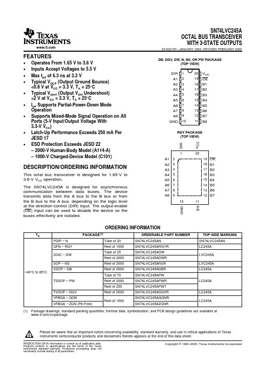
GQN OR ZQN PACKAGE (TOP VIEW)
1234
A B C D E
TERMINAL ASSIGNMENTS
1
2
3
4
A
A1
DIR
VCC
OE
B
A3
B2
A2
B1
C
A5
A4
B4
B3
D
A7
B6
A6
B5
E
GND
A8
B8
B7
FUNCTION TABLE
INPUTS
OE DIR
L
L
L
H
H
X
OPERATION
QFN – RGY
Reel of 1000
SN74LVC245ARGYR
SOIC – DW
Tube of 25 Reel of 2000
SN74LVC245ADW SN74LVC245ADWR
SOP – NS
Reel of 2000
SN74LVC245ANSR
SSOP – DB
Reel of 2000
Please be aware that an important notice concerning availability, standard warranty, and use in critical applications of Texas Instruments semiconductor products and disclaimers thereto appears at the end of this data sheet.
DIR 1 A1 2 A2 3 A3 4 A4 5 A5 6 A6 7 A7 8 A8 9 GND 10
CTA141AQ12VDCD资料

Distributor: Electro-Stock Tel: 630-682-1542 Fax: 630-682-1562FEATURES:• Large switching capacity up to 80A• Ideal for high inrush applications• quick connect mounting available• Suitable for automobile and lamp accessories• QS-9000, ISO-9002 Certified Manufacturing32.6 x 34.6 x 34.0 mmCONTACT DATAContact Arrangement 1A = SPST N.O.1C = SPDTContact Rating 1A: 100A @ 12VDC; 50A @ 24VDC1C: N.O. 100A @ 12VDC; 50A @ 24VDCN.C. 70A @ 12VDC; 35A @ 24VDCContact Resistance < 30 milliohms initialContact Material AgSnO2Maximum Switching Power 1200WMaximum Switching Voltage 75VDCMaximum Switching Current 100ACOIL DATACoil VoltageVDCRated Max. Coil ResistanceΩ± 10%Pick Up VoltageVDC (max)75%of rated voltageRelease VoltageVDC (min)10%of rated voltageCoil PowerWOperate TimemsRelease Timems12 15.6 50 8.4 1.2 24 31.2 195 16.8 2.4 2.9 105 CAUTION:1. The use of any coil voltage less than the rated coil voltage may compromise the operation of the relay.2. Pickup and release voltages are for test purposes only and are not to be used as design criteria.GENERAL DATAElectrical Life @ rated load Mechanical Life 100K cycles, typical 10M cycles, typicalInsulation Resistance 100MΩ min @ 500VDCDielectric Strength, Coil to Contact Contact to Contact 2500V rms min. @ sea level 1500V rms min. @ sea levelShock Resistance 147m/s2 for 11msVibration Resistance 1.5mm double amplitude 10-40Hz Terminal (Copper Alloy) Strength 30NOperating Temperature Storage Temperature -40 °C to + 85 °C -40 °C to + 155 °CSolderability 230 °C ± 2 °C for 10 ± 0.5sWeight 60gCTA14Distributor: Electro-Stock Tel: 630-682-1542 Fax: 630-682-1562ORDERING INFORMATION1. Series:12VDC CTA14CTA14 2.Contact Arrangement: 1A = SPST N.O. 1C = SPDT1C3. Sealing Options: C = Dust CoverC 4. Termination Options: Q = Quick Connect Q 5. Coil Voltage: 12VDC 24VDC6: Coil Suppression: Blank = Standard D = Diode (1N4005)R = Resistor (680 Ohms) 2D = 2 diodes (1N4005)DR = Diode & Resistor (1N4005 & 680 Ohms) ** Consult factory if other values are needed.DIMENSIONSSCHEMATICS (BOTTOM VIEWS)1A 1CCTA14。
DPA51系列三相电源监视器说明书

DPA51系列三相电源监视器说明书一、概述DPA51系列三相电源监视器为三相或三相四线制供电的电源监视器。
本系列产品测量自身供电电压、再生电压,具有相序保护、缺相保护、三相电压不平衡保护等功能,N型产品附带有零线断线保护功能。
DPA51系列监视器为超薄(17.5mm)导轨安装型,适用于柜内安装的配电系统保护,如:配电柜、配电箱、电控箱、机床等设备。
具有超高的性价比。
二、输入额定电压(测量范围):200~480V AC±15% (线电压)型号: DPA51CM44\DPA51CM44H500~690V AC±15% (线电压)型号: DPA51CM69115~277V AC±15% (相电压)型号: DPA51AM44N288~398V AC±15% (相电压)型号: DPA51AM69N三、功能选型四、技术参数产品认证产品标准 GB14048.1-2000、GB14048.5-2008ISO IEC60947-5-1:2003CE标志L. V. Directive 2006/95/EC EMC Directive 2004/108/ECROHS指令 2011/65/EU CCC A037133工作状态指示电源供应绿色LED各相及相序正常黄色LED故障保护黄色LED 灭零线断线保护绿色/黄色LED 灭输出回路触点数量 SPDT\SPNO 动作原则闭路原则触点材料 AgSnO额定电压24VDC,250V AC额定开关电流 DC12 24V 5A AC15 250V 2.5A DC13 24V 2.5A机械寿命≥ 107次电气寿命≥ 105次(at 5 A, 250 V, cos ψ = 1)其他数据外形尺寸17.5x 81x 67.2 mm材料 PA66或PC导线载面面职1×2.5mm2(AWG13)安装位置任何防护等级 IP20 污染等级Ш级工作温度@最高电压、50Hz-20…+60℃,R.H. < 95%储存温度 -30…+80℃,R.H. < 95%安装 DIN导轨(DIN 43880)绝缘强度绝缘电压≥ 2kV AC (rms)额定承受脉冲电压 4 kV (1.2/50 µs)五、保护原理相序监测:当三相电源监视器通电时,如相序正常时,继电器才能吸合。
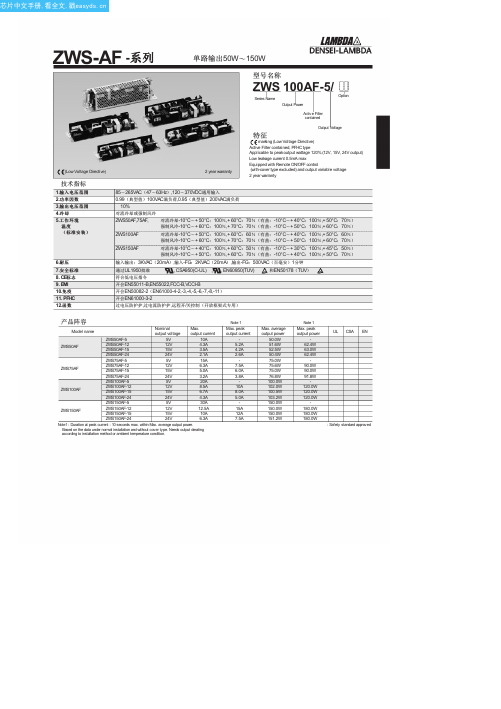
ZWS150PAF-24JA中文资料(DENSEI-LAMBDA)中文数据手册「EasyDatasheet - 矽搜」
推荐线束
P134 P209
(Unit: mm)
(Unit: mm)
(Unit: mm)
推荐噪声滤波器
MAW-1203-22 GO!!
推荐线束
P134 P209
(Unit: mm)
Nominal output voltage
3.3V 5V 12V 15V 24V
36V 48V 3.3V 5V 12V 15V
24V 36V 48V 24V 36V 3.3V
5V 12V 15V 24V 36V 48V
Max. output current
15A 15A 6.3A 5A 3.2A
2.1A 1.6A 20A 20A 8.5A 6.7A
芯片中文手册,看全文,戳
ZWS-PF -系列
ZWS75PF (STD型号:MOLEX连接器) ZWS75PF (/ J型:JST连接器) ZWS75PF (/ JA类型:有盖型JST连接器)
ZWS100PF (STD型号:MOLEX连接器)
推荐噪声滤波器
MAW-1203-22 GO!!
120.0W 120.0W 120.0W
180.0W 180.0W 180.0W
UL CSA EN : Safety standard approved
芯片中文手册,看全文,戳
ZWS-AF -系列
ZWS50AF (STD型号:MOLEX连接器,/ J型:JST连接器)
ZWS50AF (/ JA类型:有盖型)
开会EN61000-3-2
ZWS75PF,ZWS100PF(输入功率:50W以上) ZWS120PPF,ZWS150PF(输入功率:over75W)
过电压防护护,过电流防护护
- 1、下载文档前请自行甄别文档内容的完整性,平台不提供额外的编辑、内容补充、找答案等附加服务。
- 2、"仅部分预览"的文档,不可在线预览部分如存在完整性等问题,可反馈申请退款(可完整预览的文档不适用该条件!)。
- 3、如文档侵犯您的权益,请联系客服反馈,我们会尽快为您处理(人工客服工作时间:9:00-18:30)。
GENERAL DATA
Electrical Life @ rated load Mechanical Life Insulation Resistance Dielectric Strength, Coil to Contact Contact to Contact Shock Resistance Vibration Resistance Terminal (Copper Alloy) Strength Operating Temperature Storage Temperature Solderability Weight 100K cycles, typical 10M cycles, typical 100MΩ min @ 500VDC 750V rms min. @ sea level 500V rms min. @ sea level 200m/s2 for 11ms 1.27mm double amplitude 10-40Hz 10N -40 °C to + 85 °C -40 °C to + 155 °C 230 °C ± 2 °C for 10 ± 0.5s 19g open. 21g covered
Hale Waihona Puke 24.0x19.0x20.0mm
CONTACT DATA
Contact Arrangement Contact Rating Contact Resistance Contact Material Maximum Switching Power Maximum Switching Voltage Maximum Switching Current 1A = SPST N.O. 1B = SPST N.C. 1C = SPDT 1A: 40A @ 14VDC 1B: 30A @ 14VDC, 20A @ 120VAC, 15A @ 28VDC 1C: 30A @ 14VDC, 20A @ 120VAC, 15A @ 28VDC < 50 milliohms initial AgCdO 360W 75VDC, 380VAC 40A
CTA5
CTA5 1A C 40 12VDC 1.6 S
ORDERING INFORMATION
DIMENSIONS: (Units = mm)
PCB Layout
Standard
European
Schematic
CIT RELAY Website:
Tel: 763-535-2339
CIT RELAY Website:
Tel: 763-535-2339
Fax: 763-535-2194
元器件交易网
CIT RELAY™
1. Series: CTA5 2.Contact Arrangement: 1A = SPST N.O. 1B = SPST N.C. 1C = SPDT 3. Sealing Options: O = Open Frame S = Sealed C = Dust Cover 4. Contact Ratings: 15 = 15A 30 = 30A 40 = 40A 5. Coil Voltage: 6VDC 9VDC 12VDC 18VDC 24VDC 6. Coil Power: 1.6 = 1.6W 1.9 = 1.9W 7. PCB Layout: S = Standard E = European
元器件交易网
CIT RELAY™
CTA5
FEATURES: • Switching capacity up to 40A @ 14VDC • Small size and light weight • PCB pin mounting available • Suitable for automobile and lamp accessories • Two footprint styles available
COIL DATA
Coil Voltage VDC Coil Resistance Ω ± 10% Pick Up Voltage VDC (max) 75% of rated voltage Release Voltage VDC (min) 10% of rated voltage Coil Power W Operate Time ms Release Time ms
Fax: 763-535-2194
5
3
CAUTION: 1. The use of any coil voltage less than the rated coil voltage may compromise the operation of the relay. 2. Pickup and release voltages are for test purposes only and are not to be used as design criteria.
Rated
Max.
6 9 12 18 24
7.8 11.7 15.6 23.4 31.2
1.6W 22.5 50.6 90.0 202.5 360.0
1.9W 19.0 42.6 75.8 170.5 303.2
4.2 6.3 8.4 12.6 16.8
0.6 0.9 1.2 1.8 2.4
1.6 or 1.9