WM011I WH,WM011I,AL,WM011I,GY,WM011I,BK, 规格书,Datasheet 资料
SLM-140;SLM-150;SLM-160;SLM-170;SLM-180;中文规格书,Datasheet资料

H .815 (20.7mm) .835 (21.2mm) .855 (21.7mm) .875 (22.2mm) .895 (22.7mm) .915 (23.2mm) .935 (23.7mm) .955 (24.3mm) .975 (24.8mm) .995 (25.3mm) 1.015 (25.8mm) 1.035 (26.3mm)
CHECKED:
04/23/03
DATE:
SLM-XXX
D
CAGE CODE : 32559
SHEET # 1 OF 1
D. Green
04/23/03
CAD GENERATED DOCUMENT, DO NOT MEASURE DRAWING., CA. 92618
M. C. M. C. M. C.
0.100 [2.5mm] Ø.250 [Ø6.4mm] Ø.290 [Ø7.4mm]
H 0.15 [3.8mm] SH REF. Ø.230 [Ø5.8mm] Ø.045 [Ø1.1mm] TYP. CATHODE I.D. MARKING 0.025 [0.6mm]
H .425 (10.8mm) .435 (11.0mm) .445 (11.3mm) .455 (11.6mm) .465 (11.8mm) .475 (12.1mm) .485 (12.3mm) .495 (12.6mm) .505 (12.8mm) .515 (13.1mm) .525 (13.3mm) .535 (13.6mm) .545 (13.8mm) .555 (14.1mm)
PART NO. SLM-420 SLM-430 SLM-440 SLM-450 SLM-470 SLM-490 SLM-510 SLM-530 SLM-550 SLM-570 SLM-590 SLM-610 SLM-630 SLM-650
0190250010;中文规格书,Datasheet资料
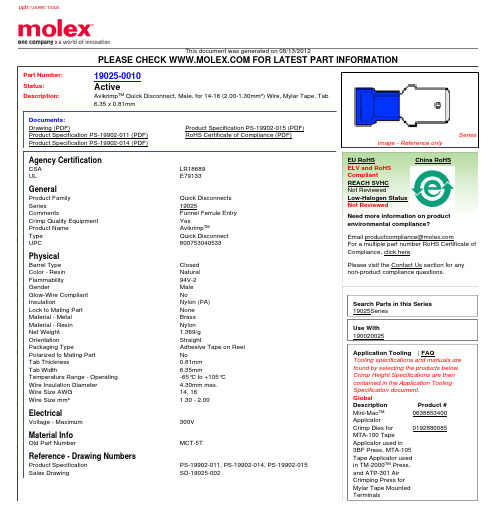
This document was generated on 08/13/2012PLEASE CHECK FOR LATEST PART INFORMATIONPart Number:19025-0010Status:ActiveDescription:Avikrimp™ Quick Disconnect, Male, for 14-16 (2.00-1.30mm²) Wire, Mylar Tape, Tab 6.35 x 0.81mmDocuments:Drawing (PDF)Product Specification PS-19902-015 (PDF)Product Specification PS-19902-011 (PDF)RoHS Certificate of Compliance (PDF)Product Specification PS-19902-014 (PDF)Agency CertificationCSA LR18689ULE79133GeneralProduct Family Quick Disconnects Series19025CommentsFunnel Ferrule Entry Crimp Quality Equipment YesProduct Name Avikrimp™Type Quick Disconnect UPC800753040533PhysicalBarrel Type Closed Color - Resin Natural Flammability 94V-2GenderMale Glow-Wire Compliant NoInsulationNylon (PA)Lock to Mating Part None Material - Metal Brass Material - Resin Nylon Net Weight 1.369/g OrientationStraightPackaging TypeAdhesive Tape on Reel Polarized to Mating Part NoTab Thickness 0.81mm Tab Width6.35mmTemperature Range - Operating -65°C to +105°C Wire Insulation Diameter 4.30mm max.Wire Size AWG 14, 16Wire Size mm²1.30 -2.00ElectricalVoltage - Maximum300V Material InfoOld Part NumberMCT-5TReference - Drawing NumbersProduct Specification PS-19902-011, PS-19902-014, PS-19902-015Sales DrawingSD-19025-002Seriesimage - Reference onlyEU RoHSChina RoHSELV and RoHS Compliant REACH SVHC Not ReviewedLow-Halogen Status Not ReviewedNeed more information on product environmental compliance?Email productcompliance@For a multiple part number RoHS Certificate of Compliance, click herePlease visit the Contact Us section for any non-product compliance questions.Search Parts in this Series 19025Series Use With 190020025Application Tooling | FAQTooling specifications and manuals are found by selecting the products below.Crimp Height Specifications are then contained in the Application Tooling Specification document.GlobalDescription Product #Mini-Mac™Applicator 0638853400Crimp Dies for MTA-100 Tape Applicator used in 3BF Press, MTA-105Tape Applicator used in TM-2000™ Press,and ATP-301 Air Crimping Press for Mylar Tape Mounted Terminals0192880085This document was generated on 08/13/2012PLEASE CHECK FOR LATEST PART INFORMATION分销商库存信息: MOLEX 0190250010。
E2K-L26MC1;E2K-L13MC1;中文规格书,Datasheet资料

Applicable to a Wide Range of Pipe Diameters.Capacitive Sensors unaffected by liquid color.•Mount to bypass pipes.•Fit a wide range of pipe diameters: 8 to 11 mm or 12 to 26mm •Built-in Amplifiers to save space.Be sure to read Safety Precautionsonpage 3.Ordering InformationSensing methodApplicable pipe diametersAppearanceOutput configuration/Operation modeModelCapacitive 8 to 11 mm NPN open-collector output NOE2K-L13MC1 2M12 to 26 mm E2K-L26MC1 2ME2K-LRatings and Specifications*Stable detection will not be possible in the following cases. Confirm detection capability with the Sensor installed before actual application.1. If the specific inductive capacity or the specific electric conductivity of the liquid is too low, the liquid position may not be detected since this sensor is a capacitive sensor.2. If the quantity of liquid is too low or the change in quantity is too low in comparison to the change in liquid level because the pipe is too thin or the walls of the pipe are too thick3. If there is a viscous film on the inner pipe wall, large quantities of foam or air bubbles, or excessive buildup of dirt on the inner pipe wallEngineering Data (Typical)ItemModelE2K-L13MC1E2K-L26MC1Applicable pipesMaterialsNon-metal SizeDiame-ter 8 to 11 mm 12 to 26 mm Thick-ness 1 mm max. 1.5 mm max.Detectable object Liquid *Repeat accuracy±0.2 mm max.Differential travel(Reference value, varies with pipe size and liquid.)0.6 to 5 mm 0.3 to 3 mm Power supply voltage (operating voltage range)12 to 24 VDC (10.8 to 30 VDC), ripple (p-p): 10% max.Current consumption 12 mA max.Control outputLoad current100 mA max.Residual voltage 1 V max. (Load current: 100 mA, Cable length: 2 m)Sensing liquid position Indented mark position (For details, refer to Technical Guide (Operational version).)IndicatorsDetection indicator (orange)Ambient temperature range Operating: 0 to 55°C (with no icing or condensation), Storage: −10 to 65°C (with no icing or condensation)Ambient humidity range Operating/Storage: 25% to 85% (with no condensation)Temperature influence ±4 mm of detection level at 23°C in the temperature range of 0 to 55°C (with pure water or 20% saline solution)(±6 mm for E2K-L13MC1 with pure water and a pipe diameter of 8 mm)Voltage influence ±0.5 mm of detection level at the rated voltage in rated voltage ±10% range Insulation resistance 50 M Ω min. (at 500 VDC) between current-carrying parts and case Dielectric strength 500 VAC, 50/60 Hz for 1 min between current-carrying parts and caseVibration resistance Destruction: 10 to 55 Hz, 1.5-mm double amplitude for 2 hours each in X, Y, and Z directions Shock resistance Destruction: 500 m/s 2 3 times each in X, Y, and Z directions Degree of protection IP66 (IEC)Connection method Pre-wired Models (Standard cable length: 2 m)Weight (packed state)Approx. 70 g Materials Case, Cover Heat-resistant ABS Cable clampNBRAccessoriesTwo bands, Four slip-proof tubes, Instruction manualInfluence of Temperature and Sensing Liquid Level E2K-L13MC1E2K-L26MC1−−−C h a n g e i n s e n s i n g l i q u i d l e v e l (m m )−−−C h a n g e i n s e n s i n g l i q u i d l e v e l (m m )ratings.● DesignInfluence of Surrounding ObjectsWhen mounting the Sensor, maintain at least the distances in the following diagrams from surrounding metal objects or otherconductors to prevent the Sensor from being affected by objects other than the sensing object.Influence of Surrounding Objects(Unit: mm)Mutual InterferenceWhen installing Sensors in series, in parallel, or face-to-face, ensure that the minimum distances given in the following table are maintained.Sensor may affect the detection level of the top Sensor.● Mounting MountingMount the Sensor securely to the pipe using the enclosed two bands and four slip-proof tubes (two tubes used for each band) as shown in the following diagram.When mounting the Sensor, be sure the entire Sensor is tight against the pipe along the sensing surface.ModelDistanceA B C E2K-L13MC125545E2K-L26MC140On One Side Liquid levelSet position mark)PipeSlip-proof tubesBandsSide ViewFront ViewTop ViewE2K-L● WiringPower Supply•If the load and Sensor are connected to different power supplies, always turn ON the Sensor power first.•Switching noise can cause operating mistakes if a commercial switching regulator is used. When using a switching regulator, always ground the frame ground terminal and the ground terminal. ● Operating EnvironmentAmbient Atmosphere•Although the Sensor is water resistance, it is a capacitive sensor and should not be used where it will come into direct contact with liquids, such as water or cutting oil.•The life of the Sensor will be shorten by rapid changes in temperature even within the ambient operating temperature range. Do not use the Sensor in locations subject to rapid temperature changes.● MiscellaneousDrift will occur when the power supply is turned ON. If the specific inductive capacity of the sensing liquid is low, the detection level may increase by 2 to 3 mm during the 20 minutes required from the time the power supply is turned ON until operation stabilizes.Dimensions (Unit: mm)Tolerance class IT16 applies to dimensions in this data sheet unless otherwise specified.E2K-L13MC1E2K-L26MC1Read and Understand This CatalogPlease read and understand this catalog before purchasing the products. Please consult your OMRON representative if you have any questions orcomments.WARRANTYOMRON's exclusive warranty is that the products are free from defects in materials and workmanship for a period of one year (or other period if specified) from date of sale by OMRON.OMRON MAKES NO WARRANTY OR REPRESENTATION, EXPRESS OR IMPLIED, REGARDING NON-INFRINGEMENT, MERCHANTABILITY, OR FITNESS FOR PARTICULAR PURPOSE OF THE PRODUCTS. ANY BUYER OR USER ACKNOWLEDGES THAT THE BUYER OR USER ALONE HAS DETERMINED THAT THE PRODUCTS WILL SUITABLY MEET THE REQUIREMENTS OF THEIR INTENDED USE. OMRON DISCLAIMS ALL OTHER WARRANTIES, EXPRESS OR IMPLIED.LIMITATIONS OF LIABILITYOMRON SHALL NOT BE RESPONSIBLE FOR SPECIAL, INDIRECT, OR CONSEQUENTIAL DAMAGES, LOSS OF PROFITS OR COMMERCIAL LOSS IN ANY WAY CONNECTED WITH THE PRODUCTS, WHETHER SUCH CLAIM IS BASED ON CONTRACT, WARRANTY, NEGLIGENCE, OR STRICT LIABILITY.In no event shall the responsibility of OMRON for any act exceed the individual price of the product on which liability is asserted.IN NO EVENT SHALL OMRON BE RESPONSIBLE FOR WARRANTY, REPAIR, OR OTHER CLAIMS REGARDING THE PRODUCTS UNLESSOMRON'S ANALYSIS CONFIRMS THAT THE PRODUCTS WERE PROPERLY HANDLED, STORED, INSTALLED, AND MAINTAINED AND NOTSUBJECT TO CONTAMINATION, ABUSE, MISUSE, OR INAPPROPRIATE MODIFICATION OR REPAIR.SUITABILITY FOR USEOMRON shall not be responsible for conformity with any standards, codes, or regulations that apply to the combination of products in the customer's application or use of the products.At the customer's request, OMRON will provide applicable third party certification documents identifying ratings and limitations of use that apply to the products. This information by itself is not sufficient for a complete determination of the suitability of the products in combination with the end product, machine, system, or other application or use.The following are some examples of applications for which particular attention must be given. This is not intended to be an exhaustive list of all possible uses of the products, nor is it intended to imply that the uses listed may be suitable for the products:•Outdoor use, uses involving potential chemical contamination or electrical interference, or conditions or uses not described in this catalog.•Nuclear energy control systems, combustion systems, railroad systems, aviation systems, medical equipment, amusement machines, vehicles, safety equipment, and installations subject to separate industry or government regulations.•Systems, machines, and equipment that could present a risk to life or property.Please know and observe all prohibitions of use applicable to the products.NEVER USE THE PRODUCTS FOR AN APPLICATION INVOLVING SERIOUS RISK TO LIFE OR PROPERTY WITHOUT ENSURING THAT THE SYSTEM AS A WHOLE HAS BEEN DESIGNED TO ADDRESS THE RISKS, AND THAT THE OMRON PRODUCTS ARE PROPERLY RATED AND INSTALLED FOR THE INTENDED USE WITHIN THE OVERALL EQUIPMENT OR SYSTEM.PROGRAMMABLE PRODUCTSOMRON shall not be responsible for the user's programming of a programmable product, or any consequence thereof.CHANGE IN SPECIFICATIONSProduct specifications and accessories may be changed at any time based on improvements and other reasons.It is our practice to change model numbers when published ratings or features are changed, or when significant construction changes are made.However, some specifications of the products may be changed without any notice. When in doubt, special model numbers may be assigned to fix or establish key specifications for your application on your request. Please consult with your OMRON representative at any time to confirm actualspecifications of purchased products.DIMENSIONS AND WEIGHTSDimensions and weights are nominal and are not to be used for manufacturing purposes, even when tolerances are shown.PERFORMANCE DATAPerformance data given in this catalog is provided as a guide for the user in determining suitability and does not constitute a warranty. It may represent the result of OMRON’s test conditions, and the users must correlate it to actual application requirements. Actual performance is subject to the OMRON Warranty and Limitations of Liability.ERRORS AND OMISSIONSThe information in this document has been carefully checked and is believed to be accurate; however, no responsibility is assumed for clerical,typographical, or proofreading errors, or omissions.2008.11In the interest of product improvement, specifications are subject to change without notice. OMRON CorporationIndustrial Automation Company/(c)Copyright OMRON Corporation 2008 All Right Reserved.分销商库存信息:OMRONE2K-L26MC1E2K-L13MC1。
BLF6G21-10G,135;中文规格书,Datasheet资料

PL(AV) = 0.7 W
-
−50 -
dBc
Table 8. Application information Mode of operation: 1-carrier W-CDMA; PAR 7.5 dB at 0.01 % probability on CCDF; 3GPP test model 1; 1-64 PDPCH; f1 = 2112.5 MHz; f2 = 2167.5 MHz; RF performance at VDS = 28 V; IDq = 100 mA; Tcase = 25 °C; unless otherwise specified; in a class-AB production test circuit.
I Easy power control I Integrated ESD protection I Excellent ruggedness I High efficiency
/
NXP Semiconductors
BLF6G21-10G
Power LDMOS transistor
test model 1; 1-64 PDPCH; f1 = 2112.5 MHz; f2 = 2117.5 MHz; f3 = 2162.5 MHz; f4 = 2167.5 MHz; RF performance at VDS = 28 V; IDq = 100 mA; Tcase = 25 °C; unless otherwise specified; in a class-AB production test circuit.
Table 4. Limiting values In accordance with the Absolute Maximum Rating System (IEC 60134).
0190350003;中文规格书,Datasheet资料

This document was generated on 08/31/2012PLEASE CHECK FOR LATEST PART INFORMATIONPart Number:19035-0003Status:ActiveDescription:Avikrimp™ Snap Plug, for 18-22 AWG Wire, Box, 22.55mm LengthDocuments:Drawing (PDF)Product Specification PS-19902-013 (PDF)Product Specification PS-19902-011 (PDF)RoHS Certificate of Compliance (PDF)Agency CertificationCSA LR18689ULE152602GeneralProduct Family Quick Disconnects Series19035CommentsMolded Nylon Insulation Crimp Quality Equipment YesProduct Name Avikrimp™Type Snap PlugUPC800753047846PhysicalBarrel Type Closed Color - Resin Natural Flammability 94V-2GenderMale Glow-Wire Compliant NoInsulationNylon (PA)Lock to Mating Part None Material - Metal Copper Material - Resin Nylon Net Weight 1.346/g OrientationStraight Packaging Type Bag Tab Thickness N/A Tab WidthN/AWire Insulation Diameter 3.60mm max.Wire Size AWG 18, 20, 22Wire Size mm²0.35 - 0.80ElectricalVoltage - MaximumN/A Material InfoOld Part NumberA-569Reference - Drawing NumbersProduct Specification PS-19902-011, PS-19902-013Sales DrawingSD-19035-001Seriesimage - Reference onlyEU RoHSChina RoHSELV and RoHS Compliant REACH SVHCContains SVHC: No Low-Halogen Status Low-HalogenNeed more information on product environmental compliance?Email productcompliance@For a multiple part number RoHS Certificate of Compliance, click herePlease visit the Contact Us section for any non-product compliance questions.Search Parts in this Series 19035SeriesApplication Tooling | FAQTooling specifications and manuals are found by selecting the products below.Crimp Height Specifications are then contained in the Application Tooling Specification document.GlobalDescription Product #PremiumGrade™Hand Crimp Tool0640010100Crimp Head for the AT-200™ Pneumatic Hand Tool0640050100This document was generated on 08/31/2012PLEASE CHECK FOR LATEST PART INFORMATION/分销商库存信息: MOLEX 0190350003。
晶圆型号及其功能说明书

123456789123456789REV/ISS AMENDMENTS DATEAPVD D.O.CHKD DRAWN TAIT ELECTRONICS2.SC.13T2020 ENHANCED LOGIC (FM2)CONTROL B OARD120709F 220-01207-0910/09/99F T2K7F2M.HALL =X502-TE/35TE/35SOFT LOUD+8V-TX OFF %SETUP STANDARD ENHANCED %R59710KS - %R59639KS -%RV508-47KVAR2#EPROM32K 64K7A ADDED R596, TP607 & TP608BP BP 16/6/928A ADDED R500, C600, C700. B.P. (& J.F.)BP2/10/929A ADDED 1N0S CAPS TO INTERFACE PCB B.P. (& J.F.)J.F. 25/11/929B CHANGED ALL 47UF16A5MM TO 47UFI16A B.P. (& J.F.)J.F. 3/12/929C FIXED SELCALL VARIANT TABLEB.P.(&J.F.)J.F. 8/12/92=IC507-M1702/02M1702/12TX HIGH LOW MAX9E DELETED D700, ADDED R732.MC#IC50127C25627C512=SELCALLSTANDARD SIGTEC INTERNATIONALCW%RV50847K231%R59639K%R59710KEPROM #IC50127C512 A010A19A28A37A46A55A64A73A825A924A1021A1123A122A1326A1427A151CE 20GND 14G/VPP 22VCC28D011D112D213D315D416D517D618D719M1702=IC507GRP 12ADR 11SRST 3GCLK 5SCLK 6SDAT 4XTLI 7XTLO 8GND 2VCC1STONE9TBLNK13M.MUTE14SIG-IN 10=X5025M ALC C501680PC502100NC503100NC504100NC50539PC50622PC50727P C508100NC5091N0C51010NC51110NC5121N0C514100NC5154P7C516100N C517680PC519100NC520100NC522150PC52447UC525150P C526150P C527150PC529150PC530150PC5321N0 C540150PC541150PC6001N0C6014U7C60282PC603220PC6044U7C6054U7C606100NC607100NC60810NC6094P7C6104U7C611100PC6124U7C6134N7C61415NC61515NC61615NC61710NC61810NC61910NC62010NC62110NC62210NC623100NC62410NC62510N C6264U7C627100NC62810NC629220PC63015NC631100N C 635100UC636100NC6374P7C638100NC63947UC64047UC6411N0C642220P C64315NC64415NC645150PC6464U7C647100NC64847U C650150PC651150PC6521N0 C6531N0DISABLEBAV99D50223 BAV70D60113FACTORYIC500MK48Z18 A010A19A28A37A46A55A64A73A825A924A1021A1123A122GND 14WE 27OE 22+V 28CS120CS226O111O212O313O415O516O617O718O819NC 1LATCHIC50274HC573D02D13D24D35D46D57D68D79OE 1GND 10LE11VCC20Q019Q118Q217Q316Q415Q514Q613Q712SHIFT REG IC50374HC595DI14CK 11LE 12RST 10GND 8OE 13VCC16Q015Q11Q22Q33Q44Q55Q66Q77SQH9LVI IC504MC34064D IN 2GND4RES1IC50568HC11A1 RESET 17XIRQ 18IRQ 19R/W 6E5AS 4MODA 3MODB2PB735PB636PB537PB438PB339PB240PB141PB042PC716PC615PC514PC413PC312PC211PC110PC09XTAL 8EXTAL7GND 1+V 26VRL 51VRH52PD525PD424PD323PD222PD121PD020PA727PA628PA529PA430PA331PA232PA133PA034PE750PE648PE546PE444PE349PE247PE145PE043SHIFT REG IC50674HC595DI14CK 11LE 12RST10GND 8OE 13VCC16Q015Q11Q22Q33Q44Q55Q66Q77SQH9SHIFT REG IC50974HC595DI14CK 11LE12RST10GND 8OE 13VCC16Q015Q11Q22Q33Q44Q55Q66Q77SQH9VREG IC51378L05VIN 3GND1VOUT2VREG IC51478L08VIN3GND1VOUT 2IC6144053BDINH6V-8V+16VEE 7L501330NH MANUALML1YEL DIFF ML2YEL DIFFONLYQ501BC848Q503BC848Q504BC848Q505BC848Q506BC848Q507BC848 Q508BC327DS GQ509BFR31Q510BC848Q511MJD2955Q601BC848Q602BC848Q604BC848Q605BC857Q606BC848Q607BC848Q608BC848RESETCW RV50747K231R500470R50147KR50247KR5034K7R505150KR50610KR508100KR5092K2R51010MR511470KR512100KR5130R514100KR515100KR516100KR5181K0 R519100KR5201K0R52110K R5224K7R5231K0R525150 R5264K7R5271K8R5281K8 R5291K0R53047K R5314K7 R53247K R53347K R5344K7R5351K0 R5364K7R53747KR53822K R5391M0R5404K7R541100KR54347KR54447KR54547K R54647KR547100K R54810KR5491K0R550100KR5510R560100 R5681K0R57047KR5711K0R57847KR57910MR5802K2 R5812K2 R582220R58347KR58447KR58547KR58647K R58747KR58847KR589100KR590470KR591680R592680R593100KR594100KR5961K0R6002K2R60182K R6028K2 R603100KR604220KR605220K R6061M0R607100KR60822KR609220KR6100R611220K R612220R613100KR614220KR6152K2R6162K2 R6176K8 R6181M0R61927KR62010KR621390KR62210KR6236K8R62410KR6256K8R62627KR627390KR62810KR62927KR6301M0R6311K0R632390KR63310KR6346K8R635220K R636100KR637100KR63810KR6392K2R6401M0R641150KR642100KR643330KR6441M0R645100KR646330KR6472K2R648220KR6491M0R6501K0R65115K R65210KR653680R658150KR659680R66047KR6621K0 R66347KR66422K R665470K R666150KR6671M0R668470KR6691K8R67010KR6714K7R67210KR67310KR67410KR67547KR67647KR67710KR678100KR67947KR6802K7R68110KR6821K8R68310KR6841K0R6850R68647KR68710K R68810KR68918KR69022KR6912K2R69222KTP601TP602TP603TP604TP605TP606TP607TP608X5018.064M IC51074HC00131211IC51074HC001098IC51074HC00123IC51074HC00546IC51174HC00123IC51174HC00 456IC51174HC009108IC51174HC00131211IC51274HC02231IC51274HC029810IC51274HC02111213IC51274HC02564+-IC601LM324D321+-IC601LM324D567+-IC601LM324D1098+-IC601LM324D121314+-IC602LM324D321+-IC602LM324D1098+-IC602LM324D121314+-IC602LM324D567+-IC603LM324D321+-IC603LM324D567+-IC603LM324D1098+-IC603LM324D 121314+-IC604358D 321+-IC604358D 567IC6144053BD13111214IC6144053BD3954IC6144053BD 110215S1+5V15S1+8-VOLTS10S1+8V-SYNTH9S1AF-SIG8S1BUSY3S1DET-AF5S1DGND16S1DGND1S1GND4S1LCK-DET 11S1LF-SIG 6S1MOD7S1RSSI2S1SY-CLK 12S1SY-DATA 13S1SY-ENABLE14S 13+13.8V -U N S W12S 13A L C -I N2S 13D E T -A F -O U T1S 13O P T I O N S -G N D11S 13R X -B E E P9S 13R X -G T D -A F7S 13R X -L I N E -I N5S 13R X -L I N E -O U T3S 13T X -L F -S I G10S 13T X -L I N E -I N6S 13T X -L I N E -O U T4S 13T X -S I G -I N8S 14+13.8V1S 14+5V2S 14/E M R G N C Y 10S 14/I N -L O C K7S 14/P T T -F R M -O P T6S 14/P T T -T O -O P T5S 14/S I G -S Q U L C H9S 14A U X -O N /O F F13S 14B U S Y3S 14C A L L -S W11S 14E X T E R N A L16S 14H O R N 14S 14H U S H12S 14M I C -M U T E8S 14R S S I15S 14R X -G A T E4S 16+5V2S 16A S5S 16A 1512S 16D G N D4S 16D G N D1S 16D G N D3S 16E8S 16I R Q9S 16M O D A6S 16R /W7S 16R E S E T 10S 16X I R Q 11S 17A 1012S 17A 123S 17A 132S 17A 141S 17A 211S 17A 310S 17A 49S 17A 57S 17A 65S 17A 74S 17A 86S 17A 98S 18A 02S 18A 11S 18A 1110S 18D G N D12S 18D 04S 18D 16S 18D 28S 18D 311S 18D 49S 18D 57S 18D 65S 18D 73S2+13.8V8S2+13.8V-UNSW6S2+13V-ECON 5S2+5V 7S2+8V 9S2+8V-TX 10S2AUDIO-PA1S2EXTERNAL 3S2IGNITION4S2OPTIONS-GND2S2PWR-CNTRL12S2PWR-SENSE11S9+13.0V-UNSW 1S9VOL8S9DGND 2S9GND 5S9MIC 7S9RXD 3S9TX-DATA 4S9AF 6+13.8V+13.8V+13.8V+13.8V+13.8V +13.8V-UNSW+13.8V-UNSW+13.8V-UNSW+13V-ECON +13V-ECON +5V+5V +5V+5V+5V+5V+5V+5V+5V+5V+5V+5V+5V+5V+5V+5V+5V+5V+5V+5V+5V+5V+5V+5V+5V+8-VOLTS+8-VOLTS+8V +8V+8V+8V+8V+8V +8V+8V+8V+8V+8V +8V-TX+8V-TX+8V-TX+8V-TXHALF-RAIL +4V411+8V114+8VCTCSSTX-CTCSSRX-CTCSS FILTER SHAPE SWITCHR X -B E E P T O S 13, P I N -9OPTION CONNECTORSAUDIO BUS TO OPTION CONNECTORS RX-AUDIOPTT ENABLEOPTIONS BOARD AUDIO-PA+8V114TO MAIN PCBLOW POWER M O D A U D I O T O S 1, P I N -7+5V 84LOCK DETECTP EXPASION CONNECTORSECONOMY CCTADJUST POWER CONTROLTX-AUDIOREMOTE SWITCH TO CONTROL HEADT O M A I N P C BRF DECOUPLINGBEEP TONE ATTENUATOR SIGNALING ADJUST+8V -S Y N T HOEOES13-2S13-2ASAS ASS2-1S2-1A0A0A0A0A1A1A1A1A10A10A10A10A11A11A11A11A12A12A12A12A13A13A13A13A14A14A14A14A15A15A15A15A2A2A2A2A3A3A3A3A4A4A4A4A5A5A5A5A6A6A6A6A7A7A7A7A8A8A8A8A9A9A9A9S13-1S13-1D0D0D0D0D0D1D1D1D1D1D2D2D2D2D2D3D3D3D3D3D4D4D4D4D4D5D5D5D5D5D6D6D6D6D6D7D7D7D7D7E E E IGNIGNIRQ IRQ MODA MODAR/W R/W R/WRESETRESET S13-7S13-7S13-5S13-5S13-3S13-3S13-6S13-6S13-4S13-4XIRQ XIRQ0123456789123456789REV/ISS AMENDMENTS DATEAPVD D.O.CHKD DRAWN TAIT ELECTRONICS2.SC.23T2020 ENHANCED LOGIC (FM2)CONTROL H EAD120709F 220-01207-0910/09/99F T2K7F2M.HALL ?X750-LN-P-0001?C750-10NS?C751-10NS?Q750-BC848?R786-1K0SDTMFNOT-FITTED FITTED*R732-1K0S*C721-22NT?R787-120KS ?R788-100KS*C7204U7FI50LESR-*MICDYNAMIC ELECTRET?IC710-PCD3312T7A ADDED R596, TP607 & TP608BP16/6/928A ADDED R500, C600, C700. B.P. (& J.F.)2/10/929A ADDED 1N0S CAPS TO INTERFACE PCB B.P. (& J.F.)J.F. 25/11/929B CHANGED ALL 47UF16A5MM TO 47UFI16A B.P. (& J.F.)J.F. 3/12/929C FIXED SELCALL VARIANT TABLEB.P.(&J.F.)J.F.8/12/929E DELETED D700, ADDED R732MC *C7204U7 *C72122N *R7321K0 ?C75010NC75110N?IC7103312T SDA 8SCL 7A06GND 1+V2TONE 5OSCI 3OSCO4?Q750BC848 ?R7861K0?R787120K?R788100K X7503.579545MALPH SWPADAUX SWPADB*SWPADB#SWPADBULB-701BULB 6V BULB-702BULB 6V BULB-703BULB 6VBULB-704BULB 6VBULB-705BULB 6V B0SWPADB1SWPADB2SWPADB3SWPADB4SWPADB5SWPADB6SWPADB7SWPADB8SWPADB9SWPADCALLSWPADCHAN SWPADC531150PC7001N0C70122PC70222PC703100NC704100NC705100N C706100U C70710NC7084N7C7091N0C7101N0C71115NC7121N0C7134N7C71410U C71510UC716100NC722100NC723100NC7251N0C7261N0C727100NC730150PC731150PC732150PC733150PC734150PC735150PC736150PC737150PDALPH RED DAUX RED DCALL RED DCHAN RED DENTR RED DFCN RED DMON RED DSTAT REDBAV99D70131BAV99D70123 BAV99D70323BAV99D70331D7103V3D7113V3 D7123V3D7134V7D7144V7ENTR SWPADFCN SWPADIC70168HC705C8FNIRQ 2TCAP41PA75PA66PA57PA48PA39PA210PA111PA012PB721PB620PB519PB417PB316PB215PB114PB013OSC143OSC242GND22RESET1VPP 4VCC 44NC 3NC 18NC 23NC 40PD739TCMP 38SS/PD537SCK/PD436MOSI/PD335MISO/PD234TDO/PD133RDI/PD032PC724PC625PC526PC427PC328PC229PC130PC031IC7028576T SDA 1SCL 2SYNC 3CLK 4OSC 6A07A18A29SA010BP013BP115BP214BP316S017S118S219S320S421S522S623S724S825S926S1027S1128VSS 11VLCD 12VDD 5S3956S3855S3754S3653S3552S3451S3350S3249S3148S3047S2946S2845S2744S2643S2542S2441S2340S2239S2138S2037S1936S1835S1734S1633S1532S1431S1330S1229IC70374HC04 1110IC70374HC04 56IC70374HC04 1312IC70374HC04 34IC70374HC0412IC70374HC04 98IC70474HC0412IC70474HC04 34IC70474HC04 1312IC70474HC04 1110IC70474HC0456IC70474HC04 98GROUNDVINVOUT IC70578L05823671LVI IC706MC34064DIN2GND 4RES 1T2000LCD LCD COM142COM243COM311BHC 371KNBUSY 381JMA 391ILD 401FGE412BHC 322KNTX 332JMA 342ILD 352FGE 363BHC 273KNSCAN 283JMA 293ILD 303FGE 314BHC 224KNWAIT 234JMA 244ILD 254FGE265BHC175KNGO185JMA195ILD205FGE 216BHC126KNP1136JMA146ILD156FGE 167BHC77KNX187JMA97ILD107FGE 118BHC28KNSVC38JMA48ILD58FGE6MON SWPADCWPT50110K LOG SPST SWITCH312PT50110K LOG SPST SWITCH45P701I/OPAD P702 I/OPADP703 I/OPADQ701BC848Q702BC857 Q703BC848Q704BC857Q705BC848Q706BC848Q710BC848Q711BC869Q712BC848Q713BC857 Q714BC848Q715BC857R517R59510R7012K7R7022K7R7032K7R7042K7R70547K R70647K R70747K R70847K R70947KR710470R711470R712470R71347K R71447KR7154K7R7164K7R7172K7 R71847KR71910KR72010R72133KR72218KR723330 R724330R72510 R72668KR727120KR72810 R729330 R73047K R73147K R7320R7332K2 R7342K2R7351K8R7366K8 R73710KR7382K7 R7392K2R74012KR74133KR742560KR74610K R747330KR7504K7R751470R752470 R753330R7604K7R7614K7R76210KR76310KR7643K3R76510KR76610K R76710M R76847KR769180KR77010KR77110KR77210KR77310KR77410KR77510KR77610KR77710KR778560 R779560 R780560 R781560 R782560 R783560 R784560 R785560R790470R791390R79210R79310 STAT SWPADX7014M P11+13.0V10P11+13.0V-UNSW9P11AF 6P11RXD 5P11VOL 8P11GND 7P11GND 4P11MIC 1P11PTT 2P11TXD 3P206P201P20DTMF-OUT 4P20MIC-COMPRESS5P20SERIAL-CLK 3P20SERIAL-DATA 2S10+13.8V1S10GND5S10MIC4S10PTT3S10RXD6S10TXD2S119S117S114S116S111S112S115S113S118S1110S20+5V6S20DGND 1S203S202S204S205S9A 1S9A DGND 2S9A AF 6S9A GND 5S9AMIC-O/P 7S9A RXDATA 4S9A TXDATA 3S9A VOL8S9B +13.0V-UNSW 1S9B TXDATA 3S9B RXDATA 4S9B AF 6S9BMIC-O/P 7S9B VOL8S9B DGND 2S9B GND 5S9C +13.0V-UNSW1S9C TXDATA3S9C RXDATA4S9C AF6S9CMIC-O/P7S9CVOL8S9CDGND2S9C GND5+13.0V +13.0V+13.0V+13.0V+5V+5V+5V+5V+5V+5V+5V+5V+5V+5V+5V+5V+5V+5V+5V+5V +5V +5V+5VP O T B O A R DD I S P L A Y B O A R DMIC SOCKET HOOK DETECTDTMF BOARD (IF FITTED)BACKLIGHTINGTO CONTROL BOARDREMOTE HEAD INTERFACE BOARDBP0BP0BP1BP1BP2BP2S0S0S1S1S10S10S11S11S12S12S13S13S14S14S15S15S16S16S17S17S18S18S19S19S2S2S20S20S21S21S22S22S23S23S24S24S25S25S26S26S27S27S28S28S29S29S3S3S30S30S31S31S32S32S33S33S34S34S35S35S36S36S37S37S38S38S39S39S4S4S5S5S6S6S7S7S8S8S9S9WAVE S OLDERDGCFEAHBJKLMNPQR1234567891011121314T2020 LOGIC & DISPLAY PCBSIPN: 220-01207-09 ISS: A#IC501%R 596%R 597%RV508*C720*C 721*R 732=IC507=X502?C 750?C751?IC710?Q750?R 786?R787?R 788?X 750ALCC 501C 502C503C 504C 505C 506C 507C 508C509C 510C 511C 512C514C515C 516C 517C 519C520C 522C524C525C 526C 527C 529C 530C 531C 532C 540C 541C600C601C 602C 603C604C605C 606C 607C 608C 609C610C 611C612C 613C 614C 615C 616C 617C 618C 619C 620C 621C 622C 623C 624C 625C626C 627C 628C 629C 630C631C635C 636C 637C 638C639C640C 641C 642C 643C 644C 645C646C 647C648C650C651C652C653C 700C 701C 702C 703C 704C 705C706C 707C 708C 709C 710C 711C 712C 713C714C715C 716C 722C 723C 725C 726C727C730C 731C 732C 733C734C735C 736C737D502D601D701D703D710D711D712D713D714DISABLEFACTORYIC500IC502IC503IC504IC505IC506IC509IC510IC511IC512IC513IC514IC601IC602IC603IC604IC614IC701IC702IC703IC704IC705IC706MANUALML1ML2ONLY P11P701P702P703PT501Q501Q503Q504Q505Q506Q507Q508Q509Q510Q601Q602Q604Q605Q606Q607Q608Q701Q702Q703Q704Q705Q706Q710Q711Q712Q713Q714Q715R500R 501R 502R 503R 505R 506R 508R 509R 510R 511R 512R 513R 514R 515R 516R517R 518R 519R 520R 521R 522R 523R 525R 526R 527R 528R 529R 530R 531R 532R 533R 534R 535R 536R 537R 538R539R 540R 541R 543R 544R 545R 546R 547R 548R 549R 550R 551R 560R 568R 570R 571R 578R579R 580R 581R 582R 583R 584R 585R 586R 587R 588R 589R 590R 591R 592R 593R594R595R596R 600R 601R 602R 603R 604R 605R606R 607R 608R 609R 610R 611R 612R 613R 614R 615R 616R 617R 618R 619R 620R 621R 622R 623R 624R 625R 626R 627R 628R 629R 630R 631R 632R 633R 634R 635R 636R 637R 638R 639R 640R 641R 642R 643R 644R 645R 646R 647R 648R 649R 650R 651R652R653R 658R 659R660R 662R 663R 664R 665R 666R 667R 668R 669R 670R 671R 672R 673R 674R 675R 676R 677R 678R 679R 680R 681R 682R 683R 684R 685R 686R 687R 688R689R 690R 691R 692R 701R 702R 703R 704R 705R 706R 707R 708R 709R710R 711R 712R 713R 714R 715R 716R 717R 718R 719R 720R 721R 722R 723R 724R 725R 726R 727R728R 729R 730R 731R732R 733R 734R 735R 736R 737R 738R 739R 740R 741R 742R 746R 747R 750R 751R 752R 753R 760R 761R 762R 763R 764R 765R 766R 767R 768R 769R 770R 771R 772R 773R 774R775R 776R 777R 778R 779R 780R 781R 782R783R 784R 785R 790R 791R 792R 793RESETRV507S1S10S13S14S16S17S18S2S20S9S9AS9BS9CTOPFIDATOPFIDBTP601TP602TP603TP604TP605TP606TP607TP608X501X701TAIT ELECTRONICST2000-FM2 PCB LAYOUT - TOP SIDEIPN:ISS:ID:DATE:220-01207-0991.TA10 Aug 1999Scale:1.6:1 ; Rotation: 0 degreesHB D F EC G AJ KL M N P Q R 1234567891011121314ALPH AUXB#B*B0B1B2B3B4B5B6B7B8B9BULB-701BULB-702BULB-703BULB-704BULB-705CALL CHAN DALPHDAUX DCALLDCHANDENTRDFCN DMON DSTATENTRFCNL501LCDMONQ511S11STAT TAIT ELECTRONICST2000-FM2 PCB LAYOUT - BOTTOM SIDEIPN:ISS:ID:DATE:220-01207-0992.BA 10 Aug 1999Scale:1.6:1 ; Rotation: 0 degrees。
28108;中文规格书,Datasheet资料

.
Building the Sensing Circuits
Each QTI B pin is tied to Vss (ground) and each W pin is connected to Vdd (5 V). R pin connects to a BASIC Stamp I/O pin: √ Far right to P4 Mid right to P5 Mid left to P6 Mid right to P7
Web Site: Forums: Sales: sales@ Technical: support@
Office: (916) 624-8333 Fax: (916) 624-8003 Sales: (888) 512-1024 Tech Support: (888) 997-8267
QTI Line Follower AppKit for the Boe-Bot (#28108)
Boe-Bot Line Following with QTIs
The QTI sensor is a close-proximity infrared emitter and receiver pair mounted on a tiny PCB. It can be used as an analog sensor to differentiate between different levels of infrared reflectivity. It can also be used as a purely digital device that returns a 1 when it detects a black line or a 0 if it detects a white background. An array of four QTI sensors used as digital devices makes an effective and flexible line-follower for the Boe-Bot robot. The QTI positions are adjustable for different sizes and types of lines. This activity demonstrates how the QTIs can be used for digital line following on a simple 3/4inch wide electrical tape course with a white background. For an in-depth look at how the QTI sensors function, and for the complete QTI Line Follower source code, see the Stamps in Class “Mini Projects” sticky-thread at the top of the Stamps in Class forum at on . For this activity, you will need to supply your own: Built and tested Boe-Bot robot #2 Philips-head screwdriver Black ¾-inch electrical tape White poster board
ZXT2M322TA;中文规格书,Datasheet资料
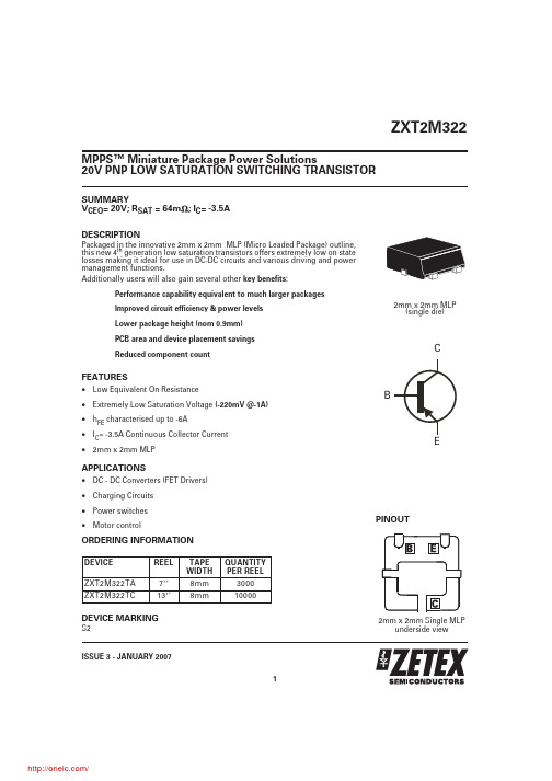
SUMMARYV CEO = 20V;R SAT = 64m ;I C = -3.5A DESCRIPTIONPackaged in the innovative 2mm x 2mm MLP (Micro Leaded Package)outline,this new 4th generation low saturation transistors offers extremely low on state losses making it ideal for use in DC-DC circuits and various driving and power management functions.Additionally users will also gain several other key benefits :Performance capability equivalent to much larger packages Improved circuit efficiency & power levels Lower package height (nom 0.9mm)PCB area and device placement savings Reduced component countFEATURES•Low Equivalent On Resistance•Extremely Low Saturation Voltage (-220mV @-1A)•h FE characterised up to -6A•I C = -3.5A Continuous Collector Current •2mm x 2mm MLPAPPLICATIONS•DC - DC Converters (FET Drivers)•Charging Circuits •Power switches •Motor controlORDERING INFORMATIONDEVICE MARKINGS2ZXT2M322ISSUE 3 - JANUARY 20071MPPS™Miniature Package Power Solutions20V PNP LOW SATURATION SWITCHING TRANSISTOR2mm x 2mm Single MLPunderside viewPINOUTDEVICE REEL TAPE WIDTH QUANTITY PER REELZXT2M322TA 78mm 3000ZXT2M322TC138mm100002mm x 2mm MLP(single die)ZXT2M322ISSUE 3 - JANUARY 20072PARAMETERSYMBOL VALUE UNIT Junction to Ambient (a)R θJA 83°C/W Junction to Ambient (b)R θJA 51°C/W Junction to Ambient (d)R θJA 125°C/W Junction to Ambient (e)R θJA42°C/WTHERMAL RESISTANCENOTES(a) For a single device surface mounted on 10sq cm1oz copper on FR4 PCB in still air conditions with all exposed pads attached .(b) For a single device surface mounted on 10sq cm1oz copper on FR4 PCB in still air conditions measured at t р5 secs with all exposed pads attached.(c) Repetitive rating - pulse width limited by max junction temperature. refer to Transient Thermal Impedance graph.(d) For a single device surface mounted on 10sq cm1oz copper on FR4 PCB in still air conditions with minimal lead connections only .(e) For a single device surface mounted on 65sq cm2oz copper on FR4 PCB in still air conditions with all exposed pads attached .(f) The minimum copper dimensions required for mounting are no smaller than the exposed metal pads on the base of the device, as shown in the package dimensions data. The thermal resistance for a device mounted on 1.5mm thick FR4 board using minimum copper of 1oz weight is Rth=300°C/W giving a power rating of Ptot=420mW.PARAMETERSYMBOL LIMIT UNIT Collector-Base Voltage V CBO -25V Collector-Emitter Voltage V CEO -20V Emitter-Base Voltage V EBO -7.5V Peak Pulse Current (c)I CM -6A Continuous Collector Current (a)I C -3.5A Base CurrentI B -1000mA Power Dissipation at TA=25°C (a)Linear Derating FactorP D 1.512W mW/°C Power Dissipation at TA=25°C (b)Linear Derating FactorP D 2.4519.6W mW/°C Power Dissipation at TA=25°C (d)Linear Derating FactorP D 18W mW/°C Power Dissipation at TA=25°C (e)Linear Derating FactorP D 324W mW/°C Operating and Storage Temperature RangeT j :T stg-55 to +150°CABSOLUTE MAXIMUM RATINGS.ZXT2M322ISSUE 3 - JANUARY 20073CHARACTERISTICSCHARACTERISTICSZXT2M322ISSUE 3 - JANUARY 20074PARAMETERSYMBOL MIN.TYP.MAX.UNIT CONDITIONS.Collector-Base Breakdown VoltageV (BR)CBO -25-35V I C =-100A Collector-Emitter Breakdown VoltageV (BR)CEO -20-25V I C =-10mA*Emitter-Base Breakdown Voltage V (BR)EBO -7.5-8.5V I E =-100A Collector Cut-Off Current I CBO -25nA V CB =-20V Emitter Cut-Off CurrentI EBO -25nA V EB =-6V Collector Emitter Cut-Off Current I CES -25nA V CES =-16VCollector-Emitter Saturation VoltageV CE(sat)-19-170-190-240-225-30-220-250-350-300mV mV mV mV mVI C =-0.1A,I B =-10mA*I C =-1A,I B =-20mA*I C =-1.5A,I B =-50mA*I C =-2.5A,I B =-150mA*I C =-3.5A,I B =-350mA*Base-Emitter Saturation Voltage V BE(sat)-1.01-1.075V I C =-3.5A,I B =-350mA*Base-Emitter Turn-On Voltage V BE(on)-0.87-0.95VI C =-3.5A,V CE =-2V*Static Forward Current Transfer Ratioh FE3003001501547545023030I C =-10mA,V CE =-2V*I C =-0.1A,V CE =-2V*I C =-2A,V CE =-2V*I C =-6A,V CE =-2V*Transition Frequency f T 150180MHz I C =-50mA,V CE =-10V f=100MHzOutput Capacitance C obo 2130pF V CB =-10V,f=1MHz Turn-On Time t (on)40ns V CC =-10V,I C =-1A I B1=I B2=10mATurn-Off Timet (off)670nsELECTRICAL CHARACTERISTICS (at T amb = 25°C unless otherwise stated).*Measured under pulsed conditions. Pulse width=300µs. Duty cycle ≤2%ISSUE 3 - JANUARY 20075ZXT2M322ISSUE 3 - JANUARY 20076EuropeZetex GmbH Balan-straße 59D-81541 München GermanyTelefon: (49) 89 45 49 49 0Fax: (49) 89 45 49 49 49europe.sales@AmericasZetex Inc700 Veterans Memorial Hwy Hauppauge, NY11788USATelephone: (631) 360 2222Fax: (631) 360 8222usa.sales@Asia PacificZetex (Asia) Ltd3701-04Metroplaza, Tower 1Hing Fong Road Kwai Fong Hong KongTelephone: (852) 26100 611Fax: (852) 24250 494asia.sales@Corporate Headquarters Zetex Semiconductors plc Zetex Technology Park ChaddertonOldham, OL9 9LL United KingdomTel: (44) 161 622 4444Fax: (44) 161 622 4446hq@These offices are supported by agents and distributors in major countries world-wide.This publication is issued to provide outline information only which (unless agreed by the Company in writing)may not be used,applied or reproduced for any purpose or form part of any order or contract or be regarded as a representation relating to the products or services concerned.The Company reserves the right to alter without notice the specification,design,price or conditions of supply of any product or service.For the latest product information,log on to©ZetexSemiconductors plc 2007CONTROLLING DIMENSIONS IN MILLIMETRES APPROX. CONVERTED DIMENSIONS IN INCHESMLP322 PACKAGE OUTLINE (2mm x 2mm Micro Leaded Package)DIM MILLIMETRESINCHES DIM MILLIMETRES INCHES MIN.MAX.MIN.MAX.MIN.MAX.MIN.MAX.A 0.80 1.000.03150.0393e 0.65REF 0.0255REF A10.000.050.000.002E 2.00BSC 0.0787BSC A20.650.750.02550.0295E20.790.990.0310.039A30.150.250.00590.0098E40.480.680.01880.0267b 0.180.280.00700.0110L 0.200.450.00780.0177b10.170.300.00660.0118L20.125MAX.0.005REF D 2.00BSC 0.0787BSCr 0.075BSC 0.0029BSC D2 1.22 1.420.04800.0559⍜0Њ12Њ0Њ12ЊD40.560.760.02200.0299PACKAGE DIMENSIONS分销商库存信息: DIODESZXT2M322TA。
- 1、下载文档前请自行甄别文档内容的完整性,平台不提供额外的编辑、内容补充、找答案等附加服务。
- 2、"仅部分预览"的文档,不可在线预览部分如存在完整性等问题,可反馈申请退款(可完整预览的文档不适用该条件!)。
- 3、如文档侵犯您的权益,请联系客服反馈,我们会尽快为您处理(人工客服工作时间:9:00-18:30)。
BOTTOM
.10 typ. wall
PART NO. 1-1-I WM01 6005
DESCRIPTION (Included) TOP BOTTOM #4 self tapping screw (4)
ACCSESSORIES (Optional) PART NO. 50 PS-11 310 410 DESCRIPTION Non-skid Feet Perimeter Seal Prototype grid board (Horiz) Prototype clad board (Horiz)
芯天下--/
ACCSESSORIES (Optional) PART NO. 50 PS-11 310 410 DESCRIPTION Non-skid Feet Perimeter Seal Prototype grid board (Horiz) Prototype clad board (Horiz)
Notes: 1) Enclosure meets or exceeds IP40 and NEMA 1 2) When used with PS-11 the enclosure meets or exceeds IP 67 and NEMA 4X, 12 and 13 MIL-STD-810G 506.5 3) Circuit Board drawings can be download at: ALL DIMENSIONS ARE ± .010" 5/7/09 (1 of 2) /Accessories/CircuitBoard/drawings/310-410.pdf 619 Commercial Ave. Covina, CA 91723 4) All components are RoHS Compliant. Ph. (626) 331-0517 Fx. (626) 331-8584
Notes: 1) Enclosure meets or exceeds IP40 and NEMA 1 .23 typ. 2) When used with PS-11 the enclosure meets or exceeds 4 plc's IP 67 and NEMA 4X, 12 and 13 MIL-STD-810G 506.5 3) Circuit Board drawings can be download at: /Accessories/CircuitBoard/drawings/310-410.pdf 4) All components are RoHS Compliant.
2.25
.30
3.25 Insert Area Non-Textured 0.015" recessed .78
PART NO. 1-1-I WM01 6005
Water proofing gasket PS-11 optional. see note #2
DESCRIPTION (Included) TOP BOTTOM #4 self tapping screw (4)
SECTION A-A SCALE 1 : 1.5
.32 typ. 4 plc's
Ph. (626) 331-0517 Fx. (626) 331-8584
ALL DIMENSIONS ARE ± .010" 5/7/09 (2 of 2) 619 Commercial Ave. Covina, CA 91723
芯天下--/
WM011-I (user print)
1.90 Insert Area 1.10 .30 .02 .12 6 plc's .25 4 plc's 2.32
A
1.50
4.09 3.25 Insert Area
1.00
3.60
2.85
4.61
.14 6 plc's for #4 screws
WM011-I(exploded isometric)
PN 6005 (4) Self tapping screws
1.10 Height
WM01
2.32 3.60
4.61
1-1-I
1.90 Insert Area Non-Textured 0.015" recessed .14 typ. 6 plc's for # 4 screws
5° typ.
A
1.80
Insert Area Non-Textured 0.015" recessed
.10
1.50
2.25
.09 typ. for #4 screw
TOP
பைடு நூலகம்
.31 typ. 4 plc's
Insert Area .015 recessed
.26 typ. .26 typ. 4 plc's