MS103 2007Apr presentation for customer
NPort 6150 6250 Series Quick Installation Guide

P/N: 1802061500016 *1802061500016*NPort 6150/6250 Series Quick Installation GuideEdition 9.0, November 2016Technical Support Contact Information/supportMoxa Americas:Toll-free: 1-888-669-2872 Tel: 1-714-528-6777 Fax: 1-714-528-6778 Moxa China (Shanghai office): Toll-free: 800-820-5036 Tel: +86-21-5258-9955 Fax: +86-21-5258-5505 Moxa Europe:Tel: +49-89-3 70 03 99-0 Fax: +49-89-3 70 03 99-99 Moxa Asia-Pacific:Tel: +886-2-8919-1230 Fax: +886-2-8919-1231 Moxa India:Tel: +91-80-4172-9088 Fax: +91-80-4132-10452016 Moxa Inc. All rights reserved.OverviewThe NPort 6150/6250 series secure serial device servers provide reliable serial-to-Ethernet connectivity for a wide range of serial devices. The NPort 6150/6250 support TCP Server, TCP Client, UDP, andPair-Connection operation modes to ensure the compatibility of network software. In addition, the NPort 6150/6250 also support Secure TCP Server, Secure TCP Client, Secure Pair-Connection, and Secure Real COM modes for security critical applications such as banking, telecom, access control, and remote site management.Package ChecklistBefore installing a NPort 6150/6250 secure device server, verify that the package contains the following items:• 1 NPort 6150 or NPort 6250•Power adapter (does not apply to -T models)• 2 wallmount ears•Documentation and software CD•Quick installation guide (this guide)•Warranty cardOptional Accessories•DK-35A: DIN-rail mounting kit (35 mm)•DIN-rail power supply•CBL-RJ45M9-150: 8-pin RJ45 to male DB9 cable•CBL-RJ45M25-150: 8-pin RJ45 to male DB25 cableNOTE: Please notify your sales representative if any of the above items are missing or damaged.Hardware IntroductionNPort 6150NPort 6250Reset Button—Press the Reset Button continuously for 5 sec to load factory defaults. Use a pointed object, such as a straightened paper clip or toothpick, to press the reset button. This will cause the Ready LED to blink on and off. The factory defaults will be loaded once the Ready LED stops blinking (after about 5 seconds). At this point, you should release the reset button.LED IndicatorsAdjustable pull high/low resistor for RS-422/485 (150 K Ω or 1 K Ω)Jumpers are used to set the pull high/low resistors. The default is 150 kΩ. Short the jumpers to set this value to 1 kΩ. Do not use the 1 kΩ setting with RS -232 mode, since doing so will degrade the RS-232 signals and shorten the communication distance.Hardware Installation ProcedureSTEP 1: Connect the 12-48 VDC power adaptor to the NPort 6150 andthen plug the power adaptor into a DC outlet.STEP 2: For first-time configuration, use a cross-over Ethernet cable toconnect the NPort 6150 directly to your computer’s Ethernet cable. For connecting to a network, use a standardstraight-through Ethernet cable to connect to a hub or switch.STEP 3: Connect the NPort 6150’s serial port to a serial device.Placement OptionsThe NPort 6150/6250 can be placed flat on a desktop or other horizontal surface. In addition, you may use the DIN-rail or wallmount options, as illustrated below.WallmountDin RailSoftware Installation InformationThe Documentation and software CD contains the user’s manual, NPort Search Utility, and the PComm Lite Suite. Insert the CD into yourcomputer’s CD-ROM drive and follow the on-screen instructions. Please refer to the user’s manual for additional details on using the NPort Search Utility and PComm Lite.Pin Assignments and Cable WiringTwo serial cables for connecting the NPort 6150 to a serial device can be purchased separately. The wiring diagrams for the two cables are shown below.。
Ovation I O Reference Manual

This publication adds the Eight Channel RTD module to the Ovation I/O Reference Manual. It should be placed between Sections 19 and 20.Date: 04/03IPU No.243Ovation ® Interim Publication UpdatePUBLICATION TITLEOvation I/O Reference ManualPublication No. R3-1150Revision 3, March 2003Section 19A. Eight Channel RTDModule19A-1. DescriptionThe Eight (8) channel RTD module is used to convert inputs from Resistance Temperature Detectors (RTDs) to digital data. The digitized data is transmitted to the Controller.19A-2. Module Groups19A-2.1. Electronics ModulesThere is one Electronics module group for the 8 channel RTD Module:n5X00119G01 converts inputs for all ranges and is compatible only with Personality module 5X00121G01 (not applicable for CE Mark certified systems).19A-2.2. Personality ModulesThere is one Personality module groups for the 8 channel RTD Module:n5X00121G01 converts inputs for all ranges and is compatible only with Electronics module 5x00119G01 (not applicable for CE Mark certified systems).19A-2.3. Module Block Diagram and Field Connection WiringDiagramThe Ovation 8 Channel RTD module consists of two modules an electronics module contains a logic printed circuit board (LIA) and a printed circuit board (FTD). The electronics module is used in conjunction with a personalty module, which contains a single printed circuit board (PTD). The block diagram for the 8 channel RTD moduleis shown in Figure 19A-1.Table 19A-1. 8 Channel RTD Module Subsystem ChannelsElectronic Module Personality Module85X00119G015X00121G01Figure 19A-1. 8 Channel RTD Module Block Diagram and Field Connection Wiring Diagram19A-3. SpecificationsElectronics Module (5X00119)Personality Module (5X00121)Table 19A-2. 8 Channel RTD Module SpecificationsDescription ValueNumber of channels8Sampling rate50 HZ mode: 16.67/sec. normally. In 3 wire mode, leadresistance measurement occurs once every 6.45 sec.during which the rate drops to 3/sec.60 HZ mode: 20/sec. normally. In 3 wire mode, leadresistance measurement occurs once every 6.45 sec.during which the rate drops to 2/sec.Self Calibration Mode: Occurs on demand only. The ratedrops to 1/sec. once during each self calibration cycle.RTD ranges Refer to Table 19A-3.Resolution12 bitsGuaranteed accuracy (@25°C)0.10% ±[0.045 (Rcold/Rspan)]% ± [((Rcold + Rspan)/4096 OHM)]% ± [0.5 OHM/Rspan]% ±10 m V ± 1/2LSBwhere:Rcold and Rspan are in Ohms.Temperature coefficient 10ppm/°CDielectric isolation:Channel to channel Channel to logic 200V AC/DC 1000 V AC/DCInput impedance100 M OHM50 K OHM in power downModule power 3.6 W typical; 4.2 W maximumOperating temperature range0 to 60°C (32°F to 140°F)Storage temperature range-40°C to 85°C (-40°F to 185°F)Humidity (non-condensing)0 to 95%Self Calibration On Demand by Ovation ControllerCommon Mode Rejection120 dB @ DC and nominal power line frequency+/- 1/2%Normal Mode Rejection100 dB @ DC and nominal power line frequency+/- 1/2%Table 19A-3. 8 Channel RTD RangesScale #(HEX)Wires Type Tempo FTempo CRcold(ohm)Rhot(ohm)Excitationcurrent(ma)Accuracy± ±countsAccuracy± ±% ofSPAN1310OhmPL0 to1200–18 t o6496106.3 1.090.222310OhmCU 0 to302–18 t o1508.516.5 1.0 130.32D350OhmCU 32 to2840 to1405080 1.0110.2711350OhmCU 32 to2300 to1105378 1.0120.30193100Ohm PL –4 to334–16 t o16892163.671.0110.27223100Ohm PL 32 to5200 to269100200 1.0100.25233100Ohm PL 32 to10400 to561100301 1.0100.25253120Ohm NI –12 t o464–11 t o240109360 1.0100.25263120Ohm NI 32 to1500 to70120170 1.0130.32283120Ohm NI 32 to2780 to122120225 1.0110.27804100Ohm PL 32 to5440 to290100 208 1.0100.25814100Ohm PL 356 t o446180 t o230168 186 1.0300.74824200Ohm PL 32 to6980 to370200 473 1.0120.30834200Ohm PL 514 t o648268 t o342402452 1.0290.71844100Ohm PL 32 to1240 to51100120 1.0190.47854100Ohm PL 32 to2170 to103100 140 1.0130.3286 4100Ohm PL 32 to4120 to211100 180 1.0110.27874100Ohm PL 32 to7140 to379100 240 1.0100.25884120Ohm PL 511 t o662266 t o350200230 1.0240.5919A-4. 8 Channel RTD Terminal Block Wiring Information19A-4.1. Systems Using Personality Module 5X00121G01 Each Personality module has a simplified wiring diagram label on its side, which appears above the terminal block. This diagram indicates how the wiring from the field is to beconnected to the terminal block in the base unit. The following table lists and defines the abbreviations used in this diagram.Table 19A-4. Abbreviations Used in the DiagramAbbreviation Definition+IN, -IN Positive and negative sense input connectionEarth ground terminal. Used for landing shields when the shield is to begrounded at the module.PS+, PS-Auxiliary power supply terminals.RTN Return for current source connection.SH Shield connector. used for landing shields when the shield is to begrounded at the RTD.SRC Current source connection.Note:PS+ and PS- are not used by this module.19A-5. 8 Channel RTD Module Address Locations19A-5.1. Configuration and Status RegisterWord address 13 (D in Hex) is used for both module configuration and module status. The Module Status Register has both status and diagnostic information. The bit information contained within these words is shown in Table 19A-5.Definitions for the Configuration/Module Status Register bits:Bit 0:This bit configures the module (write) or indicates the configuration state of the module (read). A “1” indicates that the module is configured. Note that until the module is configured, reading from addresses #0 through #11 (B in Hex) will produce an attention status.Bit 1:This bit (write “1”) forces the module into the error state, resulting in the error LED being lit. The read of bit “1” indicates that there is an internal module error,or the controller has forced the module into the error state. The state of this bit is always reflected by the module’s Internal Error LED. Whenever this bit is set,an attention status is returned to the controller when address #0 through #11(B in Hex) are read.Table 19A-5. 8 Channel RTD Configuration/Status Register (Address 13 0xD in Hex)Bit Data Description -Configuration Register (Write)Data Description -Status Register (Read)0Configure Module Module Configured(1 = configured; 0 = unconfigured)1Force errorInternal or forced error(1 = forced error; 0 = no forced error)250/60 Hz select (0 = 60Hz, 1 = 50Hz)50/60 Hz System (1 = 50Hz) d(read back)3SELF_CAL (Initiates Self Calibration)Warming bit (set during power up or configuration)40050060Module Not Calibrated 708CH.1 _ 3/4 Wire.CH.1 _ 3/4 Wire - Configuration (read back)9CH.2 _ 3/4 Wire.CH.2 _ 3/4 Wire - Configuration (read back)10CH.3 _ 3/4 Wire.CH.3 _ 3/4 Wire - Configuration (read back)11CH.4 _ 3/4 Wire.CH.4 _ 3/4 Wire - Configuration (read back)12CH.5 _ 3/4 Wire.CH.5 _ 3/4 Wire - Configuration (read back)13CH.6 _ 3/4 Wire.CH.6 _ 3/4 Wire - Configuration (read back)14CH.7 _ 3/4 Wire.CH.7 _ 3/4 Wire - Configuration (read back)15CH.8 _ 3/4 Wire.CH.8 _ 3/4 Wire - Configuration (read back)Bit 2:The status of this bit (read) indicates the conversion rate of the module, write to this bit configures the conversion rate of A/D converters as shown below.see Table 19A-6.Bit3:Write: This bit is used to initiate self-calibration. Read: This bit indicates that the module is in the “Warming” state. this state exists after power up and ter-minates after 8.16 seconds. the module will be in the error condition during the warm up period.Bit4 & 5:These bits are not used and read as “0” under normal operation.Bit 6:This bit (read) is the result of a checksum test of the EEPROM. A failure of this test can indicate a bad EEPROM, but it typically indicates that the module has not been calibrated. A “0” indicates that there is no error condition. If an error is present, the internal error LED is lit and attention status will be returned for all address offsets 0-11 (0x0 - 0xB). The “1” state of this bit indicates an unre-coverable error condition in the field.Bit 7:This bits is not used and read as “0” under normal operation.Bit 8 - 15:These bits are used to configure channels 1 - 8 respectively for 3 or 4 wire op-eration. A “0” indicates 3 wire and a “1” indicates 4 wire operation, see Table 19A-7 and Table 19A-8).Word address 12 (0xC) is used to configure the appropriate scales for Channels 1 - 4 (refer to Table 19A-7 and Table 19A-8).Table 19A-6. Conversion Rate Conversion Rate (1/sec.)Bit 260 (for 60Hz systems)050 (for 50Hz systems)1Table 19A-7. Data Format for the Channel Scale Configuration Register(0xC)Bit Data Description Configuration (Write)Data Description Status (Read)0 Configure Channel #1scale - Bit 0Channel #1 scale configuration (read back) - Bit 01Configure Channel #1scale - Bit 1Channel #1 scale configuration (read back) - Bit 12Configure Channel #1scale - Bit 2Channel #1 scale configuration (read back) - Bit 23Configure Channel #1scale - Bit 3Channel #1 scale configuration (read back) - Bit 34Configure Channel #2 scale - Bit 0Channel #2 scale configuration (read back) - Bit 05Configure Channel #2 scale - Bit 1Channel #2 scale configuration (read back) - Bit 16Configure Channel #2 scale - Bit 2Channel #2 scale configuration (read back) - Bit 27Configure Channel #2 scale - Bit 3Channel #2 scale configuration (read back) - Bit 38Configure Channel #3 scale - Bit 0Channel #3 scale configuration (read back) - Bit 09Configure Channel #3 scale - Bit 1Channel #3 scale configuration (read back) - Bit 1Caution:Configuring any or all channel scales while the system is running will cause all channels to return attention status for up to two seconds following the reconfiguration.Caution:Configuring any or all channel scales while the system is running will cause all channels to return attention status for up to two seconds following the reconfiguration.10Configure Channel #3 scale - Bit 2Channel #3 scale configuration (read back) - Bit 211Configure Channel #3 scale - Bit 3Channel #3 scale configuration (read back) - Bit 312Configure Channel #4 scale - Bit 0Channel #4 scale configuration (read back) - Bit 013Configure Channel #4 scale - Bit 1Channel #4 scale configuration (read back) - Bit 114Configure Channel #4 scale - Bit 2Channel #4 scale configuration (read back) - Bit 215Configure Channel #4 scale - Bit 3Channel #4 scale configuration (read back) - Bit 3Table 19A-8. Data Format for the Channel Scale Configuration Register(0xE)Bit Data Description Configuration (Write)Data Description Status (Read)0 Configure Channel #5 scale - Bit 0Channel #5 scale configuration (read back) - Bit 01Configure Channel #5 scale - Bit 1Channel #5 scale configuration (read back) - Bit 12Configure Channel #5 scale - Bit 2Channel #5 scale configuration (read back) - Bit 23Configure Channel #5 scale - Bit 3Channel #5 scale configuration (read back) - Bit 34Configure Channel #6 scale - Bit 0Channel #6 scale configuration (read back) - Bit 05Configure Channel #6 scale - Bit 1Channel #6 scale configuration (read back) - Bit 16Configure Channel #6 scale - Bit 2Channel #6 scale configuration (read back) - Bit 27Configure Channel #6 scale - Bit 3Channel #6 scale configuration (read back) - Bit 38Configure Channel #7 scale - Bit 0Channel #7 scale configuration (read back) - Bit 09Configure Channel #7 scale - Bit 1Channel #7 scale configuration (read back) - Bit 110Configure Channel #7 scale - Bit 2Channel #7 scale configuration (read back) - Bit 211Configure Channel #7 scale - Bit 3Channel #7 scale configuration (read back) - Bit 312Configure Channel #8 scale - Bit 0Channel #8 scale configuration (read back) - Bit 013Configure Channel #8 scale - Bit 1Channel #8 scale configuration (read back) - Bit 114Configure Channel #8 scale - Bit 2Channel #8 scale configuration (read back) - Bit 215Configure Channel #8 scale - Bit 3Channel #8 scale configuration (read back) - Bit 3Table 19A-7. Data Format for the Channel Scale Configuration Register(0xC)19A-6. Diagnostic LEDsTable 19A-9. 8 Channel RTD Diagnostic LEDsLED DescriptionP (Green)Power OK LED. Lit when the +5V power is OK.C (Green)Communications OK LED. Lit when the Controller is communicatingwith the module.I (Red)Internal Fault LED. Lit whenever there is any type of error with themodule except to a loss of power. Possible causes are:n - Module initialization is in progress.n - I/O Bus time-out has occurred.n - Register, static RAM, or FLASH checksum error.n - Module resetn - Module is uncalibrated.n - Forced error has been received from the Controllern - Communication between the Field and Logic boards failedCH1 - CH 8 (Red)Channel error. Lit whenever there is an error associated with a channel or channels. Possible causes are:n - Positive overrangen - Negative overrangen Communication with the channel has failed。
yt14.3-2007

yt14.3-2007英文回答:Introduction.The standard YT14.3-2007 provides a comprehensive framework for the design, construction, and testing of steel structures. It is widely used in the construction industry to ensure the safety and reliability of steel structures. This article will discuss the key requirements of YT14.3-2007, including material specifications, design principles, construction methods, and testing procedures.Material Specifications.YT14.3-2007 specifies the minimum requirements for the materials used in steel structures. These requirements include the chemical composition, mechanical properties, and physical properties of the steel. The standard also provides guidelines for the selection and use of differenttypes of steel, such as carbon steel, alloy steel, and stainless steel.Design Principles.The design principles outlined in YT14.3-2007 are based on the theory of structural mechanics. These principles include the concepts of stress, strain, and deformation. The standard provides formulas and equations forcalculating the stresses and strains in steel structures under various loading conditions. The design principles also address the issues of stability, ductility, andfatigue resistance.Construction Methods.YT14.3-2007 provides guidance on the construction methods used for steel structures. These methods include welding, bolting, and riveting. The standard specifies the minimum requirements for each of these methods, including the type of equipment to be used, the preparation of the steel surfaces, and the inspection procedures.Testing Procedures.YT14.3-2007 requires that steel structures be tested to ensure their safety and reliability. These tests include load tests, non-destructive tests, and destructive tests. The load tests are used to verify the structural integrity of the steel structure under various loading conditions. The non-destructive tests are used to detect any defects or flaws in the steel structure. The destructive tests are used to determine the ultimate strength and ductility of the steel structure.Conclusion.YT14.3-2007 is a comprehensive standard that provides the requirements for the design, construction, and testing of steel structures. The standard is widely used in the construction industry to ensure the safety and reliability of steel structures. By following the requirements ofYT14.3-2007, engineers and contractors can ensure thatsteel structures are built to the highest standards ofquality and safety.中文回答:引言。
RELM EPI 3101AV HF 无线电设备说明书
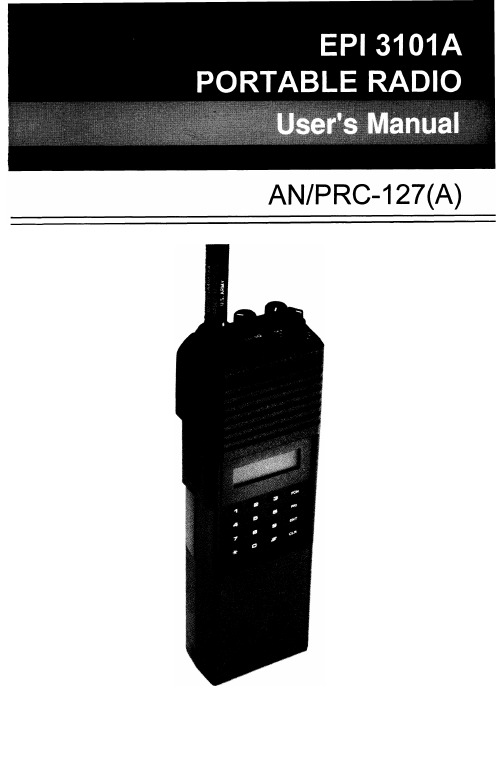
TABLE OF CONTENTS Introduction (1)Preparation For Use (2)Keyboard/Display Cover (2)Battery Installation (2)Antenna Installation (2)Radio Controls (3)Basic Operation (4)Detailed Operation (5)Display (5)Keyboard (5)Volume Control (5)Squelch Control (6)Channel Groups (6)PTT Switch (7)Code Guard Operation (8)Programming (9)Programming- Keyboard Method (9)Cloning (23)Programming From A Computer (26)Accessories (27)INTRODUCTIONThis manual covers the operation and programming procedures for RELM’s model EPI 3101AVHF Radio. The Radio provides two-way FM communication on up to 28 channels, over a frequency range of 136 to 160 MHz, with an RF output of 3 watts.This synthesized portable utilizes a microprocessor core allowing features and performance designed to meet the requirements of a commercial NDI NSUR as detailed in the Purchase Description, AN/PRC-127(A) Radio Set. Using the information in this manual will help assure optimum and proper performance from the Radio.The Radio Set consists of the EPI 3101A Radio and the following accessory items: LAAO126 Rechargeable Nickel-Cadmium Battery (2), LAA0312A Battery Charger, LAA0117 Battery Holder for 9 replaceable AA batteries, LAA0818A Flexible Antenna, LAA0203A External Speaker/ Microphone and LAA0445A Carrying Case. All of these items, except for the Radio, are shown on page 27.EPI 3101A User’s Manual1PREPARATION FOR USEKEYBOARD/DISPLAY COVERTo remove or install the Keyboard/Display Cover, remove the battery if installed. The Cover slides in grooves and latches at its bottom edge. BATTERY INSTALLATIONA.Battery packs are available as a rechargeable type (LAA0126) oras a non-rechargeable type (LAA01 17). Rechargeable battery packs can be charged separately or while attached to a radio.NOTE: For safety reasons, rechargeable battery packs are shipped uncharged or only partially charged. Therefore, a recharge-able battery pack should be properly charged before use.B.To install the battery pack, locate the center hub on the radio baseand place it in the recess of the battery pack. Position the pack at the 30” offset, seating two metal studs in their recess. Apply upward pressure to the pack while twisting the pack to its original position.The metal tab will click, locking the pack in position.C.To remove the battery pack, first turn the radio off. Then, as shownabove, push up the metal tab on the side of the case while twisting the battery pack approximately 30° and remove it from the radio.NOTE: All information programmed into the radio is maintained even when the battery pack is removed.D.Periodically check the contacts on the battery pack for dirt that mayprevent a good electrical contact with the charging base.WARNING:Do not dispose of a battery pack in fire.An explosion may occur.ANTENNA INSTALLATIONInsert the flexible helical-wound antenna (LAA0818A) into the Unit’s antenna connector and turn it clockwise until it is firmly seated.27-SEGMENT LIQUID CRYSTAL DISPLAYSPEAKERM I C R O P H O N ELCD DISPLAYK E Y B O A R D EPI 3101A User’s Manual3BASIC OPERATIONTRANSMITFunction - Used only in Programming ModeClear (Erase) - Used in Operational andSQUELCH CONTROLRotate the Squelch Control (CG-SQ) Knob clockwise from its detent (CG) position in order to hear any transmissions, regardless if they are tone or digital coded or not. This, in effect,. is the Radio’s MONITOR position. Turning the Squelch Control further clockwise until “noise” is heard permits the Volume Control to be adjusted to a desired level, even though an actual signal is not present.CHANNEL GROUPS510411312213114SELECT A GROUPGROUP NUMBER The Channel Selector knob has 14 positions. The Radio has 28 channels which are separated into two “groups” of 14 channels each. Group 01 is factory programmed for narrow channel (12.5kHz) FM reception. Channel Group 02 is programmed for wide channel (25 kHz) FMreception. Use Group 02 for proper communicationwith the original AN/PRC-127 Radio.P RESS THE #KEY on the keyboard to display the current Channel Group number. If it isn’t the desired Group, proceed to the next step.P RESS A NUMBER KEYfor the new Group number.P RESS THE ENTKEY or wait about 5 seconds; the radio returns to normal operation for the newgroup, and the channel corresponding to theChannel Selector’s position is displayed in theLCD.If an invalid number is selected (05 for example)when selecting a Channel Group, the LCD displaysnogrp05 (no Group 05) immediately if ENT ispressed, or in about 5 seconds if not pressed.Then, after 5 seconds, the radio returns to thepreviously selected group.6Rotate the Channel Selector knob to the desired channel. Please note that not all 14 channels may be programmed. Therefore, select only an authorized (programmed) channel for communication purposes.PTT SWITCHChCODE GUARD OPERATIONCode GuardTM, Tone or Digital, allows one radio or group of radios to be selectively called within a system. If the radio has been programmed with Code Guard, use the following receive and transmit instructions. CODE GUARD RECEIVETURN POWER ON by turning the Volume knobclockwise past the OFF detent.S ELECT A C ODE G UARD CHANNEL by turning theChannel Selector knob.A DJUST VOLUME by turning the Squelch knobclockwise until a rushing noise is heard, thenturning the Volume knob to a comfortable level.S ET C ODE G UARD MODE by turning the Squelchknob completely counterclockwise, past the detentto the CG position. A message will be heard onlywhen the proper Code Guard value is received.CODE GUARD TRANSMITT URN THE S QUELCH KNOB clockwise, off the detent.M ONITOR THE C ODE G UARD CHANNEL beforetransmitting.P RESS THE PTT (Push-To-Talk) switch if thechannel is not busy (signal is not present). Whenthe transmitter is activated, the LCD goes blank.R ESET THE S QUELCH KNOB to the Code Guardposition (CG) to receive only the messages withthe proper Code Guard value. During extendedtransmissions the squelch can be left open (offthe detent) until the exchange has ended.Code Guard is a trademark of BK Radio, Inc.8PROGRAMMINGThere are three different ways to program an EPI 3101A radio:A.It can be programmed and/or reviewed using its internal keyboard.This section of the manual describes that procedure.B.Another radio (MASTER) with the desired information can transferits programmed settings to the radio (SLAVE) by using a cloning cable, LAA0700. See “Cloning” on page 23.C.It can be programmed from a computer by using a special RS-232interface cable. That procedure is not described in this manual.See page 26 for more details.PROGRAMMING - KEYBOARD METHODRadios are shipped with a removable door covering the keyboard and display. Before programming or reviewing, remove the door. First, remove the battery pack if installed. Then, engaging the door just below the speaker grill, slide the door downward. Reinstall the battery pack. Make sure the battery pack is charged.1.Turn the radio on.2.Select the Channel Group to beprogrammed or reviewed.3.Press and hold the FCN key. Afterapproximately three seconds, the LCD willdisplay ---Id.4.Release the FCN key. The radio is now inthe password entry mode.5.Enter the six-digit Password Code.IMPORTANT: VVithout the correct PasswordCode, you cannot proceed with reviewingor programming. The same PasswordCode is used for both Channel Groups.New radios shipped from the factory areassigned the Password Code 000000.While entering the Password Code, thedisplay will not change, but a beep willsound for each key pressed. If thePassword Code is entered incorrectly, theradio will reset to normal operation. Tryagain, starting at step 3.EPI 3101A User’s Manual96.To keep the Password Code unchanged,press the ENT key and continue with normalradio programmingTo change the Password Code, press theFCN key and enter a new six-digit passwordcode. The’digits are now displayed as youenter them. The Password Code cancontain the digits 0 through 9, *, and #. The* is represented as a b and the # isrepresented as an A in the display.IMPORTANT: Do NOT use a 1 for the first digitof the Password Code - the radio willmalfunction. It will then require using acomputer program to correct the PasswordCode and put the radio back into normaloperating condition.If you make an errorwhile entering the newPassword Code, press the CLR key andtry again.7.Press the ENT key to store the newPassword Code and proceed to theprogramming mode. The display willchange to PROG Ch 0. The Radio is nowready for Reviewing and/or Programming. TO REVIEW GENERAL RADIO PERFORMANCE VARIABLES (CHANNEL 0):Channel 0 is the portion of the program that controls the general performance variables for each Group of 14 channels in a 28-channel radio. Thus, the Channel 0 settings for each Channel Group must be reviewed or programmed separately.NOTE: Settings listed as Group One Functions and Group Two Functions refer to reviewing or programming Function Groups,not the two Channel Groups 01 and 02.10Channel 0 Settings for each Channel Group include:Factory ProgramD e s c r i p t i o n Setting D i s p l a yID or Automatic Number Identification (ANI)’12345671234567 Transmit Timeout Timer disabled0 sec. Scan Delay Time disabled0.0 sec. Group One Functions 1-12345Battery Saver lnhibit 1-1 (See Note 3)disabled1-12345 Priority Scan Operation 1-2 &3disabled1-12345\I/ Priority Key Lockout 1-4enabled1-12345/I\\I/ Scan List Lockout 1-5enabled1-1for example, indicates that Function (l-1) is enabled and itscorresponding number(s) in the display is flashing. W h e n aFunction is disabled, its corresponding number(s) is steady. EPI 3101A User’s Manual1111.After entering the program mode,the display will show PROG Ch 0.2.Press CLR and then press the digit key(s) of the channel that needs to be reviewed. The display will show the channel to be reviewed.3.Press the FCN key. The display will show the receive frequency in MHz.4.Press the FCN key. The display will show the receive Tone Code Guard or Digital Code Guard (the value 0.0denotes carrier squelch). Digital Code Guard will be a three digit number preceded by a d in the display.DIGITAL CODEP R O G 1.Battery Saver Inhibit - If needed,press the 1 key to change the BatterySaver’s status.BATTERY SAVER ONREMINDER: If 1 is steady, theBattery Saver Inhibit is disabled, EPI 3101A User’s Manual152 & 3.4 ICHANNEL NOT CHANGEABLE SCAN LIST NOT CHANGEABLEFunctions 2 and 3 are used to definePriority Scan operation. SincePriority Scan is not available, both 2and 3 should be steady.PRI Key Lockout-When enabled (flashing) the PRI key will be locked out in the operating mode. Because the PRIORITY feature is not available, the 4 should be flashing.Scan List Lockout - VVhen enabled (flashing), the User will not be able to change the channels in the scan list. Since SCAN is not available,the 5 should be flashing.Once each function l-5 is set as desired, press ENT to store them into memory and automatically advance the program to the next section.If no changes have been entered,press FCN to advance to the next section.F.Miscellaneous Channel 0 Programming-GROUPTWO FUNCTIONSAfter Group 1 functions are set, the display will show PROG 2-12345for,I J NO RECEIVE FREQUENCY 1.Press 1, for example, and the displaywill show PROG Ch 1. This is theentry point for channel 1 values. 2.Press FCN. The display will showPROG RX and the ReceiveFrequency (in MHz) for channel 1.RX stands for Receive Frequency.If the channel has not beenprogrammed yet, the display willshow PROG RX 0.0.3.If the displayed frequency is correct,press FCN to advance to the nextvalue.To initially program the frequency orif a new frequency is desired, pressCLR followed by the digits of thedesired frequency from left to right.Then press ENT to store this , frequency and automatically advance to the next value.See Table 1 on page 18 for properfrequency increments.EPI 31OlA Usefs Manual17lOkHz(O-9)1kHz(0,2 or5)1kHz(O or 5)ITable 1. Proper Frequency Increments.184.After the Receive Frequency is set,the upper part of the display willshow PROG RX CG. This is theCode Guard value for Channel 1receive. Note: 0.0 indicates carriersquelch operation.If the displayed value is correct, pressFCN to advance to the next value.If a new value is desired, press theCLR key to reset the display to 0.0.Tone Code Guard is entered directly,using the digit keys (0 through 9).See pages 21 and 22 for properCode Guard values.Digital Code Guard is entered byfirst pressing CLR, then the # key,causing the letter d to appear,7xSELECTING A TONE CODE GUARDThe Tone Code Guard system (CTCSS) may be set for any frequency in the range of 67 to 250.3 Hz. However, since most systems adhere to the Electronic Industry Association (EIA) standards, tones should be selected from the following EIA list.In order to insure optimum performance tone selection for use on the same radio frequency (RF) channel or adjacent channels in the same coverage area should be made from one of the Groups A, B, or C as much as possible. RELM guarantees optimum receiver performance only if tone frequencies below 220 Hz are chosen.GROUP A GROUP B GROUP C67.0 77.0 88.5 *100.0 107.2 114.8 123.0 131.8 141.3*151.471.9146.274.4 162.282.5156.779.7 173.894.8167.985.4 186.2103.5“179.991.5 203.5100.9192.8218.1*118.8210.7233.6127.3225.7250.3136.5241.8*50/60 Hz power distribution systems could cause falsing.The assignments in a given area shall be made from one of the Groups A, B, or C as much as possible.EPI 3101A User’s Manual21SELECTING A DIGITAL CODE GUARDCodes for the Digital Code Guard system (CDCSS) may be chosen from the following list. For the performance or compatibility of Digital Code Guard systems, it is recommended that an operational test be made on the intended system before wholesale assignments are made.In some cases, either one or both the transmit and receive codes will require an inverted code* to operate with existing systems. This can be done during the code programming of the system.Usually, systems using direct unit to unit transmission (systems without mobile relays, repeaters, remote control, etc.) may use codes from the table. Systems with relays, etc. may use code variations for system control and operational efficiency. The system operator or engineer should be consulted regarding the operational requirement on such systems.023065 131 172 251 331 412 466 612 703 025071132 174 261 343 413 503 624 712 026072 134 205 263 346 423 506 627 723 031073 143 223 265 351 431 516 631 731 032074 152 226 271 364 432 532 632 732 043114 155 243 306 365 445 546 654 734 047115 156 244 311 371 464 565 662 743 051116 162 245 315 411 465 606 664 754 054125 165*NOTE: Inverted code is displayed with a "-" following the Digital Code’s value. See page 20 for an example.2289Press the * key on the MASTERradio keyboard. The display will flashPROG signifying that the radio isready to download its program to theCLONE.Press the FCN key on the MASTERradio keyboard. The program in theMASTER will then be downloadedto the CLONE. The CLONE willautomatically send back the programto the MASTER to verify a successfulcloning.10. If the download was successful, theMASTER’s display will resumeflashing PROG.A.To clone the other ChannelGroup, power down both radiosand go to Step 3, changing theChannel Group as required.B.If finished cloning, power downthe CLONE and disconnect thecloning cable. Normal radiooperation will occur on theCLONE’s next power up.11. If the download was not successful,the MASTER will display FAIL andmultiple beeps will follow. Failure ofdownloading can be due to:A. Improper connectionB.Failure to power up CLONEC.CLONE set in the programmingmodeNOTE: To stop the FAIL mode,press CLR, power down both radiosand try again, starting at step 1 onpage 23.24SPECIAL CLONING INSTRUCTIONSIt is possible to change Channel 0 values on the MASTER radio, hold them in a temporary memory, and download them to the CLONE without actually entering them into the permanent memory of the MASTER. This is convenient if sequential identification numbers are used to identify a series of portables in a radio system. Assuming that the frequencies,Code Guard values, and other CH 0 values are common for all radios in the system, but that the radio identification number should be unique to each radio, the following method would be used to clone additional radios for the system:123456Program the MASTER with allfrequencies, Code Guard values andChannel 0 values that will becommon to all radios.Advance the display to show theMASTER’s ID number (for example100)Press CLR; press 1,2, and 5.125 isnow only in temporary memory.Press *, connect the cloning cable tothe CLONE radio and download bypressing FCN. ID number 125 isnow stored in permanent memory ofthe CLONE.After download, press CLR.Disconnect the CLONE. TheMASTER radio display will showthat 125 is still being held in thetemporary memory of the MASTER.Press PRI. This will increment theID number one digit to 126.NOTE: Any new number can be entered at this point by pressingCLR and using the digit keys toenter the new number.EPI 3101A User’s Manual 257.Press *. Connect the cloning cableto the next CLONE radio anddownload by pressing FCN.8.Any number of radios can be codedwith different or sequential IDnumbers using this technique. TheID number in the permanent memoryof the MASTER will remainunchanged as 300.PROGRAMMING FROM A COMPUTERProgramming the radio from an IBM compatible computer, using the LAA0725 Interface Cable, is covered in a separate programming manual. The manual is included with the programming software. Contact RELM Communications, Inc. to order the interface cable and software. Specify the program is for the EPI 3101A Radio.26Helical-wound flexible antenna that covers the entire range of frequencies that can be programmed into the EPI 3101A Radio.LAA0445A Carrying CaseThis textile case is built to provide proper protection while keeping the radio at your side.LAA0203A Speaker/MicrophoneThis light weight speaker/microphone clips securely to collar or lapel, offering the convenience of easy communications without removing the radio from your belt. To install the LAA0203A:1.Lift away the protective cover from the Accessory connector andEarphone jack. See Radio’s side view on page 3 for theirlocation. The protective cover can not be completely removedsince it is permanently attached near the flexible antenna’sconnector.2.Carefully install the Speaker/Microphone’s connector assemblyinto the Accessory and Earphone connectors.3.Screw in the assembly’s retaining bolt until finger tight. Do notovertighten.NOTE: VVhen the LAA0203A is removed, the protective cover should be reinstalled so that the various electricalconnections are not exposed to dust, dirt, rain, etc.28RELM Communications, Inc. 7505 Technology Drive West Melbourne, FL 32904 Telephone: (407) 984-1414 FAX: (407) 676-4403。
AVer Document Camera Setup Guide

Setup your AVer Document Camera from home!Please first identify which AVer document camera you are using to know what software to install.A+ Suite (Sphere2 on Win10/Mac) or Sphere Lite (Chromebooks): AVer U70+, AVer U50, AVer M70HD, AVer 300AFHD, AVer F70W, AVer F50-8M, AVer F17-8M, M17-13MAVerTouch (Win10/Mac): AVer M15W, AVer M15-13M, AVer M70WA+ Interactive Software (Old Version on Win/Mac): V300AF ASIC, SPC300 ASIC, SPC300 +, CP130, CP150, CP300, SPB350, SPB370, CP135, CP155, CP355, V355AF, V310AF, SPB350+, V300AF+, F30, F50, U10, U15, AP20,M50, W30Sphere (Old Version on Win/Mac): PL50, SPB350, SPB370, SPB350+, M50, M70, V300AF+, F50, F30, F15 U15, W30A+ Suite (Sphere2):1.Download the A+ Suite software on your computer, go to:https:///education/support/aplus-suiteSelect the OS you are using to download the software (we will use Win10 in this tutorial)2.Open the downloaded .exe file to start the installationFollow the setup wizard to install the A+ Suite software3.After installation is completed, open the Sphere2 software4.Plug in the power adapter to your document camera and turn it on by pressing the power button (does notapply to U-series doc cams, your document camera may look different than the one pictured)5.Locate a USB port on your computer and connect your camera to it via USB cable that is included6.Select the visualizer icon on the top right of the Sphere2 software and select your camera7.You are now connected to your AVer document camera and can begin teaching!If you own an AVer F70W and wish to connect to your computer wirelessly, please follow this guide: https:///education/downloads/F70WV2-Quick-Guide-EN-v5-2020-02-24.pdfSphere Lite (Chromebook):1.Download the Sphere Lite software on your Chromebook, go to:https:///webstore/detail/sphere-lite/bhmibpbadaengbikmoglphhlhioajdjn?hl=enunch Sphere Lite app after installing3.Plug in the power adapter to your document camera and turn it on by pressing the power button (does notapply to U-series doc cams, your document camera may look different than the one pictured)4.Locate a USB port on your Chromebook and connect your camera to it via USB cable that is included5.Select your camera on the bottom left. You are now connected to your AVer document camera and can beginteaching!AVerTouch:1.Download the AVerTouch software on your computer, go to:https:///education/support/avertouchSelect the OS you are using to download the software (we will use Win10 in this tutorial)2.Unzip the downloaded .zip file3.Open the extracted folder and run the .exe to start the installation4.Follow the setup wizard to install the AVerTouch software5.After installation is completed, open the AVerTouch software6.Plug in the power adapter to your document camera and turn it on by pressing the power button (yourdocument camera may look different than the one pictured)7.Locate a USB port on your computer and connect your camera to it via USB cable that is includedNote: For M15W/M70W users, please make sure WiFi is turned off when trying to do a USB connection 8.The connected visualizer will appear within the AVerTouch software. Click the play icon to connect to thecameraIf you own an AVer M15W/M70W and wish to connect to your computer wirelessly, please follow this guide: M15W: https:///education/downloads/M15W-instruction-manual-EN-2019-12-20.pdfM70W: https:///education/downloads/M70W-instruction-manual-EN-v1-2019-12-20.pdfA+ Interactive Software:1.Download the A+ Interactive Software on your computer, go to:https:///education/support/averplusSelect the OS you are using to download the software2.Unzip the downloaded .zip file3.Open the extracted folder and run the .exe to start the installation4.Follow the setup wizard to install the A+ Interactive Software5.After installation is completed, open the A+ Interactive Software6.Power on and connect your doc cam to your computer via USB cable7.Select your visualizer within the software and you are now connected!Sphere:1.Download the Sphere on your computer, go to:https:///education/support/sphereSelect the OS you are using to download the software2.Run the downloaded .exe to start the installation3.Follow the setup wizard to install the Sphere software4.After installation is completed, open the Sphere Software5.Power on and connect your doc cam to your computer via USB cable6.Select your visualizer within the software and you are now connected!Using your AVer Document Camera with other platforms (Zoom, Skype, Google Hangout).Open up your software of choice and connect your AVer document camera to your computer via USB cable.Select your AVer document camera as your visualizer and you are successfully connected!(Please refer to Zoom, Skype, or Hangout user guides to navigate through their software)Zoom:https:///hc/en-us/articles/201362033-Getting-Started-on-Windows-and-MacSkype:https:///en/skype/windows-desktop/start/Hangout:https:///hangouts/?hl=en#topic=6386410Note: The following AVer doc cams are not UVC compliant and are not compatible with other platforms: F50, M70, PL50, W30, W30HD, Tabcam, 355AF, M50More HelpFor FAQs, technical support, software and instruction manual download, please visit:https:///education/support/Contact InformationAVer Information Inc.668 Mission Ct. Fremont, CA 94539, USAToll-free: 1(877)528-7824Local: 1(408)263-3828********************。
office2007官方中文版注册码、office2007密钥

绝对可用V9MTG-3GX8P-D3丫4R-68BQ8-4Q8VD Microsoft? Office 专业版2007中文试用版产品密钥(FPP): W6YQG-CPXTH-M373K-GBGQY-V93B6 Microsoft? Office 专业版2007英文试用版产品密钥(FPP): DPY3Y-GQ4G6-3YFH2-QH6FB-B9Q8G Microsoft? Office 家庭与学生版2007中文试用版产品密钥(FPP): JX8J3-8VWYT-3WMBD-FVDKB-K7H23 Microsoft? Office 家庭与学生版2007英文试用版产品密钥(FPP): KTQCB-RJQDT-QVG4K-KBWY9-7Q2KG Microsoft? Office 标准版2007中文试用版产品密钥(FPP): RDR7K-JH32M-86VWV-Y7MCC-6PC9B Microsoft? Office 标准版2007英文试用版产品密钥(FPP): WB3RX-BYHPF-XXFPP-K7G8K-X7PC3 Microsoft? Office 专业版2007中文试用版产品密钥(FPP): DMM2C-3RM7K-XYMR4-3KWYT-64BJG Microsoft? Office 中小型企业版2007英文试用版产品密钥(FPP): WFH6D-MYWGM-C3RJM-PKYCH-YFKJ3Microsoft? Office Visio 专业版2007中文试用版Microsoft? Office Visio 专业版2007 英文试用版产品密钥(FPP): B4WYW-G3BKQ-9422R-W96DH-63P86 Microsoft? Office On eNote 2007 中文试用版产品密钥(FPP): KVTB4-8X6J6-Y6R6F-P2GQ8-6TGW6 Microsoft? Office On eNote 2007 英文试用版产品密钥(FPP): B2DQH-WXKCG-M39BC-G6GYX-GKBGD Microsoft?Office Project Professio nal 2007 中文试用版产品密钥(FPP): HP4KH-R4CKV-4R2MV-KTBVP-HRQ6D Microsoft?Office Project Professio nal 2007 英文试用版产品密钥(FPP): TB9RJ-G6DKK-TWVTP-6TG3B-7MMGG Microsoft? Office Visio 标准版2007 中文试用版产品密钥(FPP): PY4FB-WV7V9-F7W7H-GH6Y4-QWJPQ Microsoft? Office Visio 标准版2007 英文试用版产品密钥(FPP): CV4BG-6RV8Q-4MXDB-7JKWV-8CHTD Microsoft? Office Project 标准版2007 中文试用版产品密钥(FPP): TG7DX-VPRXY-WVX7B-WXKQF-RDJPQ Microsoft? Office Project 标准版2007 英文试用版Microsoft?Office Sharepoi nt Desig ner 2007 中文试用版产品密钥(FPP): TMXC7-XVYDH-QQ39Y-J6BKD-8DJPW M icrosoft?Office Sharepoint Designer 2007 英文试用版产品密钥(FPP): XHVWJ-KMKK8-M39D7-TPG8C-BMXJ8 Microsoft? Office Groove 2007 中文试用版产品密钥(FPP): XHBQT-GMYRH-WH87K-X3JMT-GRQ6J Microsoft? Office Groove 2007 英文试用版产品密钥(FPP): JBTYD-T3M3C-Q7VX2-93872-FXQ6M Microsoft? Off ice Publisher 2007 中文试用版产品密钥(FPP): H8X62-6QKMF-F2HWV-MPB9G-XB36G Microsoft? Office Publisher 2007 英文试用版产品密钥(FPP): JJB7M-HYTGH-WQ8TR-C27TV-49WPW。
Award Presentation Ceremony for Staff Achievements 员工杰出成就颁奖典

Award Presentation Ceremony for Staff Achievements員工傑出成就頒獎典禮Awards under 2008 Special Departmental Staff Suggestions Schemeon Enhancement of Work Efficiency2008年房屋署職員建議書「提升工作效率」特別計劃獎項Name/Rank Category of Award1 Mr. LAM Wai-sing, HO房屋事務主任林偉勝先生Miss HON Sze-yu, CONGENCO合約普通文員韓思宇女士Bronze Award 銅獎2 Mrs. YIP TAM Oi-lan, HO房屋事務主任葉譚愛蘭女士Bronze Award 銅獎3 Ms. LAI Suet-kim, PS2二級私人秘書賴雪劍女士Bronze 銅獎4 Mr. LAM Wai-sing, HO房屋事務主任林偉勝先生Miss HON Sze-yu, CONGENCO合約普通文員韓思宇女士Effort-recognition Award 誠意奬5 Mrs. YIP TAM Oi-lan, HO房屋事務主任葉譚愛蘭女士Effort-recognition Award 誠意奬6 Ms. LAI Wai-ying, HO房屋事務主任黎惠英女士Creativity Award 創意獎7 Mr. ONG Kin-kwan, HO房屋事務主任王健鈞先生Creativity 創意奬8 Mr. CHAN Chi-kin, HO房屋事務主任陳志堅先生Thanks for Caring Awards 心意獎(兩項建議均獲獎)Name/Rank Category of Award9 Ms. CHOW Lai-ying, CA文書助理周麗英女士Miss LEE Wai-ah, CONGENCO合約普通文員李慧雅女士Thanks for Caring 心意奬10 Mr. FOCK Wai-wa, MS屋宇保養測量師霍偉華先生Thanks for Caring 心意奬11 Ms. LAI Suet-kim, PS2二級私人秘書賴雪劍女士Thanks for Caring 心意奬12 Mr. MAK Yui-cheong, STO(S)高級技術主任(結構)麥銳昌先生Thanks for Caring Award 心意獎13 Ms. LAI Suet-mui, Erika, HO房屋事務主任黎雪梅女士Thanks for Caring Award 心意獎14 Ms. WONG Mei-fung, HO房屋事務主任黃美鳳女士Thanks for Caring Awards 心意獎(三項建議均獲獎)Best Examination Results Award 2007/2008 2007-2008年度認可考試最佳成績獎Name/Rank Award Result15 Mr. KWOK Sai-ying, HO房屋事務主任郭世英先生Book coupon of $1,000書券1,000元1st of Final Year, Bachelor of HousingManagement (Hons), HKU, 2007/2008二零零七至二零零八年香港大學房屋管理學士課程畢業班考試第一名(二級榮譽)四十年優良服務獎狀40 Years’ Meritorious Service Certificate Name Rank16 Mr. CHAN Kwok-keung陳國強先生Senior Clerical Officer 高級文書主任17 Mr. CHOI Ming-hon蔡銘漢先生Assistant Housing Manager 副房屋事務經理18 Mr. CHONG Ming-chai莊明仔先生Assistant Clerical Officer 助理文書主任19 Mr. DIU Chun-tong刁振棠先生Assistant Building Services Inspector 助理屋宇裝備督察20 Mr. FONG Fuk-lam, Johnson方福霖先生Clerical Officer 文書主任21 Mr. LAU Kai-hung JP劉啟雄先生Senior Assistant Director of Housing 房屋署高級助理署長22 Mr. LAU Shu-kan劉樹根先生Foreman 管工三十年優良服務獎狀30 Years’ Meritorious Service Certificate Name Rank23 Mr. AU Shiu-ting歐少庭先生Senior Building Services Inspector 高級屋宇裝備督察24 Mr. CHAN Chi-ming陳志明先生Clerical Officer 文書主任25 Ms. CHAN Ching-seung陳靜嫦女士Assistant Housing Manager 副房屋事務經理26 Mr. CHAN Chiu-kuen陳釗權先生Assistant Housing Manager 副房屋事務經理27 Ms. CHAN Kwai-chun, Olivia陳桂珍女士Assistant Clerical Officer 助理文書主任28 Mrs. CHAN LAI Po-kuen, Polly陳黎寶娟女士Assistant Housing Manager 副房屋事務經理29 Ms. CHAN Lai-yung陳麗容女士Assistant Clerical Officer 助理文書主任30 Mr. CHAN Pui-huen陳培煊先生Chief Estate Assistant 總屋宇事務助理31 Ms. CHAN Siu-hing, Catherine陳笑卿女士Clerical Officer 文書主任32 Mr. CHAN Wing-hong陳永康先生Chief Technical Officer (Building Services)總技術主任(屋宇裝備)33 Mr. CHAN Wing-keung陳永強先生Assistant Building Services Inspector 助理屋宇裝備督察34 Mr. CHAN Yiu-chung陳耀宗先生Housing Officer 房屋事務主任35 Mr. CHAN Yu-pang陳裕鵬先生Assistant Building Services Inspector 助理屋宇裝備督察36 Mr. CHAU Kwok-cheong周國昌先生Senior Technical Officer (Architectural) 高級技術主任(建築設計)37 Mr. CHAU Wai-wah周偉華先生Assistant Building Services Inspector 助理屋宇裝備督察38 Mrs. CHENG CHUNG Yuen-lan,Vivian鄭鍾婉蘭女士Housing Manager 房屋事務經理39 Mr. CHEUNG Kwei-sang張貴生先生Senior Maintenance Surveyor 高級屋宇保養測量師40 Mr. CHEUNG Po-tung張保童先生Welfare Worker 福利工作員41 Ms. CHEUNG Suk-han張淑嫻女士Personal Secretary II 二級私人秘書42 Miss CHING Mei-wah程美華女士Clerical Officer 文書主任43 Mr. CHIU Ling-kong趙靈光先生Clerk of Works 工程監督44 Mr. CHOW Ka-hung, Kinnedy周加雄先生Senior Estate Assistant 高級屋宇事務助理45 Mr. CHOW Yin周賢先生Senior Estate Assistant 高級屋宇事務助理46 Mr. CHU Wing-hung朱永鴻先生Building Services Inspector 屋宇裝備督察47 Mr. FAN Kwok-kit范國傑先生Senior Technical Officer (Building Services)高級技術主任(屋宇裝備)48 Mr. FUNG Kai-kwong馮啟光先生Senior Clerk of Works 高級工程監督49 Mrs. FUNG LAU Lai-king馮劉麗琼女士Assistant Housing Manager 副房屋事務經理50 Mr. HO Cheung-fai何祥輝先生Housing Officer 房屋事務主任51 Mr. HO Pui-lam何沛霖先生Senior Technical Officer (Building Services)高級技術主任(屋宇裝備)52 Mrs. HUNG TANG Kwan-ying洪鄧群英女士Housing Manager 房屋事務經理53 Mrs. IP CHAN Kwan-foon葉陳群歡女士Assistant Clerical Officer 助理文書主任54 Mr. IP Kwok-hung葉國雄先生Chief Technical Officer (Building Services)總技術主任(屋宇裝備)55 Mr. IP Pui-tai葉沛棣先生Chief Technical Officer (Architectural) 總技術主任(建築設計)56 Mr. KO Woon-ming高煥明先生Housing Manager 房屋事務經理57 Ms. KONG Yuet-yu江月如女士Estate Surveyor 產業測量師58 Mr. KWAN Man-keung關文強先生Senior Technical Officer (Architectural) 高級技術主任(建築設計)59 Mr. KWOK Yeuk-sut, Joseph郭若瑟先生Estate Assistant 屋宇事務助理60 Mr. KWONG Chi-hang鄺治行先生Structural Engineer 結構工程師61 Mr. LAI Chi-wing黎志榮先生Workman II 二級工人62 Mr. LAI Kwok-cheong, Gerry賴國昌先生Assistant Housing Manager 副房屋事務經理63 Mr. LAM Chi-ming林志明先生Building Services Inspector 屋宇裝備督察64 Ms. LAM Lai-ching, Connie林麗清女士Assistant Housing Manager 副房屋事務經理65 Mr. LAM Man-chung林文松先生Assistant Housing Manager 副房屋事務經理66 Miss LAM Nga-suet, Linda林雅雪女士Clerical Officer 文書主任67 Mr. LAM Tam-sung林譚送先生Senior Building Services Inspector 高級屋宇裝備督察68 Mrs. LAM TANG Siu-mui林鄧少枚女士Assistant Housing Manager 副房屋事務經理69 Ms. LAM Wai-chi林惠枝女士Assistant Clerical Officer 助理文書主任70 Ms. LAU Fung-yi劉鳳儀女士Assistant Housing Manager 副房屋事務經理71 Mr. LAU Hoi-tong劉海棠先生Estate Assistant 屋宇事務助理72 Miss LAU Ngai-fong劉艾芳女士Housing Officer 房屋事務主任73 Mr. LAU Tam-chuen劉譚全先生Chief Estate Assistant 總屋宇事務助理74 Mr. LAU Wing-chuen劉永全先生Chief Estate Assistant 總屋宇事務助理75 Mr. LAU Yat-kam劉日錦先生Senior Foreman 高級管工76 Mr. LAW Siu-sun羅兆新先生Clerical Officer 文書主任77 Mr. LEE Chi-wing李自榮先生Assistant Housing Manager 副房屋事務經理78 Mr. LEE Hon-kwan李漢坤先生Chief Estate Assistant 總屋宇事務助理79 Mr. LEE Hon-man, Daniel李漢敏先生Assistant Director of Housing 房屋署助理署長80 Miss LEE Kwai-yee李桂儀女士Assistant Housing Manager 副房屋事務經理81 Mr. LEE Wai-kuen李偉權先生Principal Technical Officer (Structural) 首席技術主任(結構工程)82 Ms. LEE Yee-come李綺琴女士Housing Officer 房屋事務主任83 Mr. LEUNG Chi-wing梁志榮先生Assistant Clerical Officer 助理文書主任84 Mr. LEUNG Kai-chui梁啟釗先生Inspector of Works 工程督察85 Mr. LEUNG Kam-kwok梁錦國先生Assistant Housing Manager 副房屋事務經理86 Mr. LEUNG Kay-chuen梁基全先生Clerk of Works 工程監督87 Mr. LEUNG Kin-kuen梁健權先生Assistant Building Services Inspector 助理屋宇裝備督察88 Mr. LEUNG Kwok-chuen梁國泉先生Senior Estate Assistant 高級屋宇事務助理89 Ms. LEUNG Ning梁玲女士Assistant Clerical Officer 助理文書主任90 Mr. LEUNG Ping-kwong梁炳光先生Estate Assistant 屋宇事務助理91 Mr. LEUNG Ping-tong梁炳棠先生Chief Estate Assistant 總屋宇事務助理92 Mr. LEUNG Wing-hang梁永恒先生Assistant Building Services Inspector 助理屋宇裝備督察93 Mrs. LEUNG WONG Siu-ling梁黃小玲女士Assistant Housing Manager 副房屋事務經理94 Mr. LEUNG Yiu梁耀先生Senior Clerical Officer 高級文書主任95 Mr. LI Chiu-tong李超棠先生Senior Estate Assistant 高級屋宇事務助理96 Mr. LI Kam-keung李錦強先生Assistant Building Services Inspector 助理屋宇裝備督察97 Ms. LI Yan-sum李潤深女士Assistant Clerical Officer 助理文書主任98 Mr. LI Yun-lam李潤林先生Senior Estate Assistant 高級屋宇事務助理99 Mr. LO Hung-bun盧弘斌先生Assistant Housing Manager 副房屋事務經理100 Mrs. LO LEUNG Ching-mui 盧梁靜梅女士Assistant Housing Manager 副房屋事務經理101 Mr. LO Tak-sang盧德生先生Clerk of Works 工程監督102 Mr. LO Wing-bun勞榮斌先生Senior Housing Manager 高級房屋事務經理103 Miss LOK Mun-wah駱敏華女士Housing Officer 房屋事務主任104 Mr. LUI Ka-leung呂家樑先生Building Services Inspector 屋宇裝備督察105 Mr. LUI Kwong-fai呂廣輝先生Senior Housing Manager 高級房屋事務經理106 Mrs. LUK LAU Kit-wing, Josephine 陸劉潔詠女士Housing Officer 房屋事務主任107 Mr. MA Choi馬財先生Estate Assistant 屋宇事務助理108 Mr. MAK Hon-kuen麥漢權先生Chief Technical Officer (Architectural) 總技術主任(建築設計)109 Mr. MAN Ping-tong萬炳棠先生Foreman 管工110 Mrs. MOK CHEUNG Bo-man 莫張寶文女士Housing Officer 房屋事務主任111 Mr. MOK Chi-wing莫志榮先生Chief Estate Assistant 總屋宇事務助理112 Mr. NG Chi-cheung吳子祥先生Assistant Clerical Officer 助理文書主任113 Mr. NG Kwok-hing伍國興先生Assistant Housing Manager 副房屋事務經理114 Mr. NG Wan-tang吳云騰先生Clerk of Works 工程監督115 Mr. NG Wing-leung, David 吳永良先生Assistant Housing Manager 副房屋事務經理116 Mrs. PANG LUI Chun彭呂珍女士Assistant Clerical Officer 助理文書主任117 Mr. SO Chung-lun蘇忠倫先生Senior Estate Assistant 高級屋宇事務助理118 Mrs. SUNG CHEUNG Mun-chi, Margarita宋張敏慈女士Senior Housing Manager 高級房屋事務經理119 Miss SUNG Yim-ling宋艷伶女士Assistant Housing Manager 副房屋事務經理120 Mrs. TAM LEUNG Mun-yung, Wendy 譚梁敏容女士Assistant Clerical Officer 助理文書主任121 Mr. TANG Chi-ming鄧志明先生Foreman 管工122 Mrs. TO CHENG Kit-ling 陶鄭潔玲女士Assistant Clerical Officer 助理文書主任123 Mr. TSE Chi-sing謝志成先生Building Services Inspector 屋宇裝備督察124 Mrs. TSE KWONG Kwai-mee, Sandra 謝鄺桂美女士Housing Manager 房屋事務經理125 Mr. TSUI Tak-wah徐德華先生Senior Building Services Inspector 高級屋宇裝備督察126 Ms. WA Pik-chong華碧莊女士Assistant Clerical Officer 助理文書主任Name Rank127 Miss WONG Chow-ngor 黃秋娥女士Assistant Clerical Officer 助理文書主任128 Miss WONG Lai-fong王麗芳女士Housing Officer 房屋事務主任129 Mr. WONG Wai-man黃偉民先生Senior Clerical Officer 高級文書主任130 Mr. WONG Wai-pui黃偉彪先生Housing Manager 房屋事務經理131 Mrs. WONG WONG Chi-fan 黃黃志芬女士Clerical Assistant 文書助理132 Mr. WU Hon-fai胡漢輝先生Principal Technical Officer (Architectural)首席技術主任(建築設計)133 Miss WU Long-yee鄔朗怡女士Housing Manager 房屋事務經理134 Mr. YAU Kwong-leung 游光良先生Senior Estate Assistant 高級屋宇事務助理135 Mr. YEUNG Hung-cheung 楊雄彰先生Senior Estate Assistant 高級屋宇事務助理136 Mr. YEUNG Kin-man楊建民先生Estate Surveyor 產業測量師137 Mr. YEUNG Ping-kwong 楊炳光先生Clerk of Works 工程監督138 Mr. YIU Kam-chuen姚錦全先生Housing Manager 房屋事務經理139 Miss YIU Siu-ping, Brenda 姚小萍女士Assistant Housing Manager 副房屋事務經理140 Mr. YU Kwok-leung庾國樑先生Chief Estate Assistant 總屋宇事務助理141 Mr. YUEN Cheung-ming 阮章明先生Housing Manager 房屋事務經理142 Mr. YUNG Hak-chi容克智先生Building Services Inspector 屋宇裝備督察143 Ms. YUNG Yu-sum, Anna 容如心女士Housing Officer 房屋事務主任退休紀念品Retirement Souvenir Name Rank144 Mr. AU Chiu-ming歐釗明先生Chief Estate Assistant 總屋宇事務助理145 Mr. AU Chung-wai區仲威先生Estate Assistant 屋宇事務助理146 Mr. AU Hoi-suen區凱旋先生Senior Housing Manager 高級房屋事務經理147 Mr. AU Ming歐明先生Estate Assistant 屋宇事務助理148 Mrs. CHAN CHAK Man-kiu, Susanna 陳翟文嬌女士Clerical Officer 文書主任149 Mrs. CHAN CHAN Shu-fun 陳陳樹芬女士Housing Officer 房屋事務主任150 Mr. CHAN Chau-wing 陳秋榮先生Office Assistant 辦公室助理員151 Mr. CHAN Chi-cheung 陳志昌先生Housing Officer 房屋事務主任152 Mr. CHAN Chun-wai陳振威先生Senior Engineer (Civil) 高級土木工程師153 Mr. CHAN Churk-pui陳焯培先生Principal Technical Officer (Structural) 首席技術主任(結構工程)154 Mr. CHAN Fai-sun陳輝新先生Workman II 二級工人155 Mr. CHAN Hin-wai陳顯偉先生Chief Technical Officer (Building Services) 總技術主任(屋宇裝備)156 Mr. CHAN Hung陳雄先生Artisan 技工157 Mr. CHAN Kai-lap陳其立先生Senior Estate Assistant 高級屋宇事務助理158 Mr. CHAN Ka-kui陳家駒先生Artisan 技工159 Mr. CHAN Kam-cheung 陳鑑鏘先生Assistant Housing Manager 副房屋事務經理160 Mr. CHAN Ka-ming陳嘉明先生Estate Assistant 屋宇事務助理161 Mr. CHAN Kit-wai, Peter 陳傑偉先生Senior Estate Assistant 高級屋宇事務助理162 Mr. CHAN Kui-fung陳鉅峰先生Building Services Inspector 屋宇裝備督察163 Miss CHAN Kwan-ying 陳群英女士Clerical Assistant 文書助理164 Mr. CHAN Man-chun陳文真先生Estate Assistant 屋宇事務助理165 Mr. CHAN Man-kin陳文堅先生Senior Clerk of Works 高級工程監督166 Ms. CHAN Mei-wa陳美華女士Housing Officer 房屋事務主任167 Mr. CHAN Ming-chi陳明治先生Assistant Housing Manager 副房屋事務經理168 Mr. CHAN Ming-hon, Johny 陳明翰先生Housing Officer 房屋事務主任169 Mr. CHAN Oi-kwong陳愛光先生Senior Estate Assistant 高級屋宇事務助理170 Miss CHAN Oi-sim陳靄嬋女士Housing Officer 房屋事務主任171 Mr. CHAN Pak-wai陳北威先生Chief Estate Assistant 總屋宇事務助理172 Mr. CHAN Ping-cheung 陳秉長先生Housing Officer 房屋事務主任173 Mr. CHAN Ping-kuen陳炳權先生Artisan 技工174 Mr. CHAN Shek-shan陳碩山先生Housing Officer 房屋事務主任175 Mr. CHAN Shing陳成先生Estate Assistant 屋宇事務助理176 Mr. CHAN Shun-kan陳信根先生Senior Estate Assistant 高級屋宇事務助理177 Mr. CHAN Siu-ming陳少明先生Estate Assistant 屋宇事務助理178 Mr. CHAN Sui-lam陳瑞林先生Chief Survey Officer (Quantity) 總測量主任(工料)179 Mr. CHAN Sze-ching陳仕楨先生Artisan 技工180 Mr. CHAN Tak-pong陳德邦先生Senior Technical Officer (Architectural) 高級技術主任(建築設計)181 Miss CHAN Woon-ping 陳玩萍女士Clerical Officer 文書主任182 Mr. CHAN Ying-cheong 陳應昌先生Estate Assistant 屋宇事務助理183 Mr. CHAN Ying-fai陳應輝先生Senior Housing Manager 高級房屋事務經理184 Mr. CHAN Yin-tak陳賢德先生Housing Officer 房屋事務主任185 Mr. CHAU Kwok-ping 周國平先生Geotechnical Engineer 土力工程師186 Mr. CHAU Siu-yim周紹冉先生Estate Assistant 屋宇事務助理187 Mr. CHAU Tak-pui周德培先生Clerk of Works 工程監督188 Mr. CHAU Wing-leung, Anthony 周永良先生Housing Officer 房屋事務主任189 Mr. CHEN Chih-chiang 陳志強先生Workman II 二級工人190 Mr. CHENG Chi-hin鄭子軒先生Senior Clerk of Works 高級工程監督191 Mr. CHENG Chun-on鄭鎮安先生Assistant Housing Manager 副房屋事務經理192 Mr. CHENG Chun-yu鄭振餘先生Workman II 二級工人193 Mr. CHENG Kei-chung 鄭基松先生Workman II 二級工人194 Mr. CHENG Kwong-tat 鄭廣達先生Chief Technical Officer (Building Works) 總技術主任(建築工程)195 Mr. CHENG Man-yuen 鄭文源先生Assistant Building Services Inspector 助理屋宇裝備督察196 Mr. CHENG Shu-choi, Albert 鄭樹才先生Clerical Officer 文書主任197 Mr. CHENG So-man鄭素文先生Estate Assistant 屋宇事務助理198 Mr. CHENG Yan-yuen 鄭潤源先生Senior Clerk of Works 高級工程監督199 Miss CHEUK Ching-yu 卓靜宇女士Clerical Assistant 文書助理200 Mr. CHEUNG Chi-sun 張智燊先生Senior Estate Assistant 高級屋宇事務助理201 Mr. CHEUNG Chung-yee 張忠義先生Assistant Building Services Inspector 助理屋宇裝備督察202 Mr. CHEUNG Hon-leung 張漢樑先生Senior Engineer (Civil) 高級土木工程師203 Mr. CHEUNG Kwok-hung, Kenneth 張國雄先生Senior Housing Manager 高級房屋事務經理204 Mr. CHEUNG Kwok-leung 張國良先生Assistant Housing Manager 副房屋事務經理205 Mr. CHEUNG Kwok-on 張國安先生Assistant Clerical Officer 助理文書主任206 Mr. CHEUNG Man-sui 張文瑞先生Welfare Worker 福利工作員207 Mr. CHEUNG Nim-kui 張念劬先生Estate Assistant 屋宇事務助理208 Mr. CHEUNG Sum-hoi 張森海先生Foreman 管工209 Mr. CHEUNG Wan-kau 張雲球先生Workman I 一級工人210 Mr. CHEUNG Yiu-wah 張耀華先生Assistant Clerical Officer 助理文書主任211 Mr. CHIK Lai-tuen戚禮端先生Clerk of Works 工程監督212 Mr. CHIU Chi-kwok趙之國先生Senior Geotechnical Engineer 高級土力工程師213 Mr. CHIU Kam-tak趙錦德先生Estate Assistant 屋宇事務助理214 Mr. CHIU Shing-yuen, Jackson 趙勝源先生Assistant Clerical Officer 助理文書主任215 Mr. CHOI Kan蔡勤先生Workman I 一級工人216 Mr. CHOI Ming-kit蔡明傑先生Artisan 技工217 Mr. CHOI Siu-kwong蔡肇光先生Building Services Inspector 屋宇裝備督察218 Mr. CHOW Chor-kong, David 周礎剛先生Principal Executive Officer 首席行政主任219 Mr. CHOW Hing-yau周興有先生Senior Building Services Inspector 高級屋宇裝備督察220 Mr. CHOW Ka-hung, Kinnedy 周加雄先生Senior Estate Assistant 高級屋宇事務助理221 Mr. CHOW Pui-kee周培基先生Estate Assistant 屋宇事務助理222 Ms. CHOW Yuk-sum周玉琛女士Clerical Assistant 文書助理223 Mrs. CHU AU Suk-mei, Wolantina 朱區淑媚女士Housing Officer 房屋事務主任224 Mr. CHU Chik-hung朱植雄先生Senior Estate Assistant 高級屋宇事務助理225 Mr. CHU Wing-keung朱永強先生Clerk of Works 工程監督226 Mr. CHUI Tak-fun崔德勳先生Senior Quantity Surveyor 高級工料測量師227 Mr. CHUNG Chee-pang, John 鍾志鵬先生Senior Housing Manager 高級房屋事務經理228 Mr. CHUNG Cheuk-fung 鍾焯峰先生Workman II 二級工人229 Mr. CHUNG Chow-kee 宗就基先生Chief Technical Officer (Civil) 總技術主任(土木工程)230 Mr. CHUNG Kwok-wan 鍾國雲先生Senior Estate Assistant 高級屋宇事務助理231 Mr. COFFEY William Vaughan 郭輔賢先生Senior Architect 高級建築師232 Mr. CRAGGS Neil William 簡格致先生Senior Architect 高級建築師233 Mr. DIU Chun-tong刁振棠先生Assistant Building Services Inspector 助理屋宇裝備督察234 Mr. FOK Fook-ming霍福明先生Housing Officer 房屋事務主任235 Mr. FONG Fuk-lam, Johnson 方福霖先生Clerical Officer 文書主任236 Ms. FONG Fung-ying方鳳英女士Workman II 二級工人237 Mr. FUNG Fuk-chuen馮福存先生Artisan 技工238 Mr. FUNG Hing-nam馮慶南先生Workman I 一級工人239 Mr. GABRIEL Christopher David 甘博禮先生Assistant Director of Housing 房屋署助理署長240 Mr. GALLOWAY Ian Arthur 簡樂偉先生Chief Architect 總建築師241 Mr. HEUNG Kat-cheung 香吉祥先生Estate Assistant 屋宇事務助理242 Miss HO Chi-wan何志雲女士Housing Officer 房屋事務主任243 Mr. HO Choi-wah何才華先生Senior Estate Assistant 高級屋宇事務助理244 Mrs. HO HUI Chee-wan 何許志雲女士Assistant Housing Manager 副房屋事務經理245 Mr. HO Kin-ming何建明先生Assistant Clerical Officer 助理文書主任246 Mr. HO Kwok-wah何國華先生Workman I 一級工人247 Mr. HO Shek-chi何錫志先生Workman II 二級工人248 Mr. HO Shing-wong何成旺先生Chief Estate Assistant 總屋宇事務助理249 Mr. HO Shu-fan何樹芬先生Chief Technical Officer(Geotechnical) 總技術主任(土力工程)250 Mr. HO Wai-lun何偉倫先生Artisan 技工251 Mr. HO Wing何榮先生Estate Assistant 屋宇事務助理252 Miss HO Wun-yi, Ellena 何煥兒女士Housing Officer 房屋事務主任253 Ms. HO Yin-ling何燕玲女士Workman II 二級工人254 Mr. HO Yu-yan何如恩先生Estate Surveyor 產業測量師255 Mr. HUI Ching-biu許正標先生Estate Assistant 屋宇事務助理256 Mr. HUI Chi-ying許志英先生Assistant Clerical Officer 助理文書主任257 Mr. IP Hon-pang葉翰鵬先生Housing Manager 房屋事務經理258 Mr. IP Kwok-hung葉國雄先生Chief Technical Officer (Building Services) 總技術主任(屋宇裝備)259 Mr. IP Lee葉利先生Workman I 一級工人260 Mr. IP Man-kay葉文基先生Senior Clerk of Works 高級工程監督261 Mr. IP Shing-wai葉勝偉先生Housing Manager 房屋事務經理262 Mr. IP Tak-hung葉得雄先生Clerical Officer 文書主任263 Mr. IP Yat-cheung葉日長先生Artisan 技工264 Mr. KITSON Gavin Ernest 祁德信先生Senior Maintenance Surveyor 高級屋宇保養測量師265 Mr. KO Shun-kwong高信光先生Building Services Engineer 屋宇裝備工程師266 Mr. KONG Chi-lick江自力先生Senior Clerk of Works 高級工程監督267 Mr. KONG Kam江錦先生Workman II 二級工人268 Mr. KOO Chun-choi顧振才先生Chief Technical Officer (Building Works) 總技術主任(建築工程)269 Mr. KWAN Ka-keung關家強先生Senior Estate Assistant 高級屋宇事務助理270 Mr. KWAN Wai-lai關衛禮先生Senior Estate Assistant 高級屋宇事務助理271 Mr. KWAN Yue-chung 關如松先生Technical Officer (Architectural) 技術主任(建築設計)272 Mr. KWOK Kar-leung郭家樑先生Housing Manager 房屋事務經理273 Mr. KWOK Woon-ming 郭煥明先生Assistant Housing Manager 副房屋事務經理274 Mr. KWOK Yeuk-sut, Joseph 郭若瑟先生Estate Assistant 屋宇事務助理275 Mr. KWONG Lui-ming 鄺磊明先生Assistant Clerical Officer 助理文書主任276 Mr. KWONG Ting-chiu 鄺廷釗先生Chief Technical Officer (Structural) 總技術主任(結構工程)277 Ms. KWONG Wan-yuk 鄺雲玉女士Office Assistant 辦公室助理員278 Mr. KWONG Wing-kan 鄺榮根先生Estate Assistant 屋宇事務助理279 Miss LAI Kam-ping, Louisa 黎錦屏女士Senior Clerical Officer 高級文書主任280 Ms. LAI Man-yi黎敏兒女士Senior Quantity Surveyor 高級工料測量師281 Mr. LAI Tai-yau黎帶有先生Artisan 技工282 Mr. LAI Yew-cho黎耀祖先生Housing Manager 房屋事務經理283 Mr. LAM Chung-yee林松義先生Workman I 一級工人284 Mr. LAM Chun-keung林振強先生Artisan 技工285 Mr. LAM Hon-chun林漢珍先生Artisan 技工286 Mr. LAM King-cheong 林敬昌先生Clerical Assistant 文書助理287 Mr. LAM Kwan-chung 林昆松先生Workman I 一級工人288 Ms. LAM Kwok-chun林國真女士Housing Officer 房屋事務主任289 Mrs. LAM NG Wai-yin, Amelia 林吳慧然女士Senior Planning Officer 高級規劃師290 Mr. LAM Ping-biu林炳標先生Housing Officer 房屋事務主任291 Mr. LAM Po-hi林葆禧先生Senior Housing Manager 高級房屋事務經理292 Mr. LAM Sau-hang林壽鏗先生Structural Engineer 結構工程師293 Mr. LAM Shui-yun林水印先生Estate Assistant 屋宇事務助理294 Mrs. LAM TANG Siu-mui 林鄧少枚女士Assistant Housing Manager 副房屋事務經理295 Mr. LAM Wing-fat林榮發先生Chief Estate Assistant 總屋宇事務助理296 Mr. LAMBON John Eric 林明博先生Senior Architect 高級建築師297 Mr. LAU Chak-yin劉澤賢先生Estate Assistant 屋宇事務助理298 Mr. LAU Chung-yan劉忠仁先生Chief Estate Assistant 總屋宇事務助理299 Ms. LAU Fung-yi劉鳳儀女士Assistant Housing Manager 副房屋事務經理300 Mr. LAU Fu-on劉富安先生Assistant Housing Manager 副房屋事務經理301 Mr. LAU Hoi-tong劉海棠先生Estate Assistant 屋宇事務助理302 Mr. LAU Hoi-tong (B) 劉海棠先生Estate Assistant 屋宇事務助理303 Mr. LAU Kwai-keung劉桂強先生Chief Estate Assistant 總屋宇事務助理304 Mr. LAU Kwok-kwan劉國均先生Senior Building Services Inspector 高級屋宇裝備督察305 Mr. LAU Wai-pak劉維珀先生Works Supervisor I (Building Services) 一級監工(屋宇裝備)306 Mr. LAU Yat-kam劉日錦先生Senior Foreman 高級管工307 Mr. LAW Cheuk-leung 羅卓亮先生Building Services Inspector 屋宇裝備督察308 Mr. LAW Shu-kwan羅樹鈞先生Chief Estate Assistant 總屋宇事務助理309 Mr. LAW Yum-wah羅蔭華先生Housing Manager 房屋事務經理310 Mr. LEE Chi-shing李志成先生Senior Housing Manager 高級房屋事務經理311 Mr. LEE Chi-tim李志添先生Estate Assistant 屋宇事務助理312 Mr. LEE Chiu-fai李照輝先生Senior Building Services Inspector 高級屋宇裝備督察313 Mr. LEE Hon-keung李翰強先生Assistant Housing Manager 副房屋事務經理314 Mr. LEE Kang-sum李鏡森先生Chief Housing Manager 總房屋事務經理315 Mr. LEE King-fat李景發先生Welfare Worker 福利工作員316 Mrs. LEE POON Pik-kee 李盤碧姬女士Housing Officer 房屋事務主任317 Mr. LEE Yan-chuen李恩全先生Senior Building Services Engineer 高級屋宇裝備工程師318 Ms. LEE Yee-come李綺琴女士Housing Officer 房屋事務主任319 Mr. LEUNG Chung-sum 梁松森先生Housing Manager 房屋事務經理320 Ms. LEUNG Fung-ping 梁鳳冰女士Office Assistant 辦公室助理員321 Mr. LEUNG Hung梁雄先生Senior Estate Assistant 高級屋宇事務助理322 Mr. LEUNG Kam-man 梁錦文先生Workman I 一級工人323 Mr. LEUNG Kam-tong 梁錦棠先生Chief Technical Officer (Building Works) 總技術主任(建築工程)324 Mr. LEUNG Kay-chuen 梁基全先生Clerk of Works 工程監督325 Mr. LEUNG Kwok-chuen 梁國泉先生Senior Estate Assistant 高級屋宇事務助理326 Mr. LEUNG Kwok-hung 梁國雄先生Senior Artisan 高級技工327 Mrs. LEUNG LEE Suk-ching, Karina 梁李淑貞女士Housing Manager 房屋事務經理328 Mr. LEUNG Lee-wai梁利威先生Artisan 技工329 Mr. LEUNG Lui-kwong 梁旅光先生Senior Building Services Inspector 高級屋宇裝備督察330 Mr. LEUNG Ping-ki梁炳基先生Chief Technical Officer (Structural) 總技術主任(結構工程)331 Mrs. LEUNG SHEK Wing-yee 梁石詠懿女士Assistant Clerical Officer 助理文書主任332 Mr. LEUNG Sher-cheung 梁社祥先生Clerk of Works 工程監督333 Mr. LEUNG Sik-wah梁錫華先生Clerk of Works 工程監督334 Mr. LEUNG Tim梁添先生Senior Estate Assistant 高級屋宇事務助理335 Mr. LEUNG Yeuk-chung 梁若松先生Housing Officer 房屋事務主任336 Mr. LEUNG Yiu-wah梁耀華先生Senior Estate Assistant 高級屋宇事務助理337 Mr. LI Cheung-chun李祥春先生Housing Manager 房屋事務經理338 Mr. LI Chiu-tong李超棠先生Senior Estate Assistant 高級屋宇事務助理339 Mr. LI Chi-yuen李致遠先生Chief Estate Assistant 總屋宇事務助理340 Miss LI Lai-mei李麗媚女士Assistant Clerical Officer 助理文書主任341 Mr. LI Ping-leung李秉良先生Senior Building Services Engineer 高級屋宇裝備工程師342 Mr. LI Shu-ying李樹英先生Artisan 技工343 Mr. LIP Kin-yip聶建業先生Chief Estate Assistant 總屋宇事務助理344 Mr. LIU Cheuk-yan廖卓仁先生Senior Geotechnical Engineer 高級土力工程師345 Mr. LIU Chun-cheong廖俊昌先生Chief Estate Assistant 總屋宇事務助理346 Mr. LO Chi-keung羅志強先生Inspector of Works 工程督察347 Mr. LO Choi-tim勞才添先生Clerical Officer 文書主任348 Mr. LO Hing-kuen老興權先生Chief Technical Officer (Civil) 總技術主任(土木工程)349 Mr. LO Ka-bun, Philip盧家彬先生Assistant Clerical Officer 助理文書主任350 Ms. LO Po-suen羅寶璇女士Clerical Assistant 文書助理351 Mr. LO Tak-sang盧德生先生Clerk of Works 工程監督352 Mr. LO Wing-bun勞榮斌先生Senior Housing Manager 高級房屋事務經理353 Mr. LOK Bing-wing駱炳榮先生Clerical Assistant 文書助理354 Mr. LUI Hung-fai雷鴻輝先生Chief Estate Assistant 總屋宇事務助理355 Miss LUI Mei-wan雷美雲女士Assistant Clerical Officer 助理文書主任356 Mr. LUK Pak-wing陸伯榮先生Chief Estate Assistant 總屋宇事務助理357 Mr. LUNG Kang-san龍更新先生Assistant Housing Manager 副房屋事務經理358 Mr. MA Kam-sing馬錦城先生Building Services Engineer 屋宇裝備工程師359 Mrs. MA KONG Zee-wan, Doris 馬亢思雲女士Assistant Director of Housing 房屋署助理署長360 Mr. MO Sheung-kuen毛湘權先生Senior Estate Assistant 高級屋宇事務助理361 Mrs. MOK LEUNG Sun-fong 莫梁新芳女士Housing Manager 房屋事務經理362 Mr. NG Hai-wah, Johnny 吳喜華先生Senior Clerical Officer 高級文書主任363 Mr. NG Kam-hing吳錦興先生Workman I 一級工人364 Mr. NG Ki-hing吳基慶先生Assistant Housing Manager 副房屋事務經理365 Mr. NG Kok-wah吳國華先生Senior Estate Assistant 高級屋宇事務助理366 Mr. NG Muk-for吳木火先生Foreman 管工367 Miss NG Sui-wan, Antonia 吳瑞環女士Housing Officer 房屋事務主任368 Mr. NG Tim吳添先生Senior Building Services Inspector 高級屋宇裝備督察369 Mr. NG Wing-kam吳永錦先生Senior Estate Assistant 高級屋宇事務助理370 Mr. NG Wing-leung, David 吳永良先生Assistant Housing Manager 副房屋事務經理371 Ms. NG Yin-wah吳燕華女士Workman II 二級工人372 Mr. NG York-kun伍約勤先生Workman I 一級工人373 Mr. NG Yuen-wai伍元威先生Assistant Clerical Officer 助理文書主任374 Mr. PANG Shu-man彭樹民先生Senior Estate Assistant 高級屋宇事務助理375 Mr. POON Chee-kung潘智功先生Assistant Housing Manager 副房屋事務經理376 Mr. POON Man-fai潘文輝先生Senior Clerk of Works 高級工程監督377 Mr. SHING Sui-ming成瑞明先生Estate Assistant 屋宇事務助理378 Mr. SHUM Ping-keung 岑炳強先生Estate Assistant 屋宇事務助理379 Mr. SIN Cheung-wing冼長榮先生Clerk of Works 工程監督380 Mrs. SIN LAM Sau-fan 單林秀芬女士Assistant Clerical Officer 助理文書主任381 Mr. SUN Hon-chiu孫漢超先生Senior Technical Officer(Geotechnical) 高級技術主任(土力工程)382 Mr. TAM Chi-wing譚志榮先生Estate Assistant 屋宇事務助理383 Mr. TAM John譚振聲先生Housing Officer 房屋事務主任384 Mr. TAM Kar-yiu譚家堯先生Chief Technical Officer (Building Services) 總技術主任(屋宇裝備)385 Mrs. TAM LEUNG Kit-yu 譚梁潔孺女士Senior Housing Manager 高級房屋事務經理386 Ms. TAM Wai-sum譚慧心女士Estate Surveyor 產業測量師387 Mr. TANG Chow-keung 鄧週強先生Building Services Engineer 屋宇裝備工程師388 Mr. TANG Chung-cheung 鄧松祥先生Senior Estate Assistant 高級屋宇事務助理389 Mr. TANG Chun-sheung 鄧振常先生Senior Estate Assistant 高級屋宇事務助理390 Mr. TANG Hoi-sang鄧海生先生Clerical Officer 文書主任391 Mr. TANG Lok-sing鄧樂成先生Clerical Assistant 文書助理392 Mr. TIN Guo-keung田果強先生Assistant Housing Manager 副房屋事務經理393 Ms. TIN Wah-kwai田華桂女士Assistant Clerical Officer 助理文書主任394 Miss TO Kwai-ching杜桂貞女士Assistant Housing Manager 副房屋事務經理395 Mr. TONG Hing-kuen湯慶權先生Workman I 一級工人396 Mr. TONG Kut-wah唐吉華先生Assistant Building Services Inspector 助理屋宇裝備督察397 Mr. TONG Man-fai湯文輝先生Estate Assistant 屋宇事務助理398 Mr. TONG Wai-ping唐偉平先生Chief Estate Assistant 總屋宇事務助理399 Mr. TSANG Hing-tong 曾慶棠先生Assistant Clerical Officer 助理文書主任400 Mrs. TSANG LEE Kit-ying 曾李潔英女士Chief Housing Manager 總房屋事務經理401 Mr. TSE Man-cho謝文楚先生Housing Officer 房屋事務主任402 Mr. TSUI Shiu-wang徐紹宏先生Structural Engineer 結構工程師403 Mrs. WAN CHEUNG Lai-sheung 尹張麗嫦女士Senior Housing Manager 高級房屋事務經理404 Mr. WAN Chi-ho尹智豪先生Senior Estate Assistant 高級屋宇事務助理405 Mr. WAN Ho-kin, Haywood 溫可堅先生Housing Officer 房屋事務主任406 Mr. WAN Kam-cheung 尹錦祥先生Chief Technical Officer (Civil) 總技術主任(土木工程)407 Ms. WAN Kok-ying溫菊英女士Workman II 二級工人408 Mr. WAT Tai-chuen屈泰全先生Photoprinter II 二級影印員409 Mr. WONG Chak-sung 黃澤崇先生Estate Assistant 屋宇事務助理410 Mr. WONG Cheuk-yin 黃卓然先生Chief Estate Assistant 總屋宇事務助理411 Mr. WONG Chi-hung, Herman 黃志鴻先生Assistant Housing Manager 副房屋事務經理412 Mr. WONG Chin-tan黃展旦先生Senior Architect 高級建築師413 Mr. WONG Chun-ngon 黃振昂先生Senior Estate Assistant 高級屋宇事務助理414 Mr. WONG Hei-hung黃喜鴻先生Estate Assistant 屋宇事務助理415 Mr. WONG Hon-yam, Henry 黃韓欽先生Clerical Officer 文書主任416 Mr. WONG Hung-cheung 黃孔祥先生Workman I 一級工人417 Mr. WONG Kai-bun黃啟斌先生Housing Manager 房屋事務經理418 Mr. WONG Kin-shing黃建成先生Foreman 管工419 Mr. WONG Kwok-wai 黃國偉先生Assistant Housing Manager 副房屋事務經理420 Mr. WONG Kwong黃光先生Artisan 技工421 Mr. WONG Lai-tong黃禮堂先生Workman II 二級工人422 Mrs. WONG LEE Wai-kwan 黃李惠群女士Typist 打字員423 Mr. WONG Man-biu黃文標先生Workman I 一級工人424 Miss WONG May-ling, Margaret 王美玲女士Housing Manager 房屋事務經理425 Miss WONG Mun-lai, Maria 王敏麗女士Clerical Officer 文書主任426 Mr. WONG On黃安先生Estate Assistant 屋宇事務助理427 Ms. WONG Sau-chun黃秀珍女士Office Assistant 辦公室助理員428 Mr. WONG Shui-chit黃樹植先生Principal Technical Officer (Structural) 首席技術主任(結構工程)429 Mr. WONG Shun-lau王信鎏先生Assistant Building Services Inspector 助理屋宇裝備督察430 Mr. WONG Sun-hung黃新雄先生Senior Survey Officer (Quantity) 高級測量主任(工料)431 Mr. WONG Sun-yick黃新益先生Artisan 技工432 Mr. WONG Ting-keung 黃頂強先生Senior Clerk of Works 高級工程監督433 Mr. WONG Wai-piu王偉標先生Chief Technical Officer (Structural) 總技術主任(結構工程)434 Mr. WONG Yat-fai黃一輝先生Estate Assistant 屋宇事務助理435 Mr. WONG Yiu-charn黃耀燦先生Estate Assistant 屋宇事務助理436 Miss WONG Yuk-chun 王玉珍女士Assistant Clerical Officer 助理文書主任437 Ms. WONG Yuk-tai黃玉娣女士Housing Officer 房屋事務主任438 Mr. WONG Yuk-wah王煜華先生Assistant Clerk of Works 助理工程監督439 Mr. WOO Chung-sum胡松森先生Artisan 技工440 Mr. WU Chun-hum胡鎮鑫先生Workman I 一級工人441 Miss WU Tak-shing, Enid 胡德勝女士Housing Manager 房屋事務經理442 Mr. YAN Pak-cham甄柏湛先生Foreman 管工443 Mrs. YAU HUI Sang-sang 邱許珊珊女士Clerical Officer 文書主任444 Mr. YAU Man-sing尤萬城先生Estate Assistant 屋宇事務助理445 Mr. YAU Yan-hung MH 邱殷洪先生Chief Estate Assistant 總屋宇事務助理446 Mr. YAU Yun-ting游潤廷先生Estate Assistant 屋宇事務助理。
ртфм 2007 - 2011 Ford Expedition 2011 Ford Explore

Page 1©2007 Whelen Engineering Company Inc.Form No.14105A (020911)For warranty information regarding this product, visit /warrantyA u t o m o t i v e : Installation Guide:Lightbar Roof Rack Mount 2007 - 2011 Ford Expedition2011 Ford Explorer®ENGINEERING COMPANY INC.Internet: Sales e-mail:*******************Customer Service e-mail:*******************51 Winthrop Road,Chester, Connecticut 06412-0684Phone: (860) 526-9504Set Screw (QTY 4)Stop Nut (Qty 6)Installation:IMPORTANT! The lightbar should be a minimum of 16" from any radio antennas!1.Remove the cover from roof rack (see photos), insert the 3 slide mounts into the track in the roof rack and replace the cover (Fig. 1).2.Snap the nylon retaining washers onto the slide mounts then secure the mounting bracket to the slide mounts with the supplied hardware.3.Insert the 3 slide mounts into the tracks on the vehicle roof rack then snap the “nylon retaining washers” onto the slide locks. This will hold them in place while you are doing the installation.4.Slide both mounting brackets into their track in the bottom of the lightbar base (Fig. 2) and secure them there with the supplied set screws.5.When you have positioned the mounting slides where you wish to mount the lightbar, secure the bracket to the slides using the supplied 14-20elastic stop nuts and 1/4” flat washers (Fig. 3) and installation is complete.©2007 Whelen Engineering Company Inc.Form No.14105A (020911)For warranty information regarding this product, visit /warrantyA u t o m o t i v e : Installation Guide:Lightbar Roof Rack Mount 2007 - 2011 Ford Expedition2011 Ford Explorer®ENGINEERING COMPANY INC.Internet: Sales e-mail:*******************Customer Service e-mail:*******************51 Winthrop Road,Chester, Connecticut 06412-0684Phone: (860) 526-9504Set Screw (QTY 4)Stop Nut (Qty 6)Installation:IMPORTANT! The lightbar should be a minimum of 16" from any radio antennas!1.Remove the cover from roof rack (see photos), insert the 3 slide mounts into the track in the roof rack and replace the cover (Fig. 1).2.Snap the nylon retaining washers onto the slide mounts then secure the mounting bracket to the slide mounts with the supplied hardware.3.Insert the 3 slide mounts into the tracks on the vehicle roof rack then snap the “nylon retaining washers” onto the slide locks. This will hold them in place while you are doing the installation.4.Slide both mounting brackets into their track in the bottom of the lightbar base (Fig. 2) and secure them there with the supplied set screws.5.When you have positioned the mounting slides where you wish to mount the lightbar, secure the bracket to the slides using the supplied 14-20elastic stop nuts and 1/4” flat washers (Fig. 3) and installation is complete.。
- 1、下载文档前请自行甄别文档内容的完整性,平台不提供额外的编辑、内容补充、找答案等附加服务。
- 2、"仅部分预览"的文档,不可在线预览部分如存在完整性等问题,可反馈申请退款(可完整预览的文档不适用该条件!)。
- 3、如文档侵犯您的权益,请联系客服反馈,我们会尽快为您处理(人工客服工作时间:9:00-18:30)。
* 其它厚度范围请向我们咨询
Ver 06 - Feb.2006
Confidential: Property of Synworld
22
MS103优势
高硬度、低玷污快速测试平台 – 为高效测试与分类提供便利 大理石台面 – 提供稳定的测试基础 推拉式电容探头 – 极高的测试精度 数据存储与报表生成 – 可提供快速准确的出厂报告 模块化设计最大程度的简化维修与维护工作 软件问题可以快速解决(自主开发设计的软件) 所有硬件问题可以快速现场解决 提供现场培训
a
D
T
b
P
Probe B T = D-(a+b)
P = b + (T/2) = (D – (a-b))/2
Ver 06 - Feb.2006
Confidential: Property of Synworld
5
设备结构
Ver 06 - Feb.2006
Probe A Wafer
Probe B
Amp
标定厚度值 开始标定按钮
Ver 06 - Feb.2006
Confidential: Property of Synworld
20
SynControllerTM – 报告汇总界面
散点统计图
打印功能 按钮
柱状统计图
Ver 06 - Feb.2006
Confidential: Property of Synworld
21
MS103 技术指标
Item 厚度测试范围*
硅片尺寸
体电阻率 厚度准确度 重复性 (1σ)
线性度 分辨率
Specification
Up to 1mm
圆片:3”, 100, 125, 150, 200mm 方片:103mm×103mm, 125mm×125mm, 156mm×156mm
Up to 1000 Ω-cm ±1.0μm ≤0.15μm ±0.1% 0.02μm
13
弯曲度/翘曲度测试
使用晶圆环进行测试 测试方法符合半导体国际 工业标准 ASTM F657 不同尺寸晶圆环满足各种 规格硅片的测试需求 简单操作即可同时得到如 下测试数据:
厚度、最大、最小厚度 TTV 弯曲度 翘曲度
Ver 06 - Feb.2006
Confidential: Property of Synworld
14
弯曲度/翘曲度重复性
弯曲度/翘曲度并不 存在真值样片
使用国际标准 ASTM F657 方法考察不同 设备测试弯曲度/翘 曲度的相关性
与 ADE MicroSense 6034 的翘曲度测试 比对结果:
R²≥ 85%
MS103 (micr
MS103 (Micr
Warp: MS103 vs. MicroSense 6034
10
TTV 准确性测试
TTV standard: 0.4um (S/N: S-1006)
No.
Reading
TTV
1
523.5
2
523.4
3
523.3
0.3
4
523.4
5
523.5
6
523.6
Difference with Standard
0.1
Ver 06 - Feb.2006
Confidential: Property of Synworld
Confidential: Property of Synworld
Specification limit
Standard value 257.78 412.21 604.10 712.13 914.01
1
Measured value 257.8 412.2 604.1 712.1 914.0
Difference
R2 = 0.9258
18
16
14
12
10
8
6
4
2
0
0
2
4
6
8
10
12
14
16
18
6034 (micron)
Bow MS103 vs. MicroSense 6034
R2 = 0.8634
8
7
6
5
4
3
2
1
0
0
1
2
3
4
5
6
7
8
6034 (micron)
Ver 06 - Feb.2006
Confidential: Property of Synworld
Ver 06 - Feb.2006
Confidential: Property of Synworld
24
星纳电子科技有限公司 Synworld Technology
(Shanghai) Co. Ltd.
星纳电子科技有限公司在半导体领域是一 家专业提供平价无接触式测量及自动化解
Ver 06 - Feb.2006
Confidential: Property of Synworld
3
厚度测量
厚度的测量是半导体硅片生产工艺中从切片到 抛光工艺的非常重要的测试工序 厚度的测量可以为切片张力、磨削速率、腐蚀 速率等以及出厂质量控制提供重要的参考信息 测试设备必须使用无接触式方法得到准确的测 量数据 电容式探头是目前最为可靠的公认的测试手段
Ver 06 - Feb.2006
Confidential: Property of Synworld
17
SynControllerTM – 开始界面
系统状态指示窗口
子功能键区
操作提示窗口 状态指示灯
测试操作按钮
Ver 06 - Feb.2006
主功能键区
Confidential: Property of Synworld
Ver 06 - Feb.2006
Confidential: Property of Synworld
4
无接触式厚度测量
基于高精度电容式无接触 式传感器 精确测量:
厚度 (Thickness) 平整度 (Flatness) 弯曲度 (Bow) 翘曲度 (Warp)
Probe A Wafer
1000
12
与ADE6300厚度一致性测试
ADE6300
1000 900 800 700 600 500 400 400
y = 0.9995x + 0.7037 R2 = 1
500 600 700 800
M S103-007
900 1000
Ver 06 - Feb.2006
Confidential: Property of Synworld
Confidential: Property of Synworld
15”或17”液 晶显示器 电容式探头
高度硬化 快速分类盘
键盘 大理石台面 电脑控制器
2
为什么使用无接触测试方式
更好的精度及性价比 对被测物表面无损伤、 无污染 简单操作即可完成高 精度与高可靠性测试 有效消除由被测物翘 曲度产生的测试误差 早在70年代已经被国 际半导体测试行业认 可
.11
1 2 3 4 5 6 7 8 9 10
Pass No.
Ver 06 - Feb.2006
Confidential: Property of Synworld
9
长时间稳定性测试
Ver 06 - Feb.2006
Confidential: Property of Synworld
主窗口
18
SynControllerTM – 测试界面
显示菜单设置
测试复位按钮
Confidential: Property of Synworld
测试数据显示 窗口
TIR测试按钮 Bow测试按钮 平行度测试按钮
保存厚度数据
19
Ver 06 - Feb.2006
SynControllerTM - Mastering
15
极薄硅片翘曲度测试
具备4个参考支撑点 所有支撑点高度差小 于 1 um 适用于方形硅片 可以支持最薄到 150um厚度的硅片
Ver 06 - Feb.2006
Confidential: Property of Synworld
16
软件系统-特点
提供友好的用户界面 简便快捷的校准模式 测试数据存储 数据报表生成 导出到Excel报表或者图形格式 灵活的可定制方案
决方案的供应商
Ver 06 - Feb.2006
Confidential: Property of Synworld
25
-0.02 0.01 0.0 0.03 0.01
0.5
-0.02 0.01
0
0.03 0.01
0
1
2
3
4
5
-0.5
-1
Reading No.
7
静态重复性测试
Micron
679.17 679.16 679.15 679.14 679.13 679.12 679.11
679.1
12
• Average: 679.14 • Std. Dev.: 0.01
MS103 Wafer Dimension Measurement System
MS103型硅片几何参数测试系统
Ver 06 - Feb.2006
Confidential: Property of Synworld
1
Ver 06 - Feb.2006
MS103 测试系统
该产品已荣获两项国家专利 专利号#ZL200530045919.4 专利号#ZL200530045918.X