Cap 311L s 8 Supplying or selling fuel additives containing lead二
Cessna 172 Aircraft检查清单说明书

Wing/Region Tail#Make Cur TTAF Inspection Date S/N Model Cur Tach Time Insp Name Insp CAP ID Insp Phone #Cur Hobbs Time Date Last Annual Tach Time TTAF ADs Validated Current?Date Last 100Hr Tach Time TTAF Date ADs Validated Date Last Oil Chg Tach Time TTAF Date C/W:Date Due ELT Batt Exp Date Date C/W Date Due Date C/W Date Due Y / N / NA Y / N / NA EP:Revision in Acft Y / N / NA Y / N / NA CAPF 71, APR 22 Previous Edition Will Not Be Used OPR/ROUTING: LGM H.Is a legible fireproof ID plate secured to the aircraft fuselage exterior? (CAPR 130-2)P.Aircraft Shoulder Harnesses Installed? (CAPR 130-2)3.Aircraft Exterior Remarks C.Navigation / Position D.Flashing Beacon E.Cabin / Panel F.Instruments E."Not for Hire” Placard Displayed (CAPR 130-2)O.Survival Kit (CAPR 130-2)CAP Aircraft Inspection Checklist Aircraft/Inspector Information 4.Exterior And Interior Lighting For Proper Operation (CFR 91.209)Remarks1.Aircraft Logbooks / Records, POH, AIF & AMRAD J.Serviceable Fire Extinguisher / with gauge Installed (CAPR 130-2)K.Carbon Monoxide Detector – Serviceability, Dated? (CAPR 130-2)L.Cessna Secondary Seat Stop Installed (All Cessnas Prior to 1997)M.Cargo Tie-Down or Net Installed (CFR 91.525, CAPR 130-2)N.Does Aircraft Have All Assigned Software? (CAPR 130-2)A.Is Aircraft Properly Chocked, Tied Down and are Tie downs in good condition? (CAPR 130-2)B.Is aircraft clean? Note obvious Defects, Leaks, Corrosion, ? (Acft Serv Manual, CAPR 130-2)C.Condition of Prop – Nicks, Dents, Leaks, Corrosion, Prop Strike (Acft Service Manual)3)Operating Handbook (Airplane Flight Manual / POH) (Ref: CFR 91.9)4)Current Weight & Balance Data (Ref: Acft Flight Manual / POH)5)Avionics Guide - If applicable to avionics (Cockpit Reference Guide)H.Operating Limits / Placards Displayed (CFR 91.9)I.Avionics or Control Lock Installed (CAPR 130-2)D.Appropriate CAP decals on wings, doors and vertical stabilizer (CAPP 130-2)E.Brakes - No Leaks, Wear, Cracked Pads or Obvious Defects (Acft Service Manual)F.Tires for Proper Air Pressure and Serviceability (Acft Service Manual/STC, CAPR 130-2)nding / Taxi / Pulse lite B.Anti-Collision Strobe A.Mid Cycle/100-Hour/Annual (CFR 91.417, CAPR 130-2)Remarks G .Do AMRAD open discrepancies accurately reflect current status of the aircraft?I . Does aircraft have a complete set of logbooks since new?J . AIF -Current version -Correct -Accurate 1)Current Version of Contents (CAPR 70-1, 9.1.3 & CAPS 72-4)2)All of the sections of the AIF are current (CAPS 72-4)3)Red "Aircraft Grounded" Placard is in the AIF (CAPS 72-4)4)VOR & Fire Extinguisher forms (CAPR 130-2 & CAPS 72-4)5)AIF cover sheet matches most current insp data in logs and AMRAD E.Was a SOAP sample taken at the last 100-hour/annual oil and filter change? (CAPR 130-2)F.Is the engine oil press ure switch within the manufacturer's time change? (CAPR130-2)C.Corrosion Control (CAPR 130-2)D.Alt/Pitot-Static/Transponder (CFR 91.411 & 413)B.ELT Check (CFR 91-207)C.POH Required Revision D.Is interior clean? Note O bvious Defects, Leaks, Corrosion, and Condition of Interior?Remarks A.Required Documents in Aircraft 1)Airworthiness Certificate (Ref: CFR 91.203)G.Engine Cowling for Proper Fit / Fasteners Serviceable and Secure (Acft Service Manual)F."SEAT SLIP WARNING" Placard Displayed (CAPR 130-2)G."Remove Towbar Before Engine Start" Placard Displayed (CAPR 130-2)B.CAP- checklist date NP:K .Weight and Balance - Current weight & balance data in POH (original), copy in AIF and both match maintenance records (POH, AIF & Logbooks)2.Aircraft Interior H .Do AMRAD Aircraft Mx Data entries match logbooks?2)Registration (Ref: CFR 91.203)Equip TypeMake Model S/N VIRB Camera Mount Installed?Audio Panel 1Tow Hook Installed?Audio Panel 2FLIR Installed?Auto-PilotAERONET Installed?COM/GPS 1Vacuum System Installed?COM/GPS 2Airborne Repeater Capable?DFELTID EngineType FM RadioLT MagnetoID RT MagnetoType MFD 1MFD 2PropellerProp GovernorSat PhoneSat Phone DialerCAPF 71, APR 22 Previous Edition Will Not Be Used OPR/ROUTING: LGM5. Installed Aircraft EquipmentGarmin System ID & Type (if equipped)6.Misc Aircraft Information Garmin System ID & Type (if equipped)Instructions for the CAP Aircraft Inspection Checklist1.Aircraft Logbooks / Records, POH, AIF & AMRADItem A. Annotate Date C/W, TACH and TTAF for the last mid cycle, 100hr and annual inspections as recorded in aircraft logbooks. Annotate if ADs were certified current in the logbook at last annual and the date of this validation. Item B.ELT Inspection in logbook: annotate Date C/W, Date Due and Date ELT Battery Expires.Item C. Annotate last corrosion control entry from aircraft logbook and when next corrosion control is due.Item D. Annotate the Altimeter/Pitot-Static/Transponder inspection dates from the logbook.Items E-H. Use AMRAD, aircraft condition and aircraft logbooks to answer these questions.Item I. Ensure aircraft has a complete set of logbooks since aircraft was new. Item J. See AIF and CAPS 72-4Item K. Ensure the weight and balance data in POH (original copy), AIF/ Foreflight match the logbooks.2.Aircraft Interior.Items A.1&2) Airworthiness Certificate and Registration are normally kept in a pouch attached to the sidewall of the aircraft, they must be legible and registration must be current. Ensure they are for the aircraft being inspected.Items A.3&4) Ensure a handbook (POH or AFM) matching the aircraft’s make, model and year is in the aircraft and that it contains the current original copy of the aircraft weight and balance data.Item A.5) Ensure an avionics guide for G1000 or other applicable installed avionics is in aircraft.Item B. CAP-approved checklists are located online in eServices and must match POH revision. NP- Normal Procedures EP - Emergency ProceduresItem C. Enter current required revision of POH and revision of POH in aircraft. The required revision can be found athttps:///TechnicalPublications, create a free account, login, go to Publications>Tech Manual Search and enter the S/N of the aircraft in question and select “AFM/POH/POM” from the manual type dropdown. This will give you a list showing the current POH Revision that is required.Item D. Check for obvious defects, leaks, corrosion, cleanliness, and condition of interior.Items E, F, G, & H Placards: Not for Hire/ Seat Slippage Warning/Remove Towbar/Operating Limits.Item I. Avionics and Control Locks Installed if equipped.Item J. Ensure fire extinguisher is serviceable and properly serviced.Item K. Inspect detectors for serviceability (change of indicator color) and valid expiration date (12 months).Item L. Secondary Seat Stop Installed on the right side of the pilot's seat (All Cessna Aircraft, Prior to 1997 Models).Item M. Cargo Tie-down/Cargo Net: CFR 91.525 requires cargo to be properly secured by a safety belt or other tie-down method.Item N. Does aircraft have all assigned software available for use?Item O. Ensure a survival kit is present and accessible.Item P. Are aircraft shoulder harnesses installed (required on both front seats)?3.Aircraft Exterior.Item A. Ensure tiedowns (if required) meet the requirements in CAPR 130-2 and aircraft is secured per manufacturer’s recommendations.Item B. Check for obvious defects, leaks, corrosion, cleanliness, and condition of paint. Look closely for corrosion and missing or chipped paint.Item C. Inspect propeller for damage and leaks, paying particular attention to nicks and evidence of propeller strike. Also check for excessive rubbing marks between spinner and cowling.Item D. Ensure appropriate decals are installed on wings, doors and vertical stabilizer. See CAPP 130-2.Item E. Check brakes/lines/pads for leaks, wear, cracks, defects.Item F. Tire pressures meet POH/AFM/STC limits and must be within the tolerances established by the manufacturer. Tires must be serviceable IAW manufacturer’s wear limits. Item G. Check the cowling for proper fit and contour. Check the condition of the fasteners holding it in place.Item H. CFR 45-11 requires a fireproof plate that is etched, stamped, or engraved with the builder's name, model designation, and serial number. It must be secured to the exterior of the aircraft near the tail surfaces or adjacent or just aft of the rear-most entrance door. If the aircraft was manufactured before March 7, 1988, the plate can be attached to an accessible interior or exterior location near an entrance; however, the model designation and serial number must also be displayed on the aircraft fuselage exterior.4.Exterior and Interior Lighting for Proper Operation.Items A, B, C, D, E, and F. Check all lights for operation.5.Installed Aircraft Equipment. Record the make, model and S/N for each requested item from the logbook. If the item has not been replaced since the aircraft was new then it will not be in the logbook. DO NOT REMOVE THE ITEM TO CHECK THE SERIAL NUMBER. Check the make, model and S/N of each recorded item that is installed against the ORMS installed equipment list for this aircraft. Contact CAP/LGM to have discrepancies updated.6.Misc Aircraft Information. Inspect aircraft to see if each requested item is installed and indicate the aircraft’s condition in the space provided. Record the Garmin system ID (if applicable), if more than one type MFD is installed then both system IDs should be recorded I.E. G500 and a GTN650 in the same aircraft.Most of the items on the checklist are self-explanatory. The dates and times for the aircraft annual, 100-hour inspections, and oil changes should be in the aircraft logbooks. Tach times should be used to determine when maintenance actions are required and time change items are due replacement.POC for this checklist is CAP/LGM, Maxwell AFB AL, 334-953-9096.。
诺基亚电动自行车 Electropak 技术数据说明书
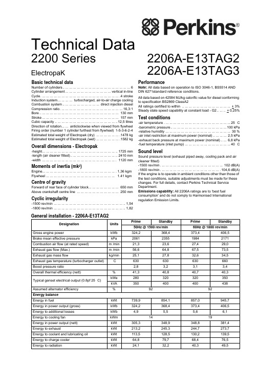
Technical DataBasic technical dataNumber of cylinders.. ... ... ... ... ... ... ... ... ... ... ... ... ... ... ... ... ...6 Cylinder arrangement... ... ... ... ... ... ... ... ... ... ... ...vertical in-line Cycle. ... ... ... ... ... ... ... ... ... ... ... ... ... ... ... ... ... ... ... ... .4 stroke Induction system... ... ... ... turbocharged, air-to-air charge cooling Combustion system.. ... ... ... ... ... ... ... ... ... direct injection diesel Compression ratio. ... ... ... ... ... ... ... ... ... ... ... ... ... ... ... ...16,3:1Bore.. ... ... ... ... ... ... ... ... ... ... ... ... ... ... ... ... ... ... ... ... 130 mm Stroke ... ... ... ... ... ... ... ... ... ... ... ... ... ... ... ... ... ... ... ... 157 mm Cubic capacity .. ... ... ... ... ... ... ... ... ... ... ... ... ... ... ... ..12,5 litres Direction of rotation... ... anticlockwise when viewed from flywheel Firing order (number 1 cylinder furthest from flywheel)1-5-3-6-2-4Estimated total weight of Electropak (dry) ... ... ... ... ... ... .1478 kg Estimated total weight of Electropak (wet) ... ... ... ... ... ... .1582 kgOverall dimensions - Electropak-height... ... ... ... ... ... ... ... ... ... ... ... ... ... ... ... ... ... ... ..1725 mm -length (air cleaner fitted).. ... ... ... ... ... ... ... ... ... ... ... ..2410 mm -width ... ... ... ... ... ... ... ... ... ... ... ... ... ... ... ... ... ... ... . 1120 mmMoments of inertia (mk²)Engine... ... ... ... ... ... ... ... ... ... ... ... ... ... ... ... ... ... ... .1,36 kgm²Flywheel ... ... ... ... ... ... ... ... ... ... ... ... ... ... ... ... ... ... 1.41 kgm²Centre of gravityForward of rear face of cylinder block... ... ... ... ... ... ... ... 650 mm Above crankshaft centre line ... ... ... ... ... ... ... ... ... ... ... 250 mmCyclic irregularity-1500 rev/min ... ... ... ... ... ... ... ... ... ... ... ... ... ... ... ... ... ... ..1,54-1800 rev/min ... ... ... ... ... ... ... ... ... ... ... ... ... ... ... ... ... ... ..1,82PerformanceNote:All data based on operation to ISO 3046-1, BS5514 AND DIN 6271standard reference conditions.All data based on 42584 MJ/kg calorific value for diesel conforming to specification BS2869 ClassA2All ratings certified to within .. ... ... ... ... ... ... ... ... ... ... ... ... + 3%Steady state speed capability at constant load - G2.. ... .. + 0,25%Test conditions-air temperature . ... ... ... ... ... ... ... ... ... ... ... ... ... ... ... ... ...25 °C -barometric pressure.. ... ... ... ... ... ... ... ... ... ... ... ... ... ...100 kPa -relative humidity ... ... ... ... ... ... ... ... ... ... ... ... ... ... ... ... ... 30 %-air inlet restriction at maximum power (nominal).. ... ... ... 2,5 kPa -exhaust back pressure at maximum power (nominal).. ... 6,8 kPa -fuel temperature (inlet pump) ... ... ... ... ... ... ... ... ... ... ... ...40 °CSound levelSound pressure level (exhaust piped away, cooling pack and air cleaner fitted)-1500 rev/min. ... ... ... ... ... ... ... ... ... ... ... ... ... ... ... ... 102 dB(A)-1800 rev/min. ... ... ... ... ... ... ... ... ... ... ... ... ... ... ... .104,6 dB(A)If the engine is to operate in ambient conditions other than those of the test conditions, suitable adjustments must be made for these changes. For full details, contact Perkins Technical Service Department.Emissions capability: All 2206A ratings are to ‘best fuel consumption’ and do not comply to Harmonised International regulation Emission Limits.General installation DesignationUnits Prime Standby Prime Standby 50Hz @ 1500 rev/min60Hz @ 1800 rev/minGross engine powerkWb 324,2368,4373,4406,5Brake mean effective pressure kPa 2061235519842171Combustion air flow (at rated speed)m³/min 21,323,627,429,0Exhaust gas flow (Max.)m³/min 56,664,867,573,5Exhaust gas mass flowkg/min 25,127,832,634,5Exhaust gas temperature (turbocharger outlet)°C630630630660Boost pressure ratio2,83,23,13,4Overall thermal efficiency (nett)%41,340,840,740,3Typical genset electrical output (0.8pf 25 °C)kWe 280320320350kVA 350400400438Assumed alternator efficiency %9292Energy balance Energy in fuelkWt 739,9854,1857,0945,7Energy in power output (gross)kWb 324,2368,4373,4406,5Energy to additional losses kWb 4,95,55,66,1Energy to cooling fan kWm 1419Energy in power output (nett)kWt 305,3348,9348,8381,4Energy to exhaustkWt 213,2245,3244,7273,7Energy to coolant and lubricating oil kWt 113,5128,5130,2139,5Energy to charge cooler kWt 64,879,768,476,5Energy to radiationkWt24,132,240,349,5 - 2206A-E13TAG22200 Series2206A-E13TAG2 2206A-E13TAG3ElectropaKGeneral installationDesignation Units Prime Standby Prime Standby50Hz @ 1500 rev/min60Hz @ 1800 rev/min Gross engine power kWb368,4412,5373,4406,5 Brake mean effective pressure kPa2344263719842171 Combustion air flow (at rated speed)m³/min24,326,427,429,0 Exhaust gas flow (Max.)m³/min64,672,567,573,5 Exhaust gas mass flow kg/min28,130,932,634,5 Exhaust gas temperature (turbocharger outlet)°C630630660660 Boost pressure ratio3,23,53,13,4 Overall thermal efficiency (nett)%41,440,940,740,3Typical genset electrical output (0.8pf 25 °C)kWe320360320350 kVA400450400438Assumed alternator efficiency%9292Energy balanceEnergy in fuel kWt842,6958,2857,0945,7 Energy in power output (gross)kWb368,4412,5373,4406,5 Energy to additional losses kWb5,56,25,66,1 Energy to cooling fan kWm1419Energy in power output (nett)kWt348,9392,3348,8381,4 Energy to exhaust kWt252,6290,4244,7273,7 Energy to coolant and lubricating oil kWt127,3139,9130,2139,5 Energy to charge cooler kWt60,375,568,476,5 Energy to radiation kWt34,039,840,349,6 - 2206A-E13TAG3Rating definitionsPrime powerVariable load. Unlimited hours usage with an average load factor of 70% of the published Prime Power rating over each 24 hour period.A 10% overload is available for 1 hour in every 12 hours of operationStandby powerVariable load. Limited to 500 hours annual usage up to 300 hours of which may be continuous running, No overload is permittedCooling systemRadiatorFace area . ... ... ... ... ... ... ... ... ... ... ... ... ... ... ... ... ... ...1,238 m²Number of rows and materials . ... ... ... ... ... ... .1rows, aluminium Matrix density and material .. ... ... ... ..12 fins per inch, aluminium Width of matrix . ... ... ... ... ... ... ... ... ... ... ... ... ... ... ... . 1048 mm Height of matrix ... ... ... ... ... ... ... ... ... ... ... ... ... ... ... . 1100 mm Weight of radiator (dry). ... ... ... ... ... ... ... ... ... ... ... ... ... ..132 kg Pressure cap setting (min) ... ... ... ... ... ... ... ... ... ... ... ... ..70 kPa Charge coolerFace area.. ... ... ... ... ... ... ... ... ... ... ... ... ... ... ... ... ... ...1,006 m²Number of rows and materials . ... ... ... ... ... ... .1rows, aluminium Matrix density and material .. ... ... ... ..12 fins per inch, aluminium Width of matrix . ... ... ... ... ... ... ... ... ... ... ... ... ... ... ... ... 915 mm Height of matrix ... ... ... ... ... ... ... ... ... ... ... ... ... ... ... . 1100 mm Coolant pumpSpeed @ 1500 rev/min. ... ... ... ... ... ... ... ... ... ... ... 2056 rev/min Speed @ 1800 rev/min. ... ... ... ... ... ... ... ... ... ... ... 2468 rev/min Drive method. ... ... ... ... ... ... ... ... ... ... ... ... ... ... ... ... ... ... .Gear FanDiameter ... ... ... ... ... ... ... ... ... ... ... ... ... ... ... ... ... ... ... 927 mm Drive ratio.. ... ... ... ... ... ... ... ... ... ... ... ... ... ... ... ... ... ... ...0,92:1 Number of blades.. ... ... ... ... ... ... ... ... ... ... ... ... ... ... ... ... ... .. 9 Material. ... ... ... ... ... ... ... ... ... ... ... ... ... ... ... ... ... ... .composite Type.. ... ... ... ... ... ... ... ... ... ... ... ... ... ... ... ... ... ... ... ... . pusher Cooling fan air flow @ 1500 rev/min. ... ... ... ... ... ... ...654 m³/min Cooling fan air flow @ 1800 rev/min. ... ... ... ... ... ... ...788 m³/min CoolantTotal system capacity ... ... ... ... ... ... ... ... ... ... ... ... ... . 51,4 litres Max. top tank temperature ... ... ... ... ... ... ... ... ... ... ... ... ..104 °C Temperature rise across engine... ... ... ... ... ... ... ... ... ... ... 10 °C Max. pressure in engine cooling circuit. ... ... ... ... ... ... ... ..70 kPa Max. permissible external system resistance ... ... ... ... ... ..30 kPa Max. static pressure head on pump.. ... ... ... ... ... ... ... ... ..30 kPa Coolant flow (min) against 30 kPa rstriction@ 1500 rev/min. ... ... ... ... ... ... ... ... ... ... ... ... ... ... .5,3 litres/sec @ 1800 rev/min. ... ... ... ... ... ... ... ... ... ... ... ... ... ... .6,7 litres/sec Thermostat operation range.. ... ... ... ... ... ... ... ... ... ... 87 to 98°C For details of recommended coolant specifications, refer to the Operation and Maintenance Manual for this engine model Duct allowanceDuct allowance 2206A-E13TAG2 - standbyMaximum additional retsriction (duct allowance) to cooling airflow and resultant minimum airflowEngine speedrev/minAmbient clear-ance inhibitedcoolant °CDuctallowancePam³/min 150059200563180059200716Duct allowance 2206A-E13TAG3 - standbyMaximum additional retsriction (duct allowance) to cooling airflow and resultant minimum airflowEngine speedrev/minAmbient clear-ance inhibitedcoolant °CDuctallowancePam³/min 150055200563180059200716Electrical system-type... ... ... ... ... ... ... ... ... ... ... ... ... ... ... .24 Volt negative earth Alternator type ... ... ... ... ... ... ... ... ... ... ... ... ... ... ... ... ... ... .22SI -alternator voltage.. ... ... ... ... ... ... ... ... ... ... ... ... ... ... ... ... ..24V -alternator output ... ... ... ... ... ... ... ... ... ... ... ... ... ... ... ... ... ..70A Starter motor type.. ... ... ... ... ... ... ... ... ... ... ... ... ... ... ... ...39MT -starter motor voltage. ... ... ... ... ... ... ... ... ... ... ... ... ... ... ... ..24V -starter motor power... ... ... ... ... ... ... ... ... ... ... ... ... ... ... .7,8 kW Number of teeth on flywheel.. ... ... ... ... ... ... ... ... ... ... ... ... ..113 Number of teeth on starter pinion.. ... ... ... ... ... ... ... ... ... ... (11)Minimum cranking speed... ... ... ... ... ... ... ... ... ... ... 106 rev/min Starter solenoid maximum-pull-in current @ 0°C ... ... ... ... ... ... ... ... ... ... ... ... ... ... ... 200A -hold-in current @ 0°C... ... ... ... ... ... ... ... ... ... ... ... ... ... ... ..25A Cold start recommendations-5°C to -10°Coil... ... ... ... ... ... ... ... ... ... ... ... ... ... ... ... ... ..SAE grade 15W40 Starter ... ... ... ... ... ... ... ... ... ... ... ... ... ... ... ... ... ... ... ... ...42MT Battery ... ... ... ... ... ... ... ... ... ... ... ... ... ... ... ... ... ... ... ... 24 volts Max. breakaway current. ... ... ... ... ... ... ... ... ... ... ... ..1311 amps Cranking current ... ... ... ... ... ... ... ... ... ... ... ... ... ... ... 588 amps Starting aids (ECM controlled)... ... ... ... ... ... ... ... ... ... ... ... none Min. mean cranking speed. ... ... ... ... ... ... ... ... ... ... .106 rev/min -11°C to -25°Coil... ... ... ... ... ... ... ... ... ... ... ... ... ... ... ... ... ... SAE grade 5W40 Starter ... ... ... ... ... ... ... ... ... ... ... ... ... ... ... ... ... ... ... ... ...42MT Battery ... ... ... ... ... ... ... ... ... ... ... ... ... ... ... ... ... ... ... ... 24 volts Max. breakaway current. ... ... ... ... ... ... ... ... ... ... ... ..1585 amps Cranking current ... ... ... ... ... ... ... ... ... ... ... ... ... ... ... 828 amps Starting aids (ECM controlled)... block heater 1,5kW (110V/240V) Min. mean cranking speed. ... ... ... ... ... ... ... ... ... ... .106 rev/min Notes:z Battery capacity is defined by the 20 hour ratez The oil specification should be for the minimum ambient temperature as the oil will not be warmed by the immersion heaterz Breakaway current is dependent on the battery capacity available. Cables should capable of handling transient current twice that of cranking current.Exhaust systemMaximum back pressure-1800 rev/min . ... ... ... ... ... ... ... ... ... ... ... ... ... ... ... ... .10,0 kPa Exhaust outlet, internal diameter. ... ... ... ... ... ... ... ... ... . 123 mm Fuel systemInjection system... ... ... ... ... ... ... ... ... ... ... ... ... ... ... ... ... ..MEUI Injector type. ... ... ... ... ... ... ... ... ... ... ... ... ... ... ... ... ... ... ..MEUI Governor type.. ... ... ... ... ... ... ... ... ... ... ... ... ... ... ... ... electronic Governing conforms to ... ... ... ... ... ... ... ... .ISO 8528-5 Class G2 Injector pressure.. ... ... ... ... ... ... ... ... ... ... ... ... ... ... ... .207 MPa Fuel lift pump-lift pump type.. ... ... ... ... ... ... ... ... ... ... ... ... ... ... ... .gear driven -lift pump delivery @1500 rev/min... ... ... ... ... ... ... 480 litres/hour -lift pump delivery @1800 rev/min... ... ... ... ... ... ... 600 litres/hour -lift pump delivery pressure. ... ... ... ... ... ... ... ... ... ... ... ..621 kPa -max. suction head at pump inlet ... ... ... ... ... ... ... ... ... ... ... .3 m -max. static pressure head.. ... ... ... ... ... ... ... ... ... ... ... ... ... .4 m -max. fuel inlet temperature. ... ... ... ... ... ... ... ... ... ... ... ... ..55 °C -fuel filter spacing primary... ... ... ... ... ... ... ... ... ... ... .10 microns -fuel filter spacing secondary... ... ... ... ... ... ... ... ... ... ...2 microns Fuel specificationBS2869 Class A2 or BSEN590ASTM D975 Class 1D and class 2DNote:For further information on fuel specifications and restrictions, refer to the OMM, “Fluid Recommendations” for this engine model. Induction systemMaximum air intake restriction-clean filter... ... ... ... ... ... ... ... ... ... ... ... ... ... ... ... ... ... ...2,5 kPa -dirty filter. ... ... ... ... ... ... ... ... ... ... ... ... ... ... ... ... ... ... ...6,4 kPa -air filter type ... ... ... ... ... ... ... . paper element - 15 inch diameterLubrication systemMaximum total system oil capacity ... ... ... ... ... ... ... ... ... .40 litres Minimum oil capacity in sump... ... ... ... ... ... ... ... ... ... ..32,5 litres Maximum oil capacity in sump.. ... ... ... ... ... ... ... ... ... ... .38 litres Maximum engine operating angles -front up, front down, right side, left side ... ... ... ... ... ... ... ... ... 7 °Lubricating oil-oil flow @ 1500 rev/min... ... ... ... ... ... ... ... ... ... ... 140 litres/min -oil flow @ 1800 rev/min... ... ... ... ... ... ... ... ... ... ... 172 litres/min -oil pressure at bearings @ 1500 rev/min. ... ... ... ... ... ... 310 kPa -oil pressure at bearings @ 1800 rev/min. ... ... ... ... ... ... 358 kPa -oil pressure at bearings (min).. ... ... ... ... ... ... ... ... ... ... 270 kPa -oil temperature (continuous operation) ... ... ... ... ... ... ... ..113 °C -oil consumption at full load as a % of fuel consumption.. ...0.15% Oil filter screen spacing. ... ... ... ... ... ... ... ... ... ... ... ... 30 microns Oil consumption as % of fuel consumption... ... ... ... ... ... ... ... 0,1 Sump drain plug tapping... ... ... ... ... ... ... ... ... ... ... ... .1 1/8 UNF Lubricating oil specification... ... ... ... ... ... API-CH4 - SAE15W-40 Recommended SAE viscosityEngine Oil ViscosityEMA LRG-1API CH-4 Viscosity GradeAmbient Temperature Minimum MaximumSAE 0W20-40 °C10 °CSAE 0W30-40 °C30 °CSAE 0W40-40 °C40 °CSAE 5W30-30 °C30 °CSAE 5W40-30 °C40 °CSAE 10W30-20 °C40 °CSAE 15W40-10 °C50 °C MountingsMaximum static bending moment at rear face of block. ...1356 Nm Fuel consumption2206A-E13TAG2 - 1500 rev/minLoad g/kWhr l/hr Standby19580 110% Prime power19577 100% Prime power19671 75% of Prime power19854 50% of Prime power203372206A-E13TAG3 - 1500 rev/minLoad g/kWhr l/hr Standby19490 110% Prime power19689 100% Prime power19781 75% of Prime power19962 50% of Prime power202422206A-E13TAG2 - 1800 rev/minLoad g/kWhr l/hr Standby19387 110% Prime power19588 100% Prime power19681 75% of Prime power19962 50% of Prime power205432206A-E13TAG3 - 1800 rev/minLoad g/kWhr l/hr Standby19387 110% Prime power19588 100% Prime power19681 75% of Prime power19962 50% of Prime power20543All fuel consumption figures are based on Nett powerAll information in the document is substantially correct at the time of printing but may be subsequently altered by the company.Distributed by2200 Series2206A-E13TAG22206A-E13TAG3Load acceptance TAG2 (cold) Initial load application: When engine reaches rated speed(15 seconds maximum after engine starts to crank)DescriptorUnits 50 Hz 60Hz % of prime power %6680Load (nett)kWm 184,8256Transient frequency deviation%<10<10Frequency recoverySeconds55Second load application: When engine reaches rated speed(5 seconds after initial load application)DescriptorUnits 50 Hz 60Hz % of prime power %7385Load (nett)kWm 204,4272Transient frequency deviation%<10<10Frequency recoverySeconds55TAG3 (cold) Initial load application: When engine reaches rated speed(15 seconds maximum after engine starts to crank)DescriptorUnits 50 Hz 60Hz % of prime power %5880Load (nett)kWm 185,6256Transient frequency deviation%<10<10Frequency recoverySeconds55Second load application: When engine reaches rated speed(5 seconds after initial load application)DescriptorUnits 50 Hz 60Hz % of prime power %6585Load (nett)kWm 208272Transient frequency deviation%<10<10Frequency recoverySeconds55The information shown above complies with the requirements of classification 3 and 4 of ISO 8528-12 and G2 operating limits stated in ISO 8528-5The above figures were obtained under the following test conditions:-minimum engine block temperature.. ... ... ... ... ... ... ... ... ... ... ... ... ... ... ... ... ... ... ... ... ... ... ... ... ... ... ... ... ... ... ... ... ... ... ... ... . 45 °C -ambient temperature. ... ... ... ... ... ... ... ... ... ... ... ... ... ... ... ... ... ... ... ... ... ... ... ... ... ... ... ... ... ... ... ... ... ... ... ... ... ... ... ... ... ... ..15 °C -governing mode ... ... ... ... ... ... ... ... ... ... ... ... ... ... ... ... ... ... ... ... ... ... ... ... ... ... ... ... ... ... ... ... ... ... ... ... ... ... ... ... ... ... isochronous -alternator efficiency... ... ... ... ... ... ... ... ... ... ... ... ... ... ... ... ... ... ... ... ... ... ... ... ... ... ... ... ... ... ... ... ... ... ... ... ... ... ... ... ... ... ... ... 92%-alternator inertia ... ... ... ... ... ... ... ... ... ... ... ... ... ... ... ... ... ... ... ... ... ... ... ... ... ... ... ... ... ... ... ... ... ... ... ... ... ... ... ... ... ... ... 6,9 kgm²-under frequency roll off (UFRO) point set to. ... ... ... ... ... ... ... ... ... ... ... ... ... ... ... ... ... ... ... ... ... ... ... ... ... ... ... ... ... 1 Hz below rated -UFRO rate set to... ... ... ... ... ... ... ... ... ... ... ... ... ... ... ... ... ... ... ... ... ... ... ... ... ... ... ... ... ... ... ... ... ... ... ... 2% voltage / 1% frequency LAM on/off.. ... ... ... ... ... ... ... ... ... ... ... ... ... ... ... ... ... ... ... ... ... ... ... ... ... ... ... ... ... ... ... ... ... ... ... ... ... ... ... ... ... ... ... ... ... ... ... ...off All tests were conducted using an engine which was installed and serviced to Perkins Engines Company Limited recommendations.Note:The general arrangement drawings shown in this data sheet are for guidance only. For installation purposes, latest versions should be requested from the Applications Dept., Perkins Engines Stafford, ST16 3UB United Kingdom.P u b l i c a t i o n N o . T P D 1687E 2. O c t o b e r 2008 P e r k i n s E n g i n e s C o m p a n y L i m i t e dPerkins Engines Company LimitedPeterborough PE1 5NA United Kingdom Telephone +44 (0) 1733 583000Fax +44 (0) 1733 。
ZB-TFQ12 迪欧空调吸尘器维护手册说明书

Installation and Maintenance ManualCompact Vacuum UnitSeries ZBThis manual contains essential information for the protection of users andothers from possible injury and/or equipment damage.∙Read this manual before using the product, to ensure correct handling,and read the manuals of related apparatus before use.∙Keep this manual in a safe place for future reference.∙ These instructions indicate the level of potential hazard by label of“Caution”, “Warning” or “Danger”, followed by important safety informationwhich must be carefully followed.∙To ensure safety of personnel and equipment the safety instructions inthis manual and the product catalogue must be observed, along with otherrelevant safety practices.CautionIndicates a hazard with a low level of risk, which ifnot avoided, could result in minor or moderateinjury.WarningIndicates a hazard with a medium level of risk,which if not avoided, could result in death orserious injury.DangerIndicates a hazard with a high level of risk, whichif not avoided, will result in death or seriousinjury.∙ The compatibility of pneumatic equipment is the responsibility of theperson who designs the pneumatic system or decides its specifications.Since the products specified here can be used in various operatingconditions, their compatibility with the specific pneumatic system must bebased on specifications or after analysis and/or tests to meet specificrequirements.∙Only trained personnel should operate pneumatically operatedmachinery and equipment.Compressed air can be dangerous if an operator is unfamiliar with it.Assembly, handling or repair of pneumatic systems should be performedby trained and experienced personnel.∙Do not service machinery/equipment or attempt to removecomponents until safety is confirmed.1) Inspection and maintenance of machinery/equipment should only beperformed after confirmation of safe locked-out control positions.2) When equipment is to be removed, confirm the safety process asmentioned above. Switch off air and electrical supplies and exhaust allresidual compressed air in the system.3) Before machinery/equipment is re-started, ensure all safety measuresto prevent sudden movement of cylinders etc. (Supply air into the systemgradually to create back pressure, i.e. incorporate a soft-start valve).∙Do not use this product outside of the specifications. Contact SMCif it is to be used in any of the following conditions:1) Conditions and environments beyond the given specifications, or if theproduct is to be used outdoors.2) Installations in conjunction with atomic energy, railway, air navigation,vehicles, medical equipment, food and beverage, recreation equipment,emergency stop circuits, press applications, or safety equipment.3) An application which has the possibility of having negative effects onpeople, property, or animals, requiring special safety analysis.∙Ensure that the air supply system is filtered to 5 microns.2 SpecificationsRefer to the operation manual for this product.3 Installation3.1 Installation∙Do not install the product unless the safety instructions have been readand understood.Note the following points when mounting and installing the product.■ Common Precautions for Mounting and Installation1) It is necessary to perform maintenance and replacement of the suctionfilter regularly to maintain the proper operation of the ejector and vacuumpump system. Ensure sufficient space for maintenance work wheninstalling the product.2) The filter case of this product is integrated with the vacuum piping.Secure sufficient space and some length of the tube with the piping(tubes) on the vacuum side so that the case can be removed.3) Do not fix the piping on the vacuum side such that a load is alwaysapplied to the filter case in a bending or pulling direction. This candamage the body and/or the filter case.4) If the ejector (silencer exhaust specification) is operated in a dustyenvironment or if there is dust on the surface of the workpieces, it cancause clogging of the silencing material as well as the suction filter dueto dust being sucked in. Secure space necessary for the maintenancecheck and replacement of the silencer when the ejector performancedecreases.5) Keep the ambient temperature of the product between -5 and 50o C. Inenvironments such as inside a panel where heat radiation efficiency ispoor, the ambient temperature will rise due to the heat generation of thecoil of the solenoid valve, causing malfunction.6) When handling the product, do not lift it by the lead wires or cables ofthe solenoid valve, pressure sensor or pressure switch for vacuum.Otherwise, it can cause vacuum leakage or broken wire or damage tothe product.■Mounting and Installation of Single Unit Ejectors1) The tightening torque for mounting the product to the wall should bebetween 0.075 and 0.096Nm. Using excessive torque may causedamage to the body. (The width of the product is 10mm.)2) Do not block the exhaust port of the ejector. The ejector of the singleunit specification has only one exhaust port on one side. If the ejector ismounted with the exhaust port facing a wall, secure a space of at least1mm between the product and the wall using a spacer, shim orequivalent.(3) Secure the space for connecting piping on the supply side wheninstalling the product.Mounting with a bracket for single unit (Width of the bracket: 1mm)3 Installation (cont.)Mounting on the wall and the port released to the atmosphere at the bottomPart No. of the bracket for single unit: ZB1-BK1-A (Provided with 2mounting screws M2x14 with washer and 2 hexagon nuts M2.)Recommended tube fittings for the set-up shown above: KQ2H04-M5N,KQ2L04-M5N, KQ2W04-M5N.■Mounting and Installation of an Ejector of Manifold SpecificationWhen mounting the manifold base, it is recommended to mount a spaceron the filter case side in order to make it easier to perform maintenanceservice of the filter element. (Width of the manifold base mounting hole:11.6mm)3.2 Environment∙Do not use in an environment where corrosive gases, chemicals, saltwater or steam are present.∙Do not use in an explosive atmosphere.∙Do not expose to direct sunlight. Use a suitable protective cover.∙Do not install in a location subject to vibration or impact. Check the productspecifications.∙Do not mount in a location exposed to radiant heat.3.3 Piping■Piping for Air Pressure Supply and Vacuum Pressure Supply1) Preparation before pipingBefore piping, perform air blow (flushing) or cleaning to remove anycutting chips, cutting oil, dust, etc. from the piping.2) Wrapping of pipe tapeWhen installing piping or a tube fitting into a port, prevent cuttingchips and sealant material from getting inside the product.If a sealant tape is used,leave 1 thread exposedat the end of threads.3) When connecting tubing, consider factors such as changes in thetubing length due to pressure, and allow a sufficient margin.Otherwise, it can damage the fitting and cause the tube to come off.Refer to Fittings & Tubing Precautions from 1 to 4 shown in BestPneumatics 6 on SMC’s website (URL ) forthe recommended piping conditions.3 Installation (cont.)■Piping to the Manifold Base1) For the PV port of the manifold base, use a tube fitting whose maximumbore size of the outside dimension is smaller than 12mm.Otherwise, the exterior of the fitting will interfere with the manifold baseinstallation face.Recommended tube fittings:KQ2S06-01□S, KQ2S04-01□S2) Follow the tightening instructions shown below for each thread.1/8 (PV port) : 7 to 9NmTightening torque is 3 to 5N as a guide.M5 (PV, PD port): After tightening by hand, increase the tightening byabout 1/6 turn with a tightening tool.Tightening torque is 1 to 1.5N as a guide.3) When mounting or removing the tube fitting,etc. to the manifold base,hold the manifold base hold the manifold base with a spanner.If the ejector/vacuum pump system is held, it may cause air leakage ordamage to the product.■Piping to the Vacuum (V) Port1) Allow a sufficient margin of tube length when piping, in order to preventtwisting, tensile, moment loads, vibration or impact being applied to thetubes and fittings.This can cause damage to the tube fittings and crushing, bursting ordisconnection of tubing.2) Piping to the product is assumed to be static piping.If the tube moves, it may become worn, elongated or torn due to tensileforces, or disconnected from the fitting. Ensure the tube is in a staticcondition at all times before using.3) Prevent the connected tube from being rotated.If the fittings are used in this way, the fitting may be broken.4) Do not lift the product by holding the piping after the tube is connected tothe vacuum (V) port.Otherwise, the filter case and/or the One-touch tube fitting will bedamaged.4 Settings■Manual OverrideVacuum for the ejector or the vacuum pump system is generated orreleased by manual operation.Use the manual override after confirming that there is no danger.When operating the locking type with a screwdriver, turn it gently using awatchmaker’s screwdriver. (Torque: Less than 0.1Nm)Sealant tapeLeave 1 threadexposed.Wrap this way.Non-locking push type (Tool required)It is turned ON by pressing the manual override allthe way in the direction indicated by the arrow (↓),and it is turned OFF by releasing it.11.65 Maintenance■Construction of ZB seriesManifold / With pressure sensorSingle unit / With vacuum pressure switch■ComponentsThe components from (7) to (15) are available as service parts.■Implement the maintenance and check shown below in order to use the ejector and the vacuum system safely and in an appropriate way for a long period of time.1) Maintenance should be performed according to the procedure indicated in the Operation Manual.Improper handling can cause damage and malfunction of equipment and machinery.2) Maintenance workCompressed air can be dangerous when handled incorrectly. Therefore, in addition to observing the product specifications, replacement of elements and other maintenance activities should be performed by personnel with sufficient knowledge and experience pertaining to pneumatic equipment. 3) DrainingRemove condensate from air filters and mist separators regularly. If the collected drainage is drained to the downstream side, it can stick inside of the product, causing operation failure and failure to reach the specified vacuum pressure.4) Replace the filter element built into the ejector and the vacuum pump system and the silencer regularly. (Refer to the replacement procedure below.)It is recommended to replace the filter element and the silencer when the pressure drop reaches 5kPa as a guideline. The replacement cycle varies depending on the operating conditions, operating environment and supply air quality.However, if there is a vacuum pressure drop and/or delay in the vacuum (adsorption) response time which causes problem with the settings during operation, stop the operation of the product and replace the element regardless of the above mentioned replacement guideline. 5) Operation in an environment where there is a lot of dust in the airThe processing capacity of the filter element built into the product may be insufficient. It is recommended to use SMC's air suction filter (ZFA, ZFB, ZFC series) in order to avoid problems beforehand. 6) Check before and after the maintenance workWhen the product is to be removed, turn off the power supply, and be sure to cut off the supply pressure and exhaust the compressed air. Confirm that the air is released to atmosphere.When mounting the product after the maintenance work, supplycompressed air, connect to the power, check if it functions properly and have a leakage inspection. Especially for the latching type supply valve, be sure to check that the supply valve is OFF in the initial condition because it is possible that it is ON due to vibration.7) Do not disassemble or modify the product, other than the replacement parts specified in this manual.■Spare parts listNo. Description [Application]ModelRemarks (7) Supply valve[Generates vacuum.] ZB1-VQ110U-□□□ N.C. ZB1-VQ110L-□□□ Latching ZB1-VQ120U-□□□ N.C. (8) Release valve [Releases vacuum] ZB1-VQ110-□□□ N.C. (9) V-port Assembly [For vacuum port]ZB1-VPN3-□-A (10)Exchange the One-touch tube fittings with the port plugs KJ □□-C1(11)Filter element[For suction filter]ZB1-FE3-A(12) Silencer [For silencer] ZB1-SE1-A (13) Pressure sensor assemblyZB1-PS □-A (14)Pressure switch assembly forvacuumZB1-ZS □□□□-A(15) Manifold base assemblyZZB □-□□□ ■Replacement Procedure for Filter Element- Hold the V port assembly with your fingers, and turn it45 degrees in the counter-clockwise direction and pull it out.For the straight type One-touch tube fitting, it can be removed by using a hexagon wrench (width across flats: 2).- Remove the filter element from the removed filter case, and mount a new filter element securely to the back of the case. (See Fig. to the right) - Confirm that the filter case gasket is not displaced and that it has no foreign matter stuck to it.- Insert the V port assembly into the ejector/vacuum pump system (Fig. to the right), press it slightly and turn it for approximately 45 degrees in the clockwise direction until it stops. (See Fig. to the right)(Mount the V port assembly in the direction specified in the figure. If the convex side is mounted downward, it will interfere with the floor when the element is mounted on its bottom surface, causing breakage of the filter case and the element.)■Replacement procedure for silencer*- Turn the body upside down. Apply a watchmaker’s screw driver or your finger to the notch, and slide the silencer cover in the direction indicated by the △ mark.- When it clicks, the hook is disconnected. Put your Pry up and remove part A, cover.- Remove the silencer by using a watchmaker’s screw driver.- Insert a new silencer, and mount the cover by the reverse procedure of the disassembly procedure for reassembly.(When replacing the silencer, the metal diffuser can be seen. This part is important to the function. Do not touch or apply force to the metal diffuser when replacing the silencer.)* For vacuum pump system, the silencer is not built in.■Replacement Procedure for Solenoid Valves (supply valve, release valve)-This product has a “supply valve” for generating vacuum and a “release valve” for breaking vacuum. Follow the procedure below to replace the solenoid valves after the product has been used for a long period of time or malfunctions.1) Remove the mounting screw of the solenoid valve. 2) Remove the solenoid valve.3) Before mounting the replacement solenoid valve, check that it has no dust or scratches on the mounting surface. Be certain that the gasket and filter element R of the supply valve are properly mounted as well. (Filter element R is installed in the release valve only.)4) Tighten the mounting screw of the solenoid valve to the specified torque below.Appropriate tightening torque (Nm) 0.054 to 0.08- When replacing the solenoid valves, the valve body will come off if boththe supply valve and the release valve are removed at the same time.Removal and mounting of the solenoid valves should be done one at atime to prevent parts from dropping and foreign matter from entering.* Function of the filter element R: When the supply valve is switched OFF from ON, atmospheric pressure flows from the vent port into the spaceinside the valve where there is “vacuum pressure”. Filter element R is afilter mounted in the flow path. It prevents the dust in the operating environment from entering inside the solenoid valve.Manifold Products■Increasing and Decreasing the Number of Manifold Stations- When decreasing the number of manifold stations, order the manifoldbase (a) exclusive for the required number of stations. When increasing the number of stations, order the required number of single units of the body type 3 valve (b). Refer to Model Indication and How to Order for the part numbers for placing an order. The part number for the manifold base is different depending on whether pressure sensor/ vacuum pressure switch are mountable or not.- When mounting each station, check that all the gaskets are in place and tighten the screws to the specified torque. If the tightening torque is exceeded, the body can be broken.- For the manifold with pressure sensor/vacuum pressure switch, order themanifold base (a) for the required number of stations. When increasing the number of stations, order the required number of single unit of the body type 3 valve (b) and the required number of either the pressure sensor assembly (c) or the vacuum pressures switch assembly (d).- In this case, the pressure sensor (c) /vacuum pressure switch (d) is tightened together with the single unit of the product (b). (Refer to the figure on the right.)- When mounting the pressure sensor/ vacuum pressure switch, be sure to check that the O-ring on the mounting surface of the manifold base is mounted properly and that the O-ring is not displaced from the mounting groove. If the O-ring is not mounted properly, it can cause vacuum pressure leakage.Locking push type (Tool required) <Latching type> - Turn the manual override to the left and line up the arrow () with 0 to return it to the RESET state (flow from A toP). (It is set to RESET state when shipped.)SET RESETNo. Item Main partsmaterial Remarks(1) Valve bodyassembly Resin/HNBR Solenoid valve mounting part(2) Needle assembly Resin/ Brass/ NBR For adjusting release flow, with lock nut retaining mechanism(3) Body ResinBodies for ejector and for pump system both available. (4)Nozzle Aluminum For vacuum pump system: Spacer (5) Diffuser AluminumFor vacuum pump system: No diffuser(6) Silencer cover Resin △ markSilencer coverConcave Part A SilencerMounting screw Valve bodySupply valve Filter element R *)Gasket Gasket(a)Appropriate tighteningtorque (Nm) 0.075 to 0.096(b)(a) (b)(d) (c) Vacuum pressure release port (Pressure sensor/vacuum pressureswitch can be mounted)Locking type (Tool required) <Semi-standard>- Turn the manual override to the left and line up () manual override.Note) For the locking type manual override, be sure to release the lock before starting the normal operation.Filter case■Special transparent filter case made of nylonDo not use in an environment where chemicals such as alcohol are present and where they could stick to the filter case.Vacuum Break Flow Adjusting Needle ■Vacuum break flow characteristicsThe graph on the right shows the flow characteristics with various supply pressures when the vacuum break flow adjustment needle is opened from the fully close state “n” turns.However, the flow characteristics shown in this graph are represent values of the single unit of the product.The flow at the absorption part may vary depending on the piping conditions to the vacuum (V) port, circuit etc.The flow characteristics and the number of rotations of the needle vary due to the range of the specifications of the product.■ This product has a needle retaining mechanism.The needle stops rotating when it reaches the rotation stop position. It may damage the product if the needle is rotated past its stop position. ■Do not tighten the needle any more after it reaches the fully closed position (fully Clockwise).The fully closed position is when the end of the needle touches the resin hole. If it is tightened any more after the needle reaches the position where it stops, the resin part will be deformed, causing breakage. ■Do not tighten the handle with tools such as pliers. This can result in breakage due to idle turning.Exhaust from Ejector■Avoid back pressure being applied to the exhaust air of the ejector. The exhaust resistance should be as small as possible to obtain the full ejector performance.There should be no shield around the exhaust port for the silencer exhaust specification. For the port exhaust specification, the back pressureincrease should be 0.005MPa (5kPa) at maximum, as exhaust resistance is generated with some piping bore sizes and piping lengths. For tube ID 4, as a guideline, it is recommended to make the piping length 1000mm at maximum, although it varies depending on the condition of the equipment at the end.For the silencer exhaust specification, the silencer will gradually getclogged if dust in the operating environment is sucked in or if the supply air is not clean enough. If the silencer is clogged, back pressure is applied to the ejector exhaust which results in a reduction in the vacuum pressure and the adsorption flow rate.7 ContactsAUSTRIA (43) 2262 62280-0 LATVIA(371) 781 77 00 BELGIUM (32) 3 355 1464 LITHUANIA(370) 5 264 8126 BULGARIA (359) 2 974 4492 NETHERLANDS (31) 20 531 8888 CZECH REP. (420) 541 424 611 NORWAY (47) 67 12 90 20 DENMARK (45) 7025 2900 POLAND (48) 22 211 9600 ESTONIA (372) 651 0370 PORTUGAL (351) 21 471 1880 FINLAND (358) 207 513513 ROMANIA (40) 21 320 5111 FRANCE (33) 1 6476 1000 SLOVAKIA (421) 2 444 56725 GERMANY (49) 6103 4020 SLOVENIA (386) 73 885 412 GREECE (30) 210 271 7265 SPAIN (34) 945 184 100 HUNGARY (36) 23 511 390 SWEDEN(46) 8 603 1200 IRELAND (353) 1 403 9000 SWITZERLAND (41) 52 396 3131 ITALY(39) 02 92711UNITED KINGDOM(44) 1908 563888URL : http// (Global) http// (Europe) Specifications are subject to change without prior notice from the manufacturer. © 2012 SMC Corporation All Rights Reserved.。
汽车专业英语 课件 课后练习
Unit 1 Exercises1. Choose the best answer from the following choices according to the text.1) In the internal combustion engine, air/ fuel mixture is introduced into a closed ____ where it is compressed and then ignited.A. tankB. sparkC. cylinderD. Flywheel2) The air/fuel charge is now under ______ so that it will produce a great deal of power when the spark plug ignites it.A. compressionB. inflationC. vacuumD. ignition3) As the crankshaft nears the end of its second complete revolution, the piston again approaches the ______ piston.A. BDCB. BBTCC. TDCD. ATDC4) Thus, the coolant leaving the lower tank is _____ ready to flow through the engine again.A. hotB. coolC. coldD. warm2. Translate the following into Chinese.1) internal combustion engine 2) vehicle 3) power stroke4) exhaust valve 5) gasoline 6) liquid-cooled engine 7) flywheel 8) air-cooled engine 9) crankshaft3.Translate the following into English.1) 四冲程发动机2) 进气行程3) 排气行程4) 燃烧室5) 气缸6) 活塞7) 可燃混合气8) 火花塞9) 连杆4. Translate the following sentences into Chinese.1) In the internal combustion engine, an air-fuel mixture is introduced into a closed cylinder where it is compressed and then ignited.2) The intake stroke of a four-stroke engine begins with the piston at top dead center (TDC).3) After the piston reaches bottom dead center (BDC), it moves upward again as the starter continues to turn the crankshaft in a clockwise direction.4) Just as or slightly before the piston reaches TDC on the compression stroke with the air/fuel mixture fully compressed, a timed electrical spark appears at the spark plug.5) The engine cycle has only one power stroke where the piston is actually driving the crankshaft.5. Translate the following passage into Chinese.The engine is considered by most to be the definitive factor of an automobile. It provides the motivational force for the vehicle and drives the electrical and auxiliary systems required for operation. The internal combustion engine changes energy forms to provide propulsion. Combustible materials are detonated to create a forceful explosion (and this expansion of gasses) that is then converted into some form of rotational motion. This rotational force or torque is then applied to the wheels to provide linear motion. Engines can consist of two or four-cycle piston units, turbines, rotary units, or free piston units. The most common is the four-cycle piston engine.Unit 2 Exercises1. Choose the best answer from the following choices according to the text.1) The ______ are circular, tube like openings in the block, which act as guides for the pistons as they move up and down.A. chambersB. cylindersC. boresD. rings2) Manufacturers make most engine pistons from _____, which is less than half the weight of iron.A. ironB. nickelC. chromiumD. aluminum3) _____ describes the escape of unburned and burned gases from the combustion chamber, past the piston, and into the crankcase.A. TimingB. CrankingC. BlowbyD. Leaking4) Flywheel _____ tends to keep it rotating at a constant speed.A. inertiaB. qualityC. movementD. weight5) The _____ is a metal rod that fits between the lifter and the rocker arm.A. timing gearB. cam lobeC. push rodD. rocker arm2. Translate the following into Chinese.1) gray iron 2) timing gear 3) water pump4) compression ring 5) valve timing 6) crankpin7) counterweight 8) vibration damper 9) fan pulley3.Translate the following into English.1) 发动机气缸体2) 主轴承轴领3) 曲轴箱4) 油底壳5) 活塞间隙6) 活塞环7) 点火分电器8) 凸轮工作部分9) 气门推杆4. Translate the following sentences into Chinese.1) The cylinders are circular, tube like openings in the block, which act as guides for the pistons as they move up and down.2) Many parts are also attached by fastening devices to the engine block.3) Depending on the style of engine, the cylinder head serve many functions.4) If this clearance is too small, for whatever reason, several problems can develop.5) The measurement of this open period is not in units of time because the actual time a valve remains open varies with engine speed.5. Translate the following passage into Chinese.Overhead cam engines use camshafts located above the cylinder head instead of the more common location inside the engine block. This eliminates the use of push rods and rockers creating a tighter valve train less susceptible to float. These engines can operate more efficiently at higher engine speeds than pushrod types.Unit3 Exercises1.Choose the best answer from the following choices according to the text1) The has the job of supplying a combustible mixture of air and fuel to theengine.A. stating systemB. cooling systemC. lubricating systemD. fuelsystem2) Electronic Fuel injection system can be divided into basicsub-systems.A. twoB. threeC. fourD. five3) To maintain precise fuel metering, the fuel pressure regulator maintains aconstant fuel .A. pressureB. flowC. velocityD. quality4) The monitors variables such as coolant temperature, engine speed,throttle angle, and exhaust oxygen content.A. sensorB. ECUC. terminalD. motor2. Translate the following into Chinese1) electronic fuel injection 2) choke system 3) single point fuel injection4) vapor lock 5) engine start ability 6) fuel economy7) pressure regulator 8) pulsation damper 9) air flow meter3. Translate the following into English1) 燃油供给系2)燃油滤清器 3)空气流量计4)电子燃油喷射5)多点燃油喷射6)冷启动喷油器7)节气门燃油喷射8)空气进气系统9)定时开关4. Translate the following sentences into Chinese1) The fuel system has the job of supplying a combustible mixture of air and fuel to the engine.2) Fuel is pumped from the tank by an electric fuel pump, which is controlled by the circuit-opening relay.3) Fuel injection volume determination is based upon the value of input sensor signals.4) By delivering fuel directly at the back of the intake valve, the intake manifold design can be optimized to improve air velocity at the intake valve.5. Translate the following passage into ChineseWhen the throttle valve is opened, air flows through the air cleaner, through the air flow meter(on L-type systems), past the throttle valve, and through a well tuned intake manifold runner to the intake valve. As the throttle valve is opened further, more air is allowed to enter the engine cylinder, Some engines use two different methods to measure intake air volume. One of EFI type system measures air flowdirectly by using an air flow meter. The other type of EFI system measures air flow indirectly by monitoring the pressure in the intake manifold.Unit 4 Exercises1.Choose the best answer from the following choices according to the text1) In an automobile engine, heat flows or transfers from the iron or aluminum cylinder to the cooling water, and from the coolant to the copper oraluminum .A. pumpB. radiatorC. pistonD. fan2) When water freezes, it expands approximately percent in volume.A. sevenB. eightC. niceD. ten3) Most cases of lost are due to excessive clearance in the bearings ofthe enginerather than worn oil pumps.A. oil pressureB. water pressureC. oil temperatureD. oil viscosity4) Oils used in automobiles need some to improve their characteristics.A. additivesB. antifreezeC. lubricantD. coolant2. Translate the following into Chinese.1) cooling system 2) thermostat 3) radiator cap4) radiator core 5) lubricating system 6) crankcase ventilation7) viscosity index improver 8) varnish 9) oil sludge3. Translate the following into English1) 水泵2)防冻剂3)水冷式发动机4)润滑系5)滑润剂6)抗氧剂7)发动机沉积物8)机油滤清器9)金属与金属接触4. Translate the following sentences into Chinese1) Excessive friction in the engine, however, would mean rapid destruction.2) In order to reduce the formation of rust, commercial antifreeze contains an inhibitor designed to prevent corrosion.3) Air-cooled engines were used successfully in the early days of the automobile.4) The requirements of today’s automobile engines are far beyond the range of straight mineral oils.5. Translate the following passage into ChineseA car’s cooling system is one of its most vital components. Engines rely on their cooling systems to remove immense amounts of heat that if allowed to accumulate would cause engine failure. There are two types of cooling systems; air cooled and liquid cooled engines. Air-cooled engines utilize metal fins that radiate off the combustion chamber. These fins provide greater surface area to radiate heat into the air. This is utilized extensively on motorcycle engines and also the Porsche flat six is a automotive air-cooled engine. A liquid cooling system is a series of fluid pathways that transport a cooling fluid. This fluid is usually a 50/50 mixture of antifreeze to water. This fluid removes heat from the engine as it flows through passageways cast into the engine block. This fluid circulates to a radiator that has many metal fins. Cars have grilles and louvers that direct air flow across the radiator releasing heat into the air.Unit 5 Exercises1.Choose the best answer from the following choices according to the text1) The on an internal, combustion engine provides the spark that ignites the combustible air/ furl mixture in the combustion chamber.A. stating systemB. cooling systemC. ignition systemD. fuelsystem2) The purpose of the ignition switch is to connect and disconnect the ignitionsystem fromthe , so the engine can be started and stopped as desire.A. batteryB. starterC. radiatorD. distributor3) The provides the power to turn the internal combustion engine over until it can operate under its own power.A. fuel systemB. cooling systemC. ignition systemD. starting system4) The battery supplies in the form of current flow for the starting circuit.A. electrical energyB. mechanical energyC. chemical energyD.heat energy2. Translate the following into Chinese.1) spark plug 2) battery 3) distributor4) armature 5) commentator 6) ignition system7) starting system 8) brush 9) field coil3. Translate the following into English1) 点火线圈2)初级线圈3)分电器盖4)启动机电磁开关5)点火提前6)点火正时7)点火分电器8)启动机9)点火开关4. Translate the following sentences into Chinese1) The purpose of the ignition condenser is to reduce arcing at the breaker points, and prolong their life.2) A distributor rotor is a conductor designed to rotate and distribute the high tension current to the tower s of the distributor cap.3) This insures a strong spark during the crankshaft period, and in that way quicker starting is provided.4) The armature is the only rotating component within the starter.5. Translate the following passage into ChineseThe starter is the device that is responsible for initiating the rotational motion of the engine. This device replace the old style hand cranks found on many very early cars. The starter works on a switched circuit with the ignition key. When the key is turned the starter receives power from the battery. This power then engages a clutch that pushes the starter gear to the gear on the flywheel of the engine. The motor then turns, thus turning the engine. When the engine reaches speed, or the power is removed, the gear retracts to prevent damage to the teeth.Unit 6 Exercises1.Choose the best answer from the following choices according to the text1) When oil is being consumed by passing through the engine, it usually will case heavyto come from the exhaust, particularly after the engine has idled for several minutes.A. black smokeB. blue smokeC. white smokeD. steam2) Out-of-balance tires and propeller shafts are the most common causes ofvibration.A. chassisB. engineC. bodyD. flywheel3) An abnormal sound originating from some form of piston-ring problem is audible during engine .A. startingB. stopC. decelerationD. acceleration4) The one abnormal sound unrelated to worn, damage, loose, or maladjusted engine parts is .A. piston slapB. piston-pin knockC. main bearing noiseD.detonation knock2. Translate the following into Chinese.1) instrument panel 2) clutch pedal 3) malfunction4) abnormal 5) octane rating 6) piston-pin knock7) naked eye 8) ignition timing 9) rebore3. Translate the following into English1) 活塞敲缸2)发动机过热 3)发动机异响4)水垢5)活塞销6)爆震敲击7)机油消耗8)发现并处理故障9)临界速度4. Translate the following sentences into Chinese1) All surface of the radiator and its hose connections should be carefully inspected.2) It is not too unusual for cracks to form in the engine water jacket.3) A sound not frequently heard in an engine is that of a piston ring striking the ring ridge at the top of the cylinder4) The one abnormal sound unrelated to worn, damage, loose, or maladjusted engine parts is detonation knock.5) Excessive clearance in the valve train produces a noise that is usually more apparent during engine idle rpm than any other time.6) L loose vibration damper or flywheel can also cause abnormal engine noises.5. Translate the following passage into ChineseSludge is a mayonnaise(蛋黄酱) –like mixture of water, oil, dirt and other products of combustion. It is most likely to form in an engine that seldom reaches a satisfactory operating temperature. Slow speed, stop-and-go operation means that the engine seldom gets hot enough to drive the water and vapor out of the crankcase. The water condenses on the cold walls of the crankcase or in some cases gets into the crankcase through leaking cylinder head gaskets. This water emulsifies with the oil, carbon, dirt, etc., to form sludge.。
欧盟指令-关于使用低硫油

EU Sulphur Directive 2005/33/ECFrequently Asked Questions on the ‘At berth’ requirements⁖Ⰾ Г2005/33/ECνĆ 䲏ć㺰ⅱ⮳ 㻰䬝䷇EU Directive 2005/33/EC⁖Ⰾ Г2005/33/ECEU Directive 2005/33/EC amends an earlier Directive, 1999/32/EC, relating to a reduction in the sulphur content of certain liquid fuels which itself amended Directive 93/12/EEC.⁖Ⰾ Г2005/33/EC䦷 㝨⩗⛲⇨䰯㺰䭼ѽ 䛾ҋ ε 㻳 ȡOne aspect of the 2005/33/EC amendments is Article 4b which requires that, from 1 January 2010, the fuel oil used by ships while ‘at berth’ in EU ports is to be limited to 0.1% m/m maximum sulphur content.Г2005/33/EC⮳』㞱4b͜㺰ⅱ喌Ͻ2010 1 1 䊦喌 ⇹ν⁖Ⰾ⍞ ⮳㝨㝥喌 Ү⩗⮳⛲⇨ͺ 䛾̼ 倇ν0.1% m/mȡArticle 4b requires:』㞱4b͜㺰ⅱ䖂喚The change-over to this sulphur limited fuel oil is to be undertaken as soon as possible after arrival and from it as late as possible prior to departure.㝨㝥 ⍞ Ү⩗ѽ⇨喌 㝙 Ү⩗ 䛾䪮⮳ 䬣ȡThe times of these change-overs are to be recorded in the ship’s logbook.⛲⇨ ⮳ 䬣 䄔䃟 㝨㝥 ȡThese ‘at berth’ requirements to not apply to:䄔Ć 䲏ć㺰ⅱ̼䔱⩗ν喚(a)ships which are, according to published timetables, due to be at berthfor less than 2 hours;䬣㶗喌㝨㝥䲏⍞ 䬣̼䊴䓶2(b)certain named vessels as given in the Directive; andГ͜ ⮳͙ 㝨㝥喌(c)ships which switch off all engines and use shore-side electricity whileat berth in ports.㝨㝥䲏⍞ 喌 䬜 喌Ү⩗ ⩤䔊㵻 ҋȡFrequently Asked Questions Regarding the ‘At Berth’ RequirementsνĆ 䲏ć㺰ⅱ⮳ 㻰䬝䷇As is standard practice with all Directives the given requirements are being implemented directly by the individual Member States in respect of their respectiveterritories with any definitive interpretations to be given by the European Court of Justice.䕉 喌 Г͜⮳㻳 䘬⩠ 䦷 㜙䶵 㼒䛹 㵻ȡNevertheless the FOBAS service receives many questions on this topic. Consequently, in order to assist shipowners and others we have collated these questions and our responses into this publication.♥㔻喌 ℾ㝨㏖⮳⛲⇨ ≺ 䘗䬗(FOBAS)ϼ♥ ε䲍 ν䄔㻳 ⮳䄑䬝ȡͩ 㝨͋ ЅⰧ 喌 Л➨ₓ ⤵ε̯ϊ 㻰䬝䷇ ₓ 㶗ȡIn providing these responses it must however be understood that FOBAS is operating only as an ‘informed observer’ and that actual implementation will be by the appropriate department of the Administration of the Member State(s) within whose waters the ship(s) affected operate and which may itself be guided or directed by advice from the European Maritime Safety Agency, the European Commission or other relevant authorities.䄦∗ FOBASϴҋͩĆ㻱 㔴ć ₓゃ⫀㼒 喌∄㻳⮳ 䭴 㵻ϼ⩠Ⱗ 䘗䬗䔊㵻ȡFurther questions䬝䷇FOBAS hopes that we have addressed most of the possible questions however if there are further questions please contact on fobas@Л ⮳ ⫀䬝㘬 䔈Ь Х͜ 㼒ゃȡ ⫀䬝喌䄦㖃㈪fobas@Frequently Asked Questions㻰䬝䷇1.Do these requirements apply to all ships?㻳 䔱⩗ν 㝨㝥 喟Yes, the requirements apply to all ships irrespective of flag (EU or non-EU), ship type, date of construction or tonnage.⮳喌䔈ϊ㻳 䔱⩗ν 㝨㝥喌̼䃩 喈⁖Ⰾ 䲍⁖Ⰾ 喉喌㝨喌 䕏 㔴 Ѽȡ2.‘At berth’ – what is meant by this term?Ć 䲏ć̯䃼 ϯͷ 喟This covers ships in EU ports which are secured at anchor, on moorings (including single buoy moorings) or alongside irrespective of whether they are working cargo or not.Ć 䲏ć̯䃼 㝨㝥 ⁖Ⰾ⍞ ͜ ν 䩉Ƞ㈪⇹喈 ⊝め㈪⇹喉䓨䲏⇹喌 䃩 䔊㵻䉖➘㷴 ȡ3.Does this requirement apply to all ports in EU countries?㻳 䔱⩗ν⁖Ⰾ ⮳ ⍞ 喟The requirement does not apply to ports in the ‘outermost regions’. The ‘outermost regions’ are the French overseas departments, the Azores, Madeira, and the Canary Islands provided, in each case, local air quality standards are maintained.㻳 ̼䔱⩗ν νĆվ䔋 ć⮳⍞ ȡĆվ䔋 ć ∄ ⊦ ⰰȠω䕎 㓓 Ƞ供 㓓 ̽ 䗒 㓓 喈 ⾩⅃䉗䛾Ⅳ ̼䭼ѽ喉ȡ4.Does this requirement apply whenever a ship is anchored in EU waters?䃩҄ 㝨㝥 ⁖ⰎⅣ ͜ 䩉 喌䄔㻳 䘬䔱⩗ 喟Since the requirement is given as ‘…ships at berth in EU ports…’ it would be considered that if a ship anchors within EU waters but outside a zone controlled by a particular port or navigation authority (i.e. to effect repairs or awaiting orders) then the requirement does not apply.㻳 ͜⮳ 䔟ͩĆ….. 㝨㝥 ⁖Ⰾ⍞ 䲏 .....ć喌䗒ͷ Д䃓ͩ喌㝨㝥 ⁖ⰎⅣ ͜ 䩉㔻䲍 ⍞ 㝙⊦ バ䓅 ⮳ 喈 喌ԝ⤵へ Г喉喌䗒ͷ㻳 ̼䔱⩗ȡ5.Are shipyards or ship repair facilities considered to be ‘ports’?㝨 㔴㝨㝥ԝ⤵䃭 㷚㻵ҋͩĆ⍞ ć 喟The Directive does not define the term ‘port’ however since the overall objective is to restrict the sulphur emissions from stationary ships then such facilities should be considered as included as ‘ports’.Г͜ ⇐ Ć⍞ ć䔊㵻 ȡ♥㔻喌 ♥䄔 Г⮳Ⱍ⮳ ͩε䭿 䲈ₑ㝨㝥⮳ 喌䗒ͷ㝨 㝨㝥ԝ⤵䃭 䄔㷚㻵ҋĆ⍞ ćȡ6.Why is it that ‘at berth’ is the part of a ship’s operations which is beingcontrolled by these requirements?ͩ҄Ć 䲏ć㷚ҋͩ㝨㝥㥔䓿⮳̯䘗 㔻 䄔㻳 ⮳バ⤵喟Studies, including Lloyd’s Register’s Marine Exhaust Emission ResearchProgramme, have identified stationary ships as being particular point sources of air pollution and hence, by controlling the maximum sulphur content of the fuels used ‘at berth’, this will directly reduce the sulphur oxides (SO x) and related particulate matter emissions.ℾ㝨㏖⊦κ ⅃ ⵃ⾥䶨Ⱍ ⮳ⵃ⾥㶗 喌䲈ₑ㝨㝥⮳ ⾩⅃← 䕏 ⮳ ℃䒲 ȡ ₓ喌 䭿 Ć 䲏ć㝨㝥 Ү⩗⛲⇨⮳ 䛾㘬 Ⱓ 䭼ѽ⅖ ➘(SOx)Д Ⱗ ䷆㇁➘䉗 ȡ7.Could a residual fuel oil be used ‘at berth’?Ć䲏 ć ДҮ⩗₺҈⛲ ⇨ 喟In theory yes since it is only the maximum sulphur content which is stipulated, not the fuel type. However, in practice it must be expected that generally only distillate grade fuels will be produced which meet the 0.1% m/m maximum sulphur limit. Consequently, throughout this review wherever the term ‘residual fuel oil’ is used it implies a fuel with sulphur content above0.1% m/m.⤵䃩̹ ДҮ⩗喌 ͩ㻳 ͜ 倇 䛾 ε㺰ⅱ喌㔻䲍⛲⇨ㆪ ȡѵκ ̹ 亾 ⛲⇨ 㘬䓭 0.1% m/m⮳ 倇 䛾䭿 ȡ ₓ喌 Х͜喌 Ć₺҈⛲ ⇨ć ⮳ 䛾䊴䓶0.1% m/m⮳⛲⇨ȡ8.Is it required that only gas oil is used ‘at berth’?Ć 䲏ć 㘬Ү⩗㝨⩗↬⇨ 喟No, it is only the maximum sulphur content which is stipulated. However, in practice it must be expected that generally only distillate grade fuels will be produced which meet the 0.1% m/m maximum sulphur limit.̼ 喌㻳 ͜ 倇 䛾 ε㺰ⅱȡ♥㔻喌κ ̹ 亾 ⛲⇨ 㘬䓭 0.1% m/m⮳ 倇 䛾䭿 ȡ9.What ISO 8217 DM grade fuels would be acceptable for use while ‘atberth’?Ć 䲏ć 㘬 Ү⩗҄ISO 8217 DM㏖ ⛲⇨喟In the ISO 8217:2005 specification the DMA grade is limited to 1.50% m/m maximum sulphur content and the DMB and DMC grades to 2.00% m/m.Hence, to be compliant any of these fuel grades must be ordered with a tighter sulphur specification, 0.1% m/m maximum, than that given in the 2005 version of the specification.ISO 8217:2005͜喌DMA⮳ 倇 䛾ͩ1.50% m/m喌DMB DMC⮳ 倇 䛾 ͩ2.00% m/mȡ ₓ喌㠔㺰さ ⁖Ⰾ⮳㻳 喌 䉜⇨ 䶪∗ 喌 䔈ϊ㏖ ⮳⛲⇨䘬䰯 ͔ ⮳ 䛾 喌 倇 䛾ͩ0.1% m/mȡ10.What is meant by ‘m/m’ after the figure of 0.1%?0.1% 䲑⮳Ćm/mć ϯͷ 喟The ‘m/m’ term indicates the percentage on a mass basis - % mass. This is the standard means of stating the sulphur test result. Previously this may alternatively have been given in terms of % weight.Ćm/mć ⮳ 䉗䛾 ̹⮳⮭ ℃ - 䉗䛾⮭Ь℃喌 䛾⮳ 喌㔻ͺ ⩗ 㶗 䛾⮳ Ѽ 䛼䛾⮭ ℃ȡ11.What sulphur test method is applicable?ДҮ⩗ 䛾≺䄄 ∄喟For marine fuels – ISO 8754:1992 is the given method however this method has been subsequently revised to ISO 8754:2003. The differences between the two methods are not expected to be significant in terms of the resultobtained.㝨⩗⛲⇨ 䄣喌ISO 8754:1992 㻳 ⮳≺䄄 ∄喌䔈 ∄⣟ 㷚ԝ ͩISO 8754:2003ȡϽ≺䄄㐂 ⮳㼁 ⰺ喌͓ ∄⮳ ̼ ȡ12.What margin would be expected between the sulphur content of fuel oils asdelivered and the limit of 0.1% m/m maximum?⛲⇨ 䭴⮳ 䛾̽0.1% m/m⮳ 倇䭿 㘬щ 䄞 ҈ 喟In many instances this 0.1% m/m sulphur limit will be the production driver of these fuels limiting what source streams can be used and the respective proportions. The possible exception to this will be where gas oil grade fuels originally intended for automotive applications (EU limit 10 mg/kg – 0.001%) are supplied to ships. This may be as a result of supplier convenience –particularly ships (such as yachts) which bunker by road tanker remote from the main bunker ports.䕉 ̺喌0.1% m/m⮳ 䛾䭿 щҮ⩎ϖ䄔ㆪ⛲⇨ 㘬Ү⩗⮳ Д ℃Һ 䭿 ȡ 㘬⮳Һ ↬䒕⩗⇨㏖ ⮳⛲⇨㷚ӊ 㝨̹喈⁖Ⰾ䭿 ͩ10 mg/kg – 0.001%喉喌䔈Ύ 㘬 ν Ӯ㔻 㜣⮳㐂 – ➨ ㆪѫ 㝶ͺㆪ⮳㝨㝥喌⩠ν⻪ͪ㺰 ⇨⍞ ℃䒲䔋䕉 䘬⩠⇨Ἤ↬䒕 ⇨ȡ13.What issues are there in view of the expected narrow margin between asloaded and limit sulphur values?⩠ν 䭴 㷴⮳⛲⇨ 䛾 倇䭿 䶳 ⮳䄞 ҈ 喌щ ϊϯͷ䬝䷇喟Ideally any fuel oil stem, including gas oils, would be stored onboardseparate from other deliveries so that if problems are encountered with aparticular fuel the issue can be contained and other, known performancefuel oils, are not degraded as a result of mixing. However with the gas oil grades this is often not possible with current ship designs and in any case there are not the same potential incompatibility problems as there are with the residual fuel oils. Nevertheless, with the 0.1% m/m maximum sulphur fuel oils as the actual value will normally only be marginally below that limit there will be very little, or no, tolerance to mixing with other higher sulphur content fuel oils and still remaining compliant. Consequently, particular care will be required during the loading, storage, transfer or treatment of these0.1% m/m maximum fuel oils to ensure that they are not mixed with other,higher sulphur content, fuel oils – either by intent or due to remainingquantities in tanks or pipes.⤵ ⟥ ̺喌 㝨⩗↬⇨ ⮳⛲⇨ 䘬 䄔̽ ̯⛲⇨ 喌䔈 喌 ̯⛲⇨ ⣟䬝䷇ Д⌴ẉ䓗 喌 ̓ ⛲⇨⮳䉗䛾̼щ ͩ̽ ⌦ 㔻䭼ѽȡ♥㔻喌⩠νⰝ 㝨㝥⮳䃭䃐 喌䔈 ҋ ̼ 㵻喌㔻̓喌㝨⩗↬⇨ 㘬 ⣟⮳⒋ ̼Ⱗ 䬝䷇̽₺҈⛲ ⇨ 㘬 ⣟⮳䬝䷇ ̼Ⱗ ȡѵ 倇 䛾0.1% m/m⮳⛲⇨ 䄣喌 䭴 䛾䕉 щ ͽ⇐ ҈ 䌎 倇⇨⌦ 㔻ϼ♥ Дさ ȡ ₓ喌 㷴Ƞ Ƞ䒛⼪ ⤵ 倇 䛾 0.1% m/m⮳⛲⇨ 䰯㺰➨ ∗ 喌Ԍ ̼щ ν ⇨㝠 バ䌞͜⮳₺⇨㔻̽ Ѕ倇⇨⌦ ȡ14.What if a ship which also operates outside the EU does not have thecapability to handle two different grades of gas oil?̯㞇 㝙㵻ν䲍⁖Ⰾ ⮳㝨㝥⇐ 㘬 Ү⩗͓㏖ ⮳⛲⇨喌䄔 ҄ ⤵喟Under this circumstance it would probably be necessary that the ship only uses gas oil with a maximum sulphur content of 0.1% m/m even at sea and at ports outside the EU.䔈 ̺喌㝨㝥 㘬 䲍⁖Ⰾ⮳Ⅳ ⍞ ͜Ύ 䶪Ү⩗ 倇 䛾 0.1% m/mД̺⮳㝨⩗↬⇨ȡ15.What onboard inspection of a ship may be undertaken to verify that 0.1%maximum sulphur fuel oil is being used?㝨̹㘬Ү⩗ϯͷ 䞣 Ү⩗⮳⛲⇨ 倇 䛾 0.1%喟In the first instance the relevant Bunker Delivery Notes (BDN), which under MARPOL Annex VI reg. 18 are required to be retained onboard for a minimum of 3 years from the date of delivery, would be inspected together with the Oil Record Book detailing into which tanks that fuel was loaded.However the BDN only shows the sulphur content of the fuel as received. It is necessary that during loading, storage, transfer, treatment and use that the fuel has not been mixed with other, higher sulphur content, fuel oils.Consequently the inspector may require a sample of the fuel oil being used to be drawn which would then be analysed to verify that the fuel was compliant.仅 喌 MARPOL䭳 せ18 㻳 喌 ⇨ 䶪Ͻ ⇨䗒 䊦 㝨̹Ԍ⪈㜢 3 喌 ⇨ㆪ䃟 ㅮ͜䰯㺰 䃟 䄔⛲⇨㷚㷴ν ͙⇨ム喌 ⇨ ⇨ㆪ䃟 ㅮ䘬 䰯㺰 Ⱗ ⮳ 侻ȡ♥㔻喌 ⇨ ̹ ⮳ϴϴ ⛲⇨ ⮳ 䛾ȡ㝨 䶪∗ ⛲⇨⮳㷴⇨Ƞ Ƞ䒛⼪Ƞ ⤵ Ү⩗䓶⼺͜喌ѽ⇨̼㘬̽ Ѕ倇⇨⌦ ȡ 㘬щ㺰ⅱ ̯͙⇨ 喌䮾 䔊㵻 侻Д䃰 ⛲⇨ さ Ⱗ 㻳 ȡ16.Article 6 of the Directive gives that ‘…sampling shall commence within sixmonths of the date on which the relevant limit for maximum sulphur content in the fuel comes into force.’ Does this mean that there will be a six month period until July 2010 over which the ‘at berth’ requirements will not be enforced?Г͜』㞱6͜ Ć 䄔⩠ 倇 䛾ͺ㻳 ⩎ 䊦 ͙ ć喌䔈 ⱯĆ 䲏ć㻳 䭴̹Ͻ2010 7 ⩎ 喟This clause relates to Articles 3 and 4 of the Directive and in any case gives ‘…within..’ not a full six month exclusion. The ‘at berth’ requirements are given under Article 4b and hence the inspection regime given under Article 6(1a) would apply which gives no such period of grace before the requirements will be enforced.䄔 ̽ Г⮳』㞱3 4 喌 ͜ ⇐ 㐈 ͙ ⮳Һ 䬣ȡĆ 䲏ć㻳 䭴̹ 』㞱4b͜ ⮳喌 ₓ 』㞱6(1a)͜⮳ 侻㠲 ̼㶗 䔈⃤䕉㲼 䬣ȡ17.Is it possible to detect the level of sulphur content in the fuel being usedwithout boarding a ship?⇐ 㘬 ⇐ ⮪㝨⮳ ̺ 侻 ⛲⇨ 䛾喟There are certain air quality measurement techniques which can be applied which, by focusing a beam across the gas plume issuing from the funnel, would detect the sulphur oxide concentration levels. This data may then be used to target onboard inspections of ships where it was suspected that fuel oil with higher sulphur content than that required was being used.ДҮ⩗ ϊ⾩⅃䉗䛾≺䄄 䔊㵻 ≺喌䕉䓶㖉♕ ☎ ⮳⅃☎喌 Д ≺ ➘⮳⊂ ȡ䄔 Д ⫀⛲⇨ 䒲倇 䛾⮳ Ո㷚⩗ ϊ㝨㝥䰯㺰⮪㝨 侻ȡ18.What technical concerns are there in respect of the use of 0.1% m/mmaximum sulphur distillates?倇 䛾 0.1%Д̺⮳⛲⇨ 㘬щ ϊ ̹⮳䬝䷇喟There are a number of possible technical issues to be aware of:a)low viscosity叾 䒲ѽb)poor lubricity⋕␀ 䒲c)unacceptable or undesirable blend components̼㘬 ̼ ⮳⌦d)potential power shortfall⒋ ⮳ ̼䋢e)engine starting problemsͪ 䬝䷇f)cleaning action⌴≆ҋ⩗g)attention to pre-heating control䶳☜h)correct settings for boiler safety and combustion control systems䨴▸ ⛲☖ ㈪㐎⮳ₒ䃭i)These are covered in greater detail in FOBAS Bulletin 05/2009FOBAS 05/2009͜ 䄕㏵19.What specific concerns are there with regard to the supply of automotivetype fuels to ships?㝨̹Ү⩗↬䒕⩗⇨喌щ ϯͷ䬝䷇喟The concerns identified relating to the use of 0.1% m/m maximum sulphur fuel oils will tend to be intensified in those instances where automotive fuels have been supplied. Furthermore, automotive gas oils are often found tohave flash point values below the statutory minimum of 60o C for marine fuel oils used in machinery spaces and hence are unfit for such service. Anadditional concern would be in those instances where such fuels are supplied as a result of not having met one or other of the quality specification forautomotive use and the implications of that on their usability in marineengines or other combustion machinery.㠔㝨㝥 Ү⩗䒕䒵⩗⇨喌䗒ͷҮ⩗ 倇 䛾ͩ0.1% m/m⮳⛲⇨㔻 ⮳ 䬝䷇ щ ȡ ̓喌䒕⩗↬⇨⮳䬙◨䕉 䘬ѽν㝨⩗⛲⇨⮳∄ ѽ䬙◨60o C喌 ₓ ̼䔱 ⩗ν㝨㝥 ͜ȡ ̯͙ 㘬 ⣟⮳䬝䷇ 喌 䒕⩗⛲⇨ӊ 㝨̹喌 㘬 ⩠ν 䉗䛾䬝䷇ ̼䔱 ⩗ 䒕䒵̹喌䔈 ⮳䄌喌䔈⛲⇨ 㝨⩗ͪ Ѕ⛲☖ ͜⮳ Ү⩗ ի ⫀εȡ20.The change-over requirement does not apply to ships which are ‘at berth’ forless than two hours?⛲⇨䒛 ⮳㺰ⅱ̼䔱⩗νĆ 䲏ć͓ Д̺⮳㝨㝥 喟No, the ‘two hours’ given in the Directive only applies where there is a published timetable (i.e. in the case of ferries on scheduled services) which gives that the time ‘at berth’ is less than two hours. There is not a general exemption for ships which will be ‘at berth’ for less than two hours.Г͜⮳Ć͓ ćϴ䔱⩗ν㝨㝥 ⮳ 䬣㶗 䲏 䬣 ͓ Д̺⮳ ̺喈 喌 ⮳⍐䒝喉ȡ䦷 Ć 䲏ć 䬣 ν͓ ⮳㝨㝥 ⇐ 䕉⩗⮳ 䮓㻳 ȡ21.What engines or other combustion devices need to be changed-over to a0.1% m/m maximum sulphur fuel oil?ϊ ⛲☖㷴㒝䰯㺰䒛 倇 䛾ͩ0.1%⮳⛲⇨喟Only those engines, boilers, incinerators or other combustion devices which are to be used while the ship is ‘at berth’ need to be changed-over to a0.1% maximum sulphur fuel oil. Attention is necessary to intermittentlyoperated combustion machinery with separate, stand-alone, ready use tanks, such as incinerators, to ensure that the fuel in those tanks is compliant.䗒ϊ 㝨㝥Ć 䲏ć ϼ♥䰯㺰Ү⩗⮳ Ƞ䨴▸Ƞ♉☖▸ Ѕ⛲☖㷴㒝 䰯㺰䒛 倇 䛾ͩ0.1%⮳⛲⇨ȡ䰯㺰∗ 䗒ϊ ⠛⿺⛲⇨㝠⮳䬣⁶ ҋ⮳⛲☖䃭 喌 ♉☖▸喌Ԍ 䗒ϊ⇨㝠͜⮳⛲⇨Ύさ 㻳 ȡ22.Do the ‘at berth’ requirements apply to main engines?䄔㻳 䔱⩗νͪ 喟Only in machinery arrangements where the engines used for propulsion are also used to supply power for other purposes while the ship is ‘at berth’. This would include:㝨㝥 Ć 䲏ć 喌 ̼ѵ⩗ν 䔊㔻̓⩗ν ӊ⩤ ⮳ ̺喌䄔㻳 䔱⩗ȡ䔈 喚a)diesel-electric systems where the engines also provide power for ship, engine room or cargo services; or⇨ ⩤ ㈪㐎喌ͪ ⩗νͩ㝨㝥Ƞ 䉖➘㷴㒝 ӊ⩤ 喌b)where a propulsion engine is declutched from the propeller and either idles or provides power to a generator, pump or other devices.ͪ 㳩 ⻪喌 ν⾩䒛⟥ 㔴 ӊ⩤ 㐈 ⩤ Ƞ∤ Ѕ㷴㒝ȡ23.Is the circulation of heated residual fuel oil through an engine allowed while ‘at berth’?㝨㝥Ć 䲏ć 喌 䃧 ☜⮳₺҈⛲ ⇨ ͜≰䕉 喟The circulation of heated residual fuel oil through an engine (main or auxiliary) in order to maintain readiness would be permitted as that does not constitute ‘use’ within the meaning of the Directive as the fuel oil is not being combusted.䃧 ☜⮳₺҈⛲ ⇨ ͪ 䒴 ͜≰䕉Д㐣 ⟥ 喌 ͩ⛲⇨ ⇐ 㷚⛲☖喌 Д ̼ Г͜⮳ĆҮ⩗ćͺ ȡ24.If an engine, which is normally operated on residual fuel oil, is subject to repair is it allowed to test that engine on that grade of fuel oil while ‘at berth’ for the purpose of verifying engine is ready for service?̯ 䕉 ☖₺҈⛲ ⇨⮳ 䰯㺰ԝ⤵喌䗒ͷ 㝨㝥Ć 䲏ć⮳ Ո Ү⩗₺҈⛲ ⇨ ⮳≺䄄Д 侻 㘬さ ₒ ҋ⟥ 喟While Article 1 (2)(a) gives that the requirements would not apply to fuels used for ‘…purposes of research and testing’ it would be understood that ‘ ..testing’ as given would not cover the subject scenario.㮬♥ 』㞱1(2)(a)͜ 䄔㻳 ̼䔱⩗νĆ⩗νⵃ⾥ ≺䄄ć⮳⛲⇨喌ѵ Ć≺䄄ć̯䃼 ̼ ̹䔟 ȡ25.Do the ‘at berth’ requirements apply to main boilers as installed, for example, on LNG tankers?䄔㻳 䔱⩗ν 㷴 ㆪѫνLNG ⇨䒝㝨㝥̹⮳ͪ䨴▸ 喟The requirements apply to any fuel oil used by such boilers. Since there can be significant issues associated with the ‘on load’ use of gas oil type fuel oils in such boilers reference should be made to manufacturers recommendations, relevant statutory and classification society rule requirements together with various other publications which have been produced on this topic, for example those from L loyd’s Register: Classification News 35/2009 and ‘Guidance Notes for Design Appraisal of Main and Auxiliary Boilers Operating on Low Sulphur Distillate Oil, October 2009’.㻳 䔱⩗ν䄔ㆪ䨴▸ Ү⩗⮳ ⛲⇨ȡ⩠ν 㝨̹䄔ㆪ䨴▸͜Ү⩗㝨⩗↬⇨ ⛲⇨ 㘬 䄧 䬝䷇喌 Д㝨̹ Ү⩗ 䰯㺰 㔲䨴▸⩎ϖ ⮳ 㻰喌Ύ䰯 䬴Ⱗ ∄ 㝨㏖㻳㠲 Ѕ⮳ ❷➘喌Һ ℾ㝨㏖2009 10 ❷⮳せ35 㝨㏖ 䬪Ԑ ĆҮ⩗ѽ⇨⮳ͪ䨴▸ 䒴䨴▸⮳ ćȡ26.Do the ‘at berth’ requirements apply to auxiliary boilers?䄔㻳 䔱⩗ν䒴䨴▸ 喟The requirements apply to any fuel oil used by all sizes of auxiliary boiler from the relatively large water tube boilers installed on some motor tankers through to those which are essentially simply hot water heaters. As with main boilers, there can be significant issues associated with the ‘on load’ use of gas oil type fuel oils in such boilers consequently reference should be made to manufacturers recommendations, relevant statutory and classification society rule requirements together with various other publications which have been produced on this topic, for example those from Lloyd’s Register: Classification News 35/2009 and ‘Guidance Notes for Design Appraisal of Main and Auxiliary Boilers Operating on L ow Sulphur Distillate Oil, October 2009’.䄔㻳 䔱⩗ν 䒴䨴▸ Ү⩗⮳⛲⇨喌 㷴ν ϊ ⛲ ⇨䒝⮳ Ⅳバ䨴▸喌 ク ⮳☜Ⅳ ☜ ȡ⩠ν 㝨̹ͪ䨴▸͜Ү⩗㝨⩗↬⇨ ⛲⇨ 㘬 䄧 䬝䷇喌 Д㝨̹ Ү⩗ 䰯㺰 㔲䨴▸⩎ϖ ⮳ 㻰喌Ύ䰯 䬴Ⱗ ∄ 㝨㏖㻳㠲 Ѕ⮳ ❷➘喌Һ ℾ㝨㏖2009 10 ❷⮳せ35 㝨㏖ 䬪Ԑ ĆҮ⩗ѽ⇨⮳ͪ䨴▸ 䒴䨴▸⮳ ćȡ27.The Directive mentions that the ‘at berth’ requirements to not apply to shipswhich ‘…switch off all engines and use shore-side electricity while at berth …’ hence would it be possible in such circumstances to still use a fuel oil with a sulphur content above 0.1% m/m in boilers which provide steam to, for example, cargo pump turbines?Г͜ 䄔㻳 ̼䔱⩗νĆ 䲏 䬜 Ү⩗ ⩤ć⮳㝨㝥喌䗒ͷ 䨴▸͜Ү⩗ 䛾倇ν0.1%⮳⛲⇨⩗ ͩㆪѫ䉖∤⋐䒝 ⮳ ӊ㧧↬喟It is probable that this would not be accepted by the authorities as being in compliance with the Directive since the key requirement is that ‘…ships shall not use….’ rather than only some types of combustion devices being controlled.䄔 ҋ 㘬̼щ㷚バ⤵ ȡ ͩ Г͜⮳ 䩝㺰ⅱ Ć…..㝨㝥̼㘬Ү⩗…..ć喌㔻䲍ϴϴ䦷 ⛲☖㷴㒝⮳バ ȡ28.If a ship, which uses shore-side electricity when alongside, is required toanchor in an EU port is it allowed to use a fuel with a sulphur content above0.1% m/m while at anchor?䲏 Ү⩗ ⩤⮳㝨㝥喌 䰯㺰 ⁖Ⰾ⍞ 䩉喌䗒ͷ 䩉 ДҮ⩗ 䛾倇ν0.1%⮳⛲⇨ 喟No since to be covered by this exemption it would be necessary that there is the necessary infrastructure for shore-side electricity to be supplied also to ships which are anchored.̼ Дȡ ͩ 㺰さ 䄔 䉒 Х喌 䩉㝨㝥 Ү⩗⮳ ⩤Ύ䰯㺰 㺰⮳ ⵯ䃭 ȡ29.Do the requirements apply to fuel oil fired inert gas generators?䄔㺰ⅱ䔱⩗ν⩗ ⅃҂ ⩎ ̹⮳⛲⇨ 喟Although such units typically incorporate a water wash stage and do not directly vent the gases produced to the atmosphere, except when in purge mode, there is no specific exemption for this type of combustion device given within the Directive. Consequently it should be concluded that the requirements do apply to these devices.バ䔈 ⮳㷴㒝㷴 Ⅳ≆䃭 ̼̓щⰣ ϖ⩎⮳⅃҂ ⅃喌䮓䲍 ⌴≆ὐ ̺喌ѵ Г͜ ⇐ 䦷 䔈⛲☖䃭 ⮳➨ 䉒 Һȡ Д喌䄔㻳 䄔 䔱⩗ν䔈ϊ䃭 ȡ30.When is a ship considered to have ‘arrived’?҄⩻ 㝨㝥Ć 䓭ć喟Since the requirement applies to ships which are secured, the point at whicha ship is considered to have ‘arrived’ would be when Finished With Engines isgiven. Alternatively, for a ship at anchor, it could be when the anchoring crew are stood down.♥㻳 䔱⩗ν ⽢⮳㝨㝥喌䗒ͷ㝨㝥⮳Ć 䓭ć 䬜ȡ 㔴喌 䩉⮳㝨㝥Ć 䓭ć 䩉㝨 ̯㝛 ҋ⟥ ȡ31.How long is allowed for the change-over to 0.1% m/m maximum sulphurfuel oil?䃧Ү⩗ 䪮 䬣 ⛲⇨䒛 倇 䛾ͩ0.1%⮳⛲⇨喟No time is stipulated in the Directive since this will differ for different fuel mixes, the particular machinery arrangements and change-over procedures.Whatever procedures are to be followed these should commence as soon as is reasonably possible after arrival. The ship-owner has the option to either:a)change-over the grade of fuel oil in the system; orb)change-over the machinery in use (where there is duplicatedprovision)Scenario (a) in this case the rate of change-over from a heated residual fuel oil to a compliant gas oil will need to be managed in accordance with engine builders guidance. Typically this will give that the rate of change of temperature should not exceed 2o C per minute to avoid undue thermal loading and differential expansion of heated components. However if change-over was to be from a non-compliant gas oil to a compliant gas oil then the change-over time would only be that required for the latter to be the only fuel in the supply system. The FOBAS fuel oil change-over calculator may be of assistance in estimating the time required for the fuels in the system to change from one to other.Scenario (b) could, for example, apply to generator engines. The ship manoeuvres with two generators running on residual fuel oil. On Finished With Engines being given the third (or additional) generator(s), which haspreviously be set up to operate on a compliant fuel oil, is started and loadtransferred thereby enabling the previously running engines to be shut down.Г͜ ⇐ 㻳 ⛲⇨䒛 䬣喌 ͩ䒛 䬣щ⩠ν̼ ⛲⇨ㆪ Ƞ Д 䒛 ⼺ 㔻 ̼ ȡѵ 喌 䃩 Ү⩗⮳ ⼺ 喌䘬 䶪 㝨㝥 䓭Д 䒛 ⼺ ȡ㝨͋ Д䔸 喚a)䒛 ㈪㐎͜⮳⛲⇨b)䒛 Ү⩗⮳a)͜喌҄ ☜⮳₺҈⛲ ⇨䒛 さ 㻳 ⮳㝨⩗↬⇨䰯㺰㻵䕏 ⮳ 㔻 ȡ➨ 䰯㺰∗ ⮳ 喌⛲⇨䒛 ⮳⍘ 䕎 ̼㘬䊴䓶 䧎2o C喌Д䖮 䓶 ⮳☜䉎㢦Д ☜䘗Х⮳̼ 㛗㗯ȡѵ 喌 䒛 Ͻ̼さ 㻳 ⮳㝨⩗↬⇨ さ 㻳 ⮳㝨⩗↬⇨喌䗒ͷ喌䒛 ⮳ 䬣 Ү㈪㐎͜ さ 㻳 ⮳⛲⇨ 䰯㺰⮳ 䬣ȡFOBAS⮳⛲⇨䒛 䃐テ Д џテϽ̯⛲⇨ ̯⛲⇨ 䰯㺰⮳ 䬣ȡb)͜喌 Л ₓД ⩤ ͭҺȡ㝨㝥Д͓ ⛲☖₺҈⛲ ⇨⮳ ⩤䔊㵻Ѽ⼪ȡ ͓ 䬜 喌䃭 Ү⩗ 䛾0.1% m/m⛲⇨䓿ҋ⮳せ̸ ⩤ ҋ喌 䉎㢦䒛 䔈 ̹ȡ32.Is it required to have approved change-over procedures?䰯㺰 ㏾䃓 ⮳䒛 ⼺ 喟There should be established change-over procedures in order to meet ISM requirements. These would ensure that the correct sequence of operations is undertaken and would provide guidance as to the time required for the procedure to be undertaken, the latter would prove of assistance if the local authorities questioned the length of time taken. These procedures however do not need to be specifically approved.䄔 ⮳䒛 ⼺ Дさ ISM⮳ ȡ䄔⼺ Ԍ ҋ≰⼺⮳ 喌 䦷 ҋ 䰯 䬣 ӊ 喌 㔴 Д 䉗⫀䒛 ҋ 䬣⮳ Ո ӊ 䃰 ȡ♥㔻喌䄔⼺ ̼䰯㺰㏾䓶➨ ⮳䃓 ȡ33.With regard to arrival, what times should be recorded in the ship’s logbook?ν 䓭喌 ϊ 䬣䰯㺰㷚䃟 㝨㝥 ͜喟It would be recommended that three specific entries are made as part of a block of data:a)the time at which the when the ship is considered to be ‘secured atberth’ – this may be when Finished With Engines or equivalent (i.e.anchor crew stood down) is given.b)the time at which the first action (as given in the relevant procedures)is taken to commence the change-over of a particular combustionsystem or machinery group (i.e. auxiliary engines). Where there ismore than one system or group there will be a corresponding numberof start times.c)the time at which it is considered that a particular combustion systemor machinery group is operating only on 0.1% m/m maximum fuel oil.Where there is more than one system or group there will be acorresponding number of end times.䃝䃟 Д̸̺͙ 䬣喚a)㝨㝥 䓨 ⽢⮳ 䬣 – ➨ 䬜喌喈 㝨㝥 䩉 䩉㝨䩉 ҋ Ѕ̯㝛 ҋ⟥ 喉ȡb) ⛲☖㈪㐎 ㏳喈 䒴 喉⮳䒛 ҋ⮳せ̯͙ͭ 喈 㔲Ⱗ ⮳⼺ 喉⮳ 䬣ȡ 㝨̹ 䊴䓶̯͙㈪㐎 ㏳喌䗒ͷ 䄔䃟̯㈪ ⮳ 䬣ȡc) ⛲☖㈪㐎 ㏳ ϴД 倇 䛾 0.1% m/m⛲⇨䔊㵻䓿ҋ⮳ 䬣ȡ 㝨̹ 䊴䓶̯͙㈪㐎 ㏳喌䗒ͷ 䄔䃟 ̯㈪ ⮳㐂䬣ȡ34.In which ship’s logbook should the entries be made?䄔 䬣 䄔䃟 㝨㝥 ͜喟The Directive is not specific hence whichever logbook is specified in the relevant procedures. This should however be one of the logbooks which is countersigned by either the master or chief engineer.Г͜⇐ ₓ➨ 㻳 喌ͩₓ喌 䰯 Ⱗ ≰⼺͜ ⮳㝨㝥 ͜ 䃟 ȡѵ ∗ 喌䄔 䶪⩠㝨䪮 㔴䒝 䪮キ㒡ȡ35.What change-over arrangements apply to engines or other combustiondevices which are not operating when the ship arrives but are subsequently used while the ship is ‘at berth’?ν䗒ϊ㝨㝥 䓭 ̼䓿ҋѵ Ć 䲏ć щҮ⩗⮳ ̽ Ѕ⛲☖㷴㒝喌 䄔䛶⩗҄䒛 喟The temporary allowance for non-compliance during the change-over from a non-compliant fuel oil to a 0.1% m/m maximum sulphur fuel oil is only for those engines or other devices which are running on arrival. Any other machinery should have been duly prepared before arrival to operate on a0.1% m/m maximum sulphur fuel oil and hence, when started while ‘atberth’, is compliant from the outset.䦷 䗒ϊ 㝨㝥 䓭 䓿ҋ⮳ 䃭 喌㘬 䃧 Ͻ倇⇨䒛 ѽ⇨⮳䓶⍐ 䬣ȡЪ҄ Ѕ 䃭 䘬䰯㺰 ⍞ ⛲☖ 倇 䛾 0.1%⛲⇨⮳ 喌 ₓ喌㝨㝥̯ Ć 䲏ć喌 㺰 喌 䶪さ 㻳 ȡ36.On arrival at an EU port if a ship first goes to anchor and then later moves toa berth alongside is it required to use a 0.1% m/m maximum sulphur fuel oilduring that passage from anchorage to berth?䓭⁖Ⰾ⍞ ⮳㝨㝥喌 䩉喌䮾 ⼪ 䓨喌䗒ͷₓ㝨㝥 䩉 ⇹Ѽ⮳䔈⃤䌌⻪͜喌 䰯㺰Ү⩗ 倇 䛾 0.1%⮳⛲⇨喟It is not required to use a 0.1% m/m maximum sulphur fuel oil during that passage. As a matter of convenience however the ship may decide to continue the usage of that fuel oil in the auxiliary engines and boilers (in order to avoid additional change-overs) while using a residual fuel oil for the main (propulsion) engine(s).䔈⃤䌌⻪͜ ̼㺰ⅱҮ⩗ 倇 䛾 0.1%⮳⛲⇨ȡ♥㔻 ν Ӯ㔲㮀喌㝨㝥 㘬щ㔲㮀 ͪ ͜Ү⩗₺҈⛲ ⇨⮳ 喌 䒴 䒴䨴▸͜Ү⩗Ү⩗ 倇 䛾 0.1%⮳⛲⇨喈ͩ䖮 ䷌ ⮳䒛 ⼺ 喉ȡ37.Does being secured in a lock during passage into or out of a port count asbeing ‘at berth’?㝨㝥 䔊⍞ ⻪⍞⮳Ⅳ䬧͜ ⪈喌テҋ Ć 䲏ć 喟No since this is only an interim stage in the overall manoeuvring process.̼ 喌 ͩ䔈 ͙䓶⼺͜⮳ͣ ⟥ ȡ38.What defines ‘departure’ time?ϯͷ Ć ć 䬣Departure time should be set on the basis of the when engines are required for. In this it is recognised that the actual departure from ‘at berth’ may be later due any one of any number of factors which impact on a ship’s schedule.㝨㝥 䬣 ⤵㼒ͩ ⮳䃭 䬣ȡ ₓ喌㝨㝥⻪ ⮳ 䭴 䬣 㘬⩠ν ⮳ 㔻℃䶳 ⮳ ȡ39.When should the change-over from a 0.1% m/m maximum sulphur fuel oilto another fuel oil (i.e. residual fuel oil) commence?ϯͷ 䬣 䔱 Ͻ 倇 䛾ͩ0.1%⮳⛲⇨ ̯⛲⇨喈 ₺҈⛲ ⇨喉⮳䒛 喟In order to comply with the ‘…as late as possible before departure …’ requirement this should be in advance of the given ‘departure’ time by the expected duration of the change-over as given in the ship’s change-over procedures (which itself should include some reasonable margin to cover usual eventualities). This should be such that the engines (and other combustion devices) are fully established on the fuel oil to be used during departure passage prior to the first actions being taken to ‘unsecure’ the ship.ͩεさ Ć….. ⻪⍞ 㘬 …..ć⮳㺰ⅱ喌 䄔 䃐 ⻪⍞ 䬣 ⮳⛲⇨䒛 䶳䃐 䰯 䬣 䒛 ⛲⇨喈 䰯㺰㔲㮀 㘬 ⩎⮳ ♥κХ 㜣⮳䷌ 䬣喉ȡ䔈 䄔 㝨⮳せ̯͙ͭ 䃘 喈 Ѕ⛲☖㷴㒝喉䘬 Д⩗䔱 ⮳⛲⇨䓿ҋ ȡ40.With regard to departure, what times should be recorded in the ship’slogbook?ν 喌 ϊ 䬣䰯㺰㷚䃟 㝨㝥 ͜喟It would be recommended that three specific entries are made as part of a block of data:a)the time given for ‘engines required for’.b)the time at which the first action (as given in the relevant procedures)is taken to commence the change-over of a particular combustionsystem or machinery group (i.e. auxiliary engines). Where there ismore than one system or group there will be a corresponding numberof start times.c)the time at which it is considered that a particular combustion systemor machinery group is fully operating on the fuel to be usedsubsequently. Where there is more than one system or group therewill be a corresponding number of end times.䃝䃟 Д̸̺͙ 䬣喚。
IATA AHM目录

Airport Handling ManualEffective 1 January—31 December 201838NOTICEDISCLAIMER. The information contained in thispublication is subject to constant review in the lightof changing government requirements and regula-tions. No subscriber or other reader should act onthe basis of any such information without referringto applicable laws and regulations and/or withouttak ing appropriate professional advice. Althoughevery effort has been made to ensure accuracy, theInternational Air Transport Association shall not beheld responsible for any loss or damage caused byerrors, omissions, misprints or misinterpretation ofthe contents hereof. Furthermore, the InternationalAir Transport Association expressly disclaims anyand all liability to any person or entity, whether apurchaser of this publication or not, in respect ofanything done or omitted, and the consequencesof anything done or omitted, by any such person orentity in reliance on the contents of this publication.Opinions expressed in advertisements appearing inthis publication are the advertiser’s opinions and donot necessarily reflect those of IATA. The mentionof specific companies or products in advertisementdoes not imply that they are endorsed or recom-mended by IATA in preference to others of a simi-lar nature which are not mentioned or advertised.© International Air Transport Association. AllRights Reserved. No part of this publication maybe reproduced, recast, reformatted or trans-mitted in any form by any means, electronic ormechanical, including photocopying, record-ing or any information storage and retrieval sys-tem, without the prior written permission from:Senior Vice PresidentAirport, Passenger, Cargo and SecurityInternational Air Transport Association800 Place VictoriaP.O. Box 113Montreal, QuebecCANADA H4Z 1M1Airport Handling ManualMaterial No.: 9343-38ISBN 978-92-9229-505-9© 2017 International Air Transport Association. All rights reserved.TABLE OF CONTENTSPage Preface (xv)Introduction (xvii)General (1)AHM001Chapter0—Record of Revisions (1)AHM011Standard Classification and Numbering for Members Airport Handling Manuals (2)AHM012Office Function Designators for Airport Passenger and Baggage Handling (30)AHM020Guidelines for the Establishment of Airline Operators Committees (31)AHM021Guidelines for Establishing Aircraft Ground Times (34)AHM050Aircraft Emergency Procedures (35)AHM070E-Invoicing Standards (53)Chapter1—PASSENGER HANDLING (91)AHM100Chapter1—Record of Revisions (91)AHM110Involuntary Change of Carrier,Routing,Class or Type of Fare (92)AHM112Denied Boarding Compensation (98)AHM120Inadmissible Passengers and Deportees (99)AHM140Items Removed from a Passenger's Possession by Security Personnel (101)AHM141Hold Loading of Duty-Free Goods (102)AHM170Dangerous Goods in Passenger Baggage (103)AHM176Recommendations for the Handling of Passengers with Reduced Mobility(PRM) (105)AHM176A Acceptance and Carriage of Passengers with Reduced Mobility(PRM) (106)AHM180Carriage of Passengers with Communicable Diseases (114)AHM181General Guidelines for Passenger Agents in Case of SuspectedCommunicable Disease (115)Chapter2—BAGGAGE HANDLING (117)AHM200Chapter2—Record of Revisions (117)AHM210Local Baggage Committees (118)AHM211Airport Operating Rules (124)Airport Handling ManualPageChapter2—BAGGAGE HANDLING(continued)AHM212Interline Connecting Time Intervals—Passenger and Checked Baggage (126)AHM213Form of Interline Baggage Tags (128)AHM214Use of the10Digit Licence Plate (135)AHM215Found and Unclaimed Checked Baggage (136)AHM216On-Hand Baggage Summary Tag (138)AHM217Forwarding Mishandled Baggage (139)AHM218Dangerous Goods in Passengers'Baggage (141)AHM219Acceptance of Firearms and Other Weapons and Small Calibre Ammunition (142)AHM221Acceptance of Power Driven Wheelchairs or Other Battery Powered Mobility Aidsas Checked Baggage (143)AHM222Passenger/Baggage Reconciliation Procedures (144)AHM223Licence Plate Fallback Sortation Tags (151)AHM224Baggage Taken in Error (154)AHM225Baggage Irregularity Report (156)AHM226Tracing Unchecked Baggage and Handling Damage to Checked and UncheckedBaggage (159)AHM230Baggage Theft and Pilferage Prevention (161)AHM231Carriage of Carry-On Baggage (164)AHM232Handling of Security Removed Items (168)AHM240Baggage Codes for Identifying ULD Contents and/or Bulk-Loaded Baggage (169)Chapter3—CARGO/MAIL HANDLING (171)AHM300Chapter3—Record of Revisions (171)AHM310Preparation for Loading of Cargo (172)AHM311Securing of Load (174)AHM312Collection Sacks and Bags (177)AHM320Handling of Damaged Cargo (178)AHM321Handling of Pilfered Cargo (179)AHM322Handling Wet Cargo (180)AHM330Handling Perishable Cargo (182)AHM331Handling and Protection of Valuable Cargo (184)AHM332Handling and Stowage of Live Animals (188)AHM333Handling of Human Remains (190)Table of ContentsPageChapter3—CARGO/MAIL HANDLING(continued)AHM340Acceptance Standards for the Interchange of Transferred Unit Load Devices (191)AHM345Handling of Battery Operated Wheelchairs/Mobility AIDS as Checked Baggage (197)AHM350Mail Handling (199)AHM351Mail Documents (203)AHM353Handling of Found Mail (218)AHM354Handling of Damaged Mail (219)AHM355Mail Security (220)AHM356Mail Safety (221)AHM357Mail Irregularity Message (222)AHM360Company Mail (224)AHM380Aircraft Documents Stowage (225)AHM381Special Load—Notification to Captain(General) (226)AHM382Special Load—Notification to Captain(EDP Format and NOTOC Service) (231)AHM383Special Load—Notification to Captain(EDP NOTOC Summary) (243)AHM384NOTOC Message(NTM) (246)Chapter4—AIRCRAFT HANDLING AND LOADING (251)AHM400Chapter4—Record of Revisions (251)AHM411Provision and Carriage of Loading Accessories (252)AHM420Tagging of Unit Load Devices (253)AHM421Storage of Unit Load Devices (263)AHM422Control of Transferred Unit Load Devices (268)AHM423Unit Load Device Stock Check Message (273)AHM424Unit Load Device Control Message (275)AHM425Continued Airworthiness of Unit Load Devices (279)AHM426ULD Buildup and Breakdown (283)AHM427ULD Transportation (292)AHM430Operating of Aircraft Doors (295)AHM431Aircraft Ground Stability—Tipping (296)AHM440Potable Water Servicing (297)AHM441Aircraft Toilet Servicing (309)Airport Handling ManualPageChapter4—AIRCRAFT HANDLING AND LOADING(continued)AHM450Standardisation of Gravity Forces against which Load must be Restrained (310)AHM451Technical Malfunctions Limiting Load on Aircraft (311)AHM453Handling/Bulk Loading of Heavy Items (312)AHM454Handling and Loading of Big Overhang Items (313)AHM455Non CLS Restrained ULD (316)AHM460Guidelines for Turnround Plan (323)AHM462Safe Operating Practices in Aircraft Handling (324)AHM463Safety Considerations for Aircraft Movement Operations (337)AHM465Foreign Object Damage(FOD)Prevention Program (340)Chapter5—LOAD CONTROL (343)AHM500Chapter5—Record of Revisions (343)AHM501Terms and Definitions (345)AHM503Recommended Requirements for a New Departure Control System (351)AHM504Departure Control System Evaluation Checklist (356)AHM505Designation of Aircraft Holds,Compartments,Bays and Cabin (362)AHM510Handling/Load Information Codes to be Used on Traffic Documents and Messages (368)AHM513Aircraft Structural Loading Limitations (377)AHM514EDP Loading Instruction/Report (388)AHM515Manual Loading Instruction/Report (404)AHM516Manual Loadsheet (416)AHM517EDP Loadsheet (430)AHM518ACARS Transmitted Loadsheet (439)AHM519Balance Calculation Methods (446)AHM520Aircraft Equipped with a CG Targeting System (451)AHM530Weights for Passengers and Baggage (452)AHM531Procedure for Establishing Standard Weights for Passengers and Baggage (453)AHM533Passengers Occupying Crew Seats (459)AHM534Weight Control of Load (460)AHM536Equipment in Compartments Procedure (461)AHM537Ballast (466)Table of ContentsPageChapter5—LOAD CONTROL(continued)AHM540Aircraft Unit Load Device—Weight and Balance Control (467)AHM550Pilot in Command's Approval of the Loadsheet (468)AHM551Last Minute Changes on Loadsheet (469)AHM561Departure Control System,Carrier's Approval Procedures (471)AHM562Semi-Permanent Data Exchange Message(DEM) (473)AHM564Migration from AHM560to AHM565 (480)AHM565EDP Semi-Permanent Data Exchange for New Generation Departure Control Systems (500)AHM570Automated Information Exchange between Check-in and Load Control Systems (602)AHM571Passenger and Baggage Details for Weight and Balance Report(PWR) (608)AHM580Unit Load Device/Bulk Load Weight Statement (613)AHM581Unit Load Device/Bulk Load Weight Signal (615)AHM583Loadmessage (619)AHM587Container/Pallet Distribution Message (623)AHM588Statistical Load Summary (628)AHM590Load Control Procedures and Loading Supervision Responsibilities (631)AHM591Weight and Balance Load Control and Loading Supervision Training and Qualifications (635)Chapter6—MANAGEMENT AND SAFETY (641)AHM600Chapter6—Record of Revisions (641)AHM610Guidelines for a Safety Management System (642)AHM611Airside Personnel:Responsibilities,Training and Qualifications (657)AHM612Airside Performance Evaluation Program (664)AHM615Quality Management System (683)AHM616Human Factors Program (715)AHM619Guidelines for Producing Emergency Response Plan(s) (731)AHM620Guidelines for an Emergency Management System (733)AHM621Security Management (736)AHM633Guidelines for the Handling of Emergencies Requiring the Evacuation of an Aircraft During Ground Handling (743)AHM650Ramp Incident/Accident Reporting (745)AHM652Recommendations for Airside Safety Investigations (750)AHM660Carrier Guidelines for Calculating Aircraft Ground Accident Costs (759)Airport Handling ManualChapter7—AIRCRAFT MOVEMENT CONTROL (761)AHM700Chapter7—Record of Revisions (761)AHM710Standards for Message Formats (762)AHM711Standards for Message Corrections (764)AHM730Codes to be Used in Aircraft Movement and Diversion Messages (765)AHM731Enhanced Reporting on ATFM Delays by the Use of Sub Codes (771)AHM780Aircraft Movement Message (774)AHM781Aircraft Diversion Message (786)AHM782Fuel Monitoring Message (790)AHM783Request Information Message (795)AHM784Gate Message (797)AHM785Aircraft Initiated Movement Message(MVA) (802)AHM790Operational Aircraft Registration(OAR)Message (807)Chapter8—GROUND HANDLING AGREEMENTS (811)AHM800Chapter8—Record of Revisions (811)AHM801Introduction to and Comments on IATA Standard Ground Handling Agreement(SGHA) (812)AHM803Service Level Agreement Example (817)AHM810IATA Standard Ground Handling Agreement (828)AHM811Yellow Pages (871)AHM813Truck Handling (872)AHM815Standard Transportation Documents Service Main Agreement (873)AHM817Standard Training Agreement (887)AHM830Ground Handling Charge Note (891)AHM840Model Agreement for Electronic Data Interchange(EDI) (894)Chapter9—AIRPORT HANDLING GROUND SUPPORT EQUIPMENT SPECIFICATIONS (911)AHM900Chapter9—Record of Revisions (911)AHM901Functional Specifications (914)AHM904Aircraft Servicing Points and System Requirements (915)AIRBUS A300B2320-/B4/C4 (917)A300F4-600/-600C4 (920)A310–200/200C/300 (926)A318 (930)A319 (933)Table of ContentsPageChapter9—AIRPORT HANDLING GROUND SUPPORT EQUIPMENT SPECIFICATIONS(continued) AHM904Aircraft Doors,Servicing Points and System Requirements for the Use of Ground Support Equipment(continued)A320 (936)A321 (940)A330-200F (943)A330-300 (948)A340-200 (951)A340-300 (955)A340-500 (959)A340-600 (962)Airbus350900passenger (965)AIRBUS A380-800/-800F (996)ATR42100/200 (999)ATR72 (1000)AVRO RJ70 (1001)AVRO RJ85 (1002)AVRO RJ100 (1003)B727-200 (1004)B737–200/200C (1008)B737-300,400,-500 (1010)B737-400 (1013)B737-500 (1015)B737-600,-700,-700C (1017)B737-700 (1020)B737-800 (1022)B737-900 (1026)B747–100SF/200C/200F (1028)B747–400/400C (1030)B757–200 (1038)B757–300 (1040)Airport Handling ManualPageChapter9—AIRPORT HANDLING GROUND SUPPORT EQUIPMENT SPECIFICATIONS(continued) AHM904Aircraft Doors,Servicing Points and System Requirements for the Use of Ground Support Equipment(continued)B767—200/200ER (1041)B767—300/300ER (1044)B767—400ER (1048)B777–200/200LR (1051)B777–300/300ER (1055)Boeing787800passenger (1059)BAe ATP(J61) (1067)Bombardier CS100 (1068)Bombardier CS300 (1072)CL-65(CRJ100/200) (1076)DC8–40/50F SERIES (1077)DC8–61/61F (1079)DC8–62/62F (1081)DC8–63/63F (1083)DC9–15/21 (1085)DC9–32 (1086)DC9–41 (1087)DC9–51 (1088)DC10–10/10CF (1089)DC10–30/40,30/40CF (1091)EMBRAER EMB-135Regional Models (1092)EMBRAER EMB-145Regional Models (1094)Embraer170 (1096)Embraer175 (1098)Embraer190 (1100)Embraer195 (1102)FOKKER50(F27Mk050) (1104)FOKKER50(F27Mk0502) (1106)Chapter9—AIRPORT HANDLING GROUND SUPPORT EQUIPMENT SPECIFICATIONS(continued) AHM904Aircraft Doors,Servicing Points and System Requirements for the Use of Ground Support Equipment(continued)FOKKER70(F28Mk0070) (1108)FOKKER100(F28Mk0100) (1110)FOKKER100(F28Mk0100) (1112)IL-76T (1114)MD-11 (1116)MD–80SERIES (1118)SAAB2000 (1119)SAAB SF-340 (1120)TU-204 (1122)AHM905Reference Material for Civil Aircraft Ground Support Equipment (1125)AHM905A Cross Reference of IATA Documents with SAE,CEN,and ISO (1129)AHM909Summary of Unit Load Device Capacity and Dimensions (1131)AHM910Basic Requirements for Aircraft Ground Support Equipment (1132)AHM911Ground Support Equipment Requirements for Compatibility with Aircraft Unit Load Devices (1136)AHM912Standard Forklift Pockets Dimensions and Characteristics for Forkliftable General Support Equipment (1138)AHM913Basic Safety Requirements for Aircraft Ground Support Equipment (1140)AHM914Compatibility of Ground Support Equipment with Aircraft Types (1145)AHM915Standard Controls (1147)AHM916Basic Requirements for Towing Vehicle Interface(HITCH) (1161)AHM917Basic Minimum Preventive Maintenance Program/Schedule (1162)AHM920Functional Specification for Self-Propelled Telescopic Passenger Stairs (1164)AHM920A Functional Specification for Towed Passenger Stairs (1167)AHM921Functional Specification for Boarding/De-Boarding Vehicle for Passengers withReduced Mobility(PRM) (1169)AHM922Basic Requirements for Passenger Boarding Bridge Aircraft Interface (1174)AHM923Functional Specification for Elevating Passenger Transfer Vehicle (1180)AHM924Functional Specification for Heavy Item Lift Platform (1183)AHM925Functional Specification for a Self-Propelled Conveyor-Belt Loader (1184)AHM925A Functional Specification for a Self-Propelled Ground Based in-Plane LoadingSystem for Bulk Cargo (1187)Chapter9—AIRPORT HANDLING GROUND SUPPORT EQUIPMENT SPECIFICATIONS(continued) AHM925B Functional Specification for a Towed Conveyor-Belt Loader (1190)AHM926Functional Specification for Upper Deck Catering Vehicle (1193)AHM927Functional Specification for Main Deck Catering Vehicle (1197)AHM930Functional Specification for an Upper Deck Container/Pallet Loader (1201)AHM931Functional Specification for Lower Deck Container/Pallet Loader (1203)AHM932Functional Specification for a Main Deck Container/Pallet Loader (1206)AHM933Functional Specification of a Powered Extension Platform to Lower Deck/Container/ Pallet Loader (1209)AHM934Functional Specification for a Narrow Body Lower Deck Single Platform Loader (1211)AHM934A Functional Specification for a Single Platform Slave Loader Bed for Lower DeckLoading Operations (1213)AHM936Functional Specification for a Container Loader Transporter (1215)AHM938Functional Specification for a Large Capacity Freighter and Combi Aircraft TailStanchion (1218)AHM939Functional Specification for a Transfer Platform Lift (1220)AHM941Functional Specification for Equipment Used for Establishing the Weight of aULD/BULK Load (1222)AHM942Functional Specification for Storage Equipment Used for Unit Load Devices (1224)AHM950Functional Specification for an Airport Passenger Bus (1225)AHM951Functional Specification for a Crew Transportation Vehicle (1227)AHM953Functional Specifications for a Valuable Cargo Vehicle (1229)AHM954Functional Specification for an Aircraft Washing Machine (1230)AHM955Functional Specification for an Aircraft Nose Gear Towbar Tractor (1232)AHM956Functional Specification for Main Gear Towbarless Tractor (1235)AHM957Functional Specification for Nose Gear Towbarless Tractor (1237)AHM958Functional Specification for an Aircraft Towbar (1240)AHM960Functional Specification for Unit Load Device Transport Vehicle (1242)AHM961Functional Specification for a Roller System for Unit Load Device Transportation on Trucks (1245)AHM962Functional Specification for a Rollerised Platform for the Transportation of Twenty Foot Unit Load Devices that Interfaces with Trucks Equipped to Accept Freight ContainersComplying with ISO668:1988 (1247)AHM963Functional Specification for a Baggage/Cargo Cart (1249)AHM965Functional Specification for a Lower Deck Container Turntable Dolly (1250)AHM966Functional Specification for a Pallet Dolly (1252)Chapter9—AIRPORT HANDLING GROUND SUPPORT EQUIPMENT SPECIFICATIONS(continued) AHM967Functional Specification for a Twenty Foot Unit Load Device Dolly (1254)AHM968Functional Specification for Ramp Equipment Tractors (1256)AHM969Functional Specification for a Pallet/Container Transporter (1257)AHM970Functional Specification for a Self-Propelled Potable Water Vehicle with Rear orFront Servicing (1259)AHM971Functional Specification for a Self-Propelled Lavatory Service Vehicle with Rear orFront Servicing (1262)AHM972Functional Specifications for a Ground Power Unit for Aircraft Electrical System (1265)AHM973Functional Specification for a Towed Aircraft Ground Heater (1269)AHM974Functional Specification for Aircraft Air Conditioning(Cooling)Unit (1272)AHM975Functional Specifications for Self-Propelled Aircraft De-Icing/Anti-Icing Unit (1274)AHM976Functional Specifications for an Air Start Unit (1278)AHM977Functional Specification for a Towed De-Icing/Anti-Icing Unit (1280)AHM978Functional Specification for a Towed Lavatory Service Cart (1283)AHM979Functional Specification for a Towed Boarding/De-Boarding Device for Passengers with Reduced Mobility(PRM)for Commuter-Type Aircraft (1285)AHM980Functional Specification for a Self-Propelled Petrol/Diesel Refueling Vehicle forGround Support Equipment (1287)AHM981Functional Specification for a Towed Potable Water Service Cart (1289)AHM990Guidelines for Preventative Maintenance of Aircraft Towbars (1291)AHM994Criteria for Consideration of the Investment in Ground Support Equipment (1292)AHM995Basic Unit Load Device Handling System Requirements (1296)AHM997Functional Specification for Sub-Freezing Aircraft Air Conditioning Unit (1298)Chapter10—ENVIRONMENTAL SPECIFICATIONS FOR GROUND HANDLING OPERATIONS (1301)AHM1000Chapter10—Record of Revisions (1301)AHM1001Environmental Specifications for Ground Handling Operations (1302)AHM1002Environmental Impact on the Use of Ground Support Equipment (1303)AHM1003GSE Environmental Quality Audit (1305)AHM1004Guidelines for Calculating GSE Exhaust Emissions (1307)AHM1005Guidelines for an Environmental Management System (1308)Chapter11—GROUND OPERATIONS TRAINING PROGRAM (1311)AHM1100Chapter11—Record of Revisions (1311)AHM1110Ground Operations Training Program (1312)Appendix A—References (1347)Appendix B—Glossary (1379)Alphabetical List of AHM Titles (1387)IATA Strategic Partners..............................................................................................................................SP–1。
MatchingSupplyWithDemandCachonInstructors…

Matching Supply With Demand Cachon Instructors ManualIf searching for a ebook Matching supply with demand cachon instructors manual in pdf form, then you've come to the loyal website.We present complete edition of this ebook in ePub, txt, DjVu, PDF, doc forms. You can reading Robinair model34134z repair manual online matching-supply-with-demand-cachon-instructors-manual.pdf either downloading. As well as, on oursite you can reading instructions and diverse artistic books online, either download theirs. We will to invite yourattention what our website not store the eBook itself, but we grant link to site where you may download or readingonline. So that if have must to download Matching supply with demand cachon instructors manual pdf matching-supply-with-demand-cachon-instructors-manual.pdf, in that case you come on to the right site. We have Matching supply with demand cachon instructors manual PDF, DjVu,txt, doc, ePub forms. We will be glad if you get back us afresh.9780073525204: matching supply with demand: an - The guiding principle in the development of Matching Supply with Demand has been real operations, Matching Supply with Demand 3/e, Cachon. Cachon, Gerard;gerard p. cachon - university of pennsylvania - Gerard P. Cachon Fred R. Sullivan Professor of Operations and Information Management Matching Supply with Demand: An Introduction to Operations Management (3ed)chapter 2 solutions - matching supply with demand - Matching Supply with demand Matching demand with supply Solution of chapter 2. Gerard Cachon Matching Supply With Demand an Intro.matching supply with demand: christian terwiesch, - Matching Supply with Demand Extensive sets of problems accompanying each chapter make the adoption process easy for instructors Terwiesch and Cachon does adownload matching supply with demand cachon - free manual solution for matching supply with demand Manual These are the instructor chapter 3 posted solution matching supply with demand cachon Manual - your all you can read library - subject of study in operations management and it arises as working capital because of mismatches in supply and demand (Cachon and Matching Supply with Demand: Anmatching supply with demand 3rd edition, gerard - Summary: In two previous editions, Cachon and Terwiesch, Matching Supply with Demand: An Introduction to Operations Management provided a new framework for learningfrom " matching supply with demand" - cachon - Answer to From "Matching Supply with Demand" -Cachon/Terwiesch - Chapter 2- Q2.2 Consider the baggage check-in of a small airlinewww. - matching supply with - In the United States, is ranked1,745,790, Matching Supply with Demand: An Introduction to Operations ..matching supply with demand solutions cachon - New updated files for matching supply with demand solutions cachon; Matching Supply With Demand Solutions Cachon. Description Date Size Speed Downloads; matching supply with demand by cachon - - Matching Supply With Demand by Cachon. RRP: $129.00. Your Price: $18.95 (You save $110.05) SKU:0073525200 - matching supply with demand: an - Matching Supply with Demand: An Introduction to Operations Management (3rd International Edition) by Gerard Cachon and Christian Terwiesch and a great selection ofgerard cachon matching supply with demand an intro - Matching Supply with Demand An Introduction to Operations Management G rard Cachon The Wharton School, University of Pennsylvania Christian Terwiesch The Whartonmatching supply and demand cachon pdf | tricia - Matching supply with demand: Instructor Manual. Basic Finance: Matching Supply With Demand by Cachon and Terwieschmatching supply with demand solution manual | - chapter 3 posted solution matching supply with demand cachon Manual Free Download. Planning Production Planning Supply Demand Matching Filetype:matching supply with demand - goodreads - Mar 13, 2009 Start by marking Matching Supply with Demand: An Introduction to Operations Management as Want to Read:matching supply with demand: an introduction - 9780073525204 | 0073525200 | Gerard Cachon, Christian Terwiesch | Books | . Three hundred twenty one Matching Supply with Demand:test bank|solution manual for matching supply with - Feb 23, 2012 Test Bank|Solution Manual For : Matching Supply with Demand: An Introduction to Operations Management [Hardcover] Gerard Cachon (Author), Christianmatching supply with demand cachon solutions - Tricia's Compilation for 'matching supply with demand cachon solutions chapter 3'matching supply with demand - mcgraw-hill ryerson - by Gerard Cachon Christian Terwiesch 3rd Edition Matching Supply with Demand: Instructor Resourcesmatching supply with demand book | 1 available - Matching Supply with Demand by Christian Terwiesch, Gerard Cachon starting at $2.48. Matching Supply with Demand has 1 available editions to buy at Alibrismatching supply with demand: an introduction to - Save more on Matching Supply with Demand: Instructors; Back to skip links Gerard Cachon and Christian Terwiesch,"chapter 2 solutions matching supply with demand - Chapter 2 Solutions Matching Supply With Demand Cachon Solutions Manual Pdf > Chapter 2 Solutions Matching Supply With Demand Cachonmatching supply with demand cachon questions - Matching supply and demand would be easy if business processes would be instantaneous and could immediately create any amount of supply to meet demand. matching supply with demand: an - solutions - solutions manual Matching Supply with Demand: An Introduction to Operations Management Cachon Terwiesch 3rd Edition solutions manual to your wish list.matching supply with demand: an - cachon | - Instructors: Preview; Protected These are the Solved Practice Problem Video links for the Third Edition of Matching Supply With Demand. G rard Cachon andmatching supply with demand | current events and - Matching Supply with Demand. Current events and issues in Operations Management. Home; About . How to quake proof a supply chain September 7, 2011.solution manual for matching supply with demand an - Tags: 2nd Edition, Cachon, Demand, Introduction, Management, Matching, Operations, Instructor_manual_for_Matching_Supply_with_Demand_2e.docLe_Club_tn.doc sol_3.docsolution manual for matching supply with demand: - Instructor Manual For Financial Solution Manual For Matching Supply with Demand: An Introduction to Operations Management 3rd Edition by Gerardgerard cachon solutions | - Gerard Cachon Solutions. Matching Supply with Demand An Introduction to Operations Management An Introduction to Operations Chegg Coupon; Solutions Manual;solutions to end of chapter problems 3 - scribd - Gerard Cachon Matching Supply With Demand an Matching demand with Supply an introduction to Solutions to the 2nd chapter of Matching Supply with demandmatching supply with demand solutions manual | - MATCHING SUPPLY WITH DEMAND by Cachon and Supply Chain Management Strategy Planning and Operation 4th Chopra Instructors Manual Matching supply with demandmatching supply with demand an introduction to - Access Matching Supply with Demand An Introduction to Operations Management An Gerard Cachon Authors: Rent | Buy. Chegg Coupon; Solutions Manual;study resources for matching supply with demand an - Study resources for Matching Supply with Demand An Introduction to Gerard Cachon and Christian Terwiesch, Matching of Matching Supply with DemandRelated PDFs:manual engine 1990 yamaha waverunner, husqvarna optima 180 manual, evinrude 70 hp 4stroke outboard manual , matrix structural analysis mcguire solutions manual, white rodgers thermostat manuals owners manual, operator manual doosan 015, jeep yj body repair manual, manual boeing 737 pma 3 part 2, 49cc scooter manual, official dsa guide driving test, case ih repair manuals 1200 corn planter, mathematics guide 9 selina, gravograph ls100ex operator manual, 1989 mercedes benz 300e service manual, ge motor starters guide, bmc parts manual, intertherm m7 furnace manual, parts manual for upright sl26, sbux student guide nsfas, armstrong air ultra sx 80 manual, naui standards and policies manual, danuser f7 manual, 94 ford ranger factory service manual, human resource procedures manual template, c 10 industrial engine service manual, 97 mitsubishi pajero manual, audi mmi 2g user manual, intouch hmi software getting started guide, impact 731 user manual, toyota tundra vip manual, toyota tacoma repair manual axle, service manual turbo ford everest, 91 mercury force 35hp manual, champion air compressor manual app15, s54 engine manual, good answers guide english, 1995 wet jet service manual, naval ships technical manual 581, ih cub cadet 108 manual, ge mri service manual。
2010-26-EU-欧盟新排放指令

DIRECTIVESCOMMISSION DIRECTIVE 2010/26/EUof 31 March 2010amending Directive 97/68/EC of the European Parliament and of the Council on the approximation of the laws of the Member States relating to measures against the emission of gaseous and particulate pollutants from internal combustion engines to be installed in non-road mobile machinery(Text with EEA relevance)THE EUROPEAN COMMISSION, Having regard to the Treaty on the Functioning of the European Union,Having regard to Directive 97/68/EC of 16 December 1997 of the European Parliament and of the Council on the approxi mation of the laws of the Member States relating to measures against the emission of gaseous and particulate pollutants from internal combustion engines to be installed in non-road mobile machinery ( 1 ), and in particular Articles 14 and 14a thereof, Whereas:(1) Article 14a of Directive 97/68/EC sets out the criteria and the procedure for extending the period referred to in Article 9a(7) of that Directive. Studies carried out in accordance with Article 14a of Directive 97/68/EC show that there are substantial technical difficulties to comply with stage II requirements for professional use, multi- positional, hand-held mobile machinery in which engines of classes SH:2 and SH:3 are installed. It is therefore necessary to extend the period referred to in Article 9a(7) until 31 July 2013. (2) Since the amendment of Directive 97/68/EC in 2004, technical progress has been made in the design of diesel engines with a view to make them compliant with the exhaust emission limits for stages IIIB and IV. Electronically controlled engines, largely replacing me- chanically controlled fuel injection and control systems, have been developed. Therefore, the current general type- approval requirements in Annex I to Directive 97/68/EC should be adapted accordingly and general type-approval requirements for stages IIIB and IV should be introduced. (3) Annex II to Directive 97/68/EC specifies the technical details of the information documents that need to be submitted by the manufacturer to the type-approval authority with the application for engine type-approval. The details specified regarding the additional anti- pollution devices are generic and should be adapted to the specific after-treatment systems that need to be used to ensure that engines comply with exhaust emission limit stages IIIB and IV. More detailed information on the after-treatment devices installed on the engines should be submitted to enable type-approval authorities to assess the engine’s capability to comply with stages IIIB and IV.(4) Annex III to Directive 97/68/EC sets out the methodtesting the engines and determining their level of emissions of gaseous and particulate pollutants. The type-approval testing procedure of engines to demon strate compliance with the exhaust emission limits of stage IIIB and IV should ensure that the simultaneous compliance with the gaseous (carbon monoxide, hydro carbons, oxides of nitrogen) and the particulate emission limits is demonstrated. The non-road steady cycle (NRSC) and non-road transient cycle (NRTC) should be adapted accordingly. (5) Point 1.3.2 of Annex III to Directive 97/68/EC foreseesthe modification of the symbols (section 2.18 of Annex I), the test sequence (Annex III) and calculation equations (Appendix III to Annex III), prior to the introduction of the cold/hot composite test sequence. The type approval procedure to demonstrate compliance with the exhaust emission limits of stage IIIB and IV requires the intro duction of a detailed description of the cold start cycle. (6) Section 3.7.1 of Annex III to Directive 97/68/EC sets out the test cycle for the different equipment specifications. The test cycle under point 3.7.1.1 (specification A) needs to be adapted to clarify which engine speed needs to be used in the type approval calculation method. It is also necessary to adapt the reference to the updated version of the international testing standard ISO 8178-4:2007.( 1 ) OJ L 59, 27.2.1998, p. 1.(7) Section 4.5 of Annex III to Directive 97/68/EC outlines the emissions test run. This section needs to be adapted to take account of the cold start cycle. (8) Appendix 3 of Annex III to Directive 97/68/EC sets out the criteria for the data evaluation and calculation of the gaseous emissions and the particulate emissions, for both the NRSC test and the NRTC test set out in Annex III. The type approval of engines in accordance with stage IIIB and IV requires the adaptation of the calculation method for the NRTC test. (9) Annex XIII to Directive 97/68/EC sets out the provisions for engines placed on the market under a ‘flexible scheme’. To ensure a smooth implementation of stage IIIB, an increased use of this flexibility scheme may be needed. Therefore, the adaptation to technical progress to enable the introduction of stage IIIB compliant engines needs to be accompanied by measures to avoid that the use of the flexibility scheme may be hampered by notifi cation requirements which are no longer adapted to the introduction of such engines. The measures should aim at simplifying the notification requirements and the reporting obligations, and at making them more focused and tailored to the need for market surveillance authorities to respond to the increased use of the flexi bility scheme that will result from the introduction of stage IIIB. (10) Since Directive 97/68/EC provides for the type-approval of stage IIIB engines (category L) as from 1 January 2010 it is necessary to provide for the possibility to grant type approval from that date. (11) For reasons of legal certainty this Directive should enter into force as a matter of urgency. (12) The measures provided for in this Directive are in accordance with the opinion of the Committee estab lished in Article 15(1) of Directive 97/68/EC, HAS ADOPTED THIS DIRECTIVE: Article 1 Amendments to Directive 97/68/EC Directive 97/68/EC is amended as follows: 1. in Article 9a(7), the following subparagraph is added: ‘Notwithstanding the first subparagraph, an extension of the derogation period is granted until 31 July 2013, within the category of top handle machines, for professional use, multi- positional, hand-held hedge trimmers and top handle tree service chainsaws in which engines of classes SH:2 and SH:3 are installed.’;2. Annex I is amended in accordance with Annex I to this Directive;3. Annex II is amended in accordance with Annex II to this Directive;4. Annex III is amended in accordance with Annex III to this Directive;5. Annex V is amended in accordance to Annex IV to this Directive;6. Annex XIII is amended in accordance with Annex V to this Directive.Article 2Transitional provisionWith effect from the day following the publication of this Directive in the Official Journal, Member States may grant type-approval in respect of electronically controlled engines which comply with the requirements laid down in Annexes I, II, III, V and XIII to Directive 97/68/EC, as amended by this Directive.Article 3Transposition1. Member States shall bring into force the laws, regulations and administrative provisions necessary to comply with the Directive within 12 months after the publication of the Directive. They shall forthwith communicate to the Commission the text of those provisions.They shall apply those provisions from 31 March 2011.When Member States adopt those provisions, they shall contain a reference to this Directive or be accompanied by such a reference on the occasion of their official publication. Member States shall determine how such reference is to be made.2. Member States shall communicate to the Commission the text of the main provisions of national law which they adopt in the field covered by this Directive.Article 4Entry into forceThis Directive shall enter into force on the day following its publication in the Official Journal of the European Union .Article 5AddresseesThis Directive is addressed to the Member States. Done at Brussels, 31 March 2010. For the Commission The President José Manuel BARROSOANNEX IThe following section 8 is added to Annex I to Directive 97/68/EC:IIIBIVSTAGESANDFOR‘8. TYPEAPPROVALREQUIREMENTS8.1. This section shall apply to the type-approval of electronically controlled engines, which uses electronic control todetermine both the quantity and timing of injecting fuel (hereafter “engine”). This section shall apply irrespective of the technology applied to such engines to comply with the emission limit values set out in sections 4.1.2.5 and 4.1.2.6 of this Annex.8.2. DefinitionsFor the purpose of this section, the following definitions shall apply:8.2.1. “emission control strategy” means a combination of an emission control system with one base emission controlstrategy and with one set of auxiliary emission control strategies, incorporated into the overall design of an engine or non-road mobile machinery into which the engine is installed.8.2.2. “reagent” means any consumable or non-recoverable medium required and used for the effective operation of theexhaust after-treatment system.8.3. Generalrequirements8.3.1. Requirements for base emission control strategy8.3.1.1. The base emission control strategy, activated throughout the speed and torque operating range of the engine,shall be designed as to enable the engine to comply with the provisions of this Directive8.3.1.2. Any base emission control strategy that can distinguish engine operation between a standardised type approvaltest and other operating conditions and subsequently reduce the level of emission control when not operating under conditions substantially included in the type approval procedure is prohibited.8.3.2. Requirements for auxiliary emission control strategy8.3.2.1. An auxiliary emission control strategy may be used by an engine or a non-road mobile machine, provided thatthe auxiliary emission control strategy, when activated, modifies the base emission control strategy in response toa specific set of ambient and/or operating conditions but does not permanently reduce the effectiveness of theemission control system:(a) where the auxiliary emission control strategy is activated during the type approval test, sections 8.3.2.2 and8.3.2.3 shall not apply;(b) where the auxiliary emission control strategy is not activated during the type approval test, it must bedemonstrated that the auxiliary emission control strategy is active only for as long as required for thepurposes identified in section 8.3.2.3.8.3.2.2. The control conditions applicable to this section are all of the following:(a) an altitude not exceeding 1 000 metres (or equivalent atmospheric pressure of 90 kPa);(b) an ambient temperature within the range 275 K to 303 K (2 °C to 30 °C);(c) the engine coolant temperature above 343 K (70 °C).Where the auxiliary emission control strategy is activated when the engine is operating within the control conditions set out in points (a), (b) and (c), the strategy shall only be activated exceptionally.8.3.2.3. An auxiliary emission control strategy may be activated in particular for the following purposes:(a) by onboard signals, for protecting the engine (including air-handling device protection) and/or non-roadmobile machine into which the engine is installed from damage;(b) for operational safety and strategies;(c) for prevention of excessive emissions, during cold start or warming-up, during shut-down;(d) if used to trade-off the control of one regulated pollutant under specific ambient or operating conditions, formaintaining control of all other regulated pollutants, within the emission limit values that are appropriate forthe engine concerned. The purpose is to compensate for naturally occurring phenomena in a manner thatprovides acceptable control of all emission constituents.8.3.2.4. The manufacturer shall demonstrate to the technical service at the time of the type-approval test that theoperation of any auxiliary emission strategy complies with the provisions of section 8.3.2. The demonstration shall consist of an evaluation of the documentation referred to in section 8.3.3.8.3.2.5. Any operation of an auxiliary emission control strategy not compliant with section 8.3.2 is prohibited.8.3.3. Documentation requirements8.3.3.1. The manufacturer shall provide an information folder accompanying the application for type-approval at thetime of submission to the technical service, which ensures access to any element of design and emission control strategy and the means by which the auxiliary strategy directly or indirectly controls the output variables. The information folder shall be made available in two parts:(a) the documentation package, annexed to the application for type-approval, shall include a full overview of theemission control strategy. Evidence shall be provided that all outputs permitted by a matrix, obtained fromthe range of control of the individual unit inputs, have been identified. This evidence shall be attached to theinformation folder as referred to in Annex II;(b) the additional material, presented to the technical service but not annexed to the application for type-approval, shall include all the modified parameters by any auxiliary emission control strategy and theboundary conditions under which this strategy operates and in particular:(i) a description of the control logic and of timing strategies and switch points, during all modes ofoperation for the fuel and other essential systems, resulting in effective emissions control (such asexhaust gas recirculation system (EGR) or reagent dosing);(ii) a justification for the use of any auxiliary emission control strategy applied to the engine, accompanied by material and test data, demonstrating the effect on exhaust emissions. This justification may be basedon test data, sound engineering analysis, or a combination of both;(iii) a detailed description of algorithms or sensors (where applicable) used for identifying, analysing, or diagnosing incorrect operation of the NO x control system;(iv) the tolerance used to satisfy the requirements in section 8.4.7.2, regardless of the used means.8.3.3.2. The additional material referred to in point (b) of section 8.3.3.1 shall be treated as strictly confidential. It shallbe made available to the type-approval authority on request. The type-approval authority shall treat this material as confidential.ofoperationNO x control measures8.4. Requirementstoensurecorrect8.4.1. The manufacturer shall provide information that fully describes the functional operational characteristics of theNO x control measures using the documents set out in section 2 of Appendix 1 to Annex II and in section 2 of Appendix 3 to Annex II.8.4.2. If the emission control system requires a reagent, the characteristics of that reagent, including the type of reagent,information on concentration when the reagent is in solution, operational temperature conditions and reference to international standards for composition and quality must be specified by the manufacturer, in section 2.2.1.13 of Appendix 1 and in section 2.2.1.13 of Appendix 3 to Annex II.8.4.3. The engine emission control strategy shall be operational under all environmental conditions regularly pertainingin the territory of the Community, especially at low ambient temperatures.8.4.4. The manufacturer shall demonstrate that the emission of ammonia during the applicable emission test cycle ofthe type approval procedure, when a reagent is used, does not exceed a mean value of 25 ppm.8.4.5. If separate reagent containers are installed on or connected to a non-road mobile machine, means for taking asample of the reagent inside the containers must be included. The sampling point must be easily accessible without requiring the use of any specialised tool or device.8.4.6. Use and maintenance requirements8.4.6.1. The type approval shall be made conditional, in accordance with Article 4(3), upon providing to each operator ofnon-road mobile machinery written instructions comprising the following:(a) detailed warnings, explaining possible malfunctions generated by incorrect operation, use or maintenance ofthe installed engine, accompanied by respective rectification measures;(b) detailed warnings on the incorrect use of the machine resulting in possible malfunctions of the engine,accompanied by respective rectification measures;(c) information on the correct use of the reagent, accompanied by an instruction on refilling the reagentbetween normal maintenance intervals;(d) a clear warning, that the type-approval certificate, issued for the type of engine concerned, is valid only whenall of the following conditions are met:(i) the engine is operated, used and maintained in accordance with the instructions provided;(ii) prompt action has been taken for rectifying incorrect operation, use or maintenance in accordance with the rectification measures indicated by the warnings referred to in point (a) and (b);(iii) no deliberate misuse of the engine has taken place, in particular deactivating or not maintaining an EGR or reagent dosing system.The instructions shall be written in a clear and non-technical manner using the same language as is used in the operator’s manual on non-road mobile machinery or engine.8.4.7. Reagent control (where applicable)8.4.7.1. The type approval shall be made conditional, in accordance with the provisions of section 3 of Article 4, uponproviding indicators or other appropriate means, according to the configuration of the non-road mobile machinery, informing the operator on:(a) the amount of reagent remaining in the reagent storage container and by an additional specific signal, whenthe remaining reagent is less than 10 % of the full container’s capacity;(b) when the reagent container becomes empty, or almost empty;(c) when the reagent in the storage tank does not comply with the characteristics declared and recorded insection 2.2.1.13 of Appendix 1 and section 2.2.1.13 of Appendix 3 to Annex II, according to the installedmeans of assessment.(d) when the dosing activity of the reagent is interrupted, in cases other than those executed by the engine ECUor the dosing controller, reacting to engine operating conditions where the dosing is not required, providedthat these operating conditions are made available to the type approval authority.8.4.7.2. By the choice of the manufacturer the requirements of reagent compliance with the declared characteristics andthe associated NO x emission tolerance shall be satisfied by one of the following means:(a) direct means, such as the use of a reagent quality sensor.(b) indirect means, such as the use of a NO x sensor in the exhaust to evaluate reagent effectiveness.(c) any other means, provided that its efficacy is at least equal to the one resulting by the use of the means ofpoints (a) or (b) and the main requirements of this section are maintained.’ANNEX IIAnnex II to Directive 97/68/EC is amended as follows:1. Section 2 of Appendix 1 is replaced by the following:POLLUTIONAIRAGAINSTTAKEN‘2. MEASURESyes/no(*)............................................................................................................gases:recyclingcrankcase2.1. Deviceforcoverednotbyheading)ifanother(ifanti-pollutiondevices2.2. Additionalandany,(*)yes/noconverter:2.2.1. Catalytic.......................................................................................................................................................................................2.2.1.1. Make(s):........................................................................................................................................................................................2.2.1.2. Type(s):converterselements................................................................................................................andcatalytic2.2.1.3. Numberofconverter(s):...............................................................................................thecatalyticofandvolume2.2.1.4. Dimensions-........................................................................................................................................................action:ofcatalytic2.2.1.5. Typeprecious........................................................................................................................................metals:of2.2.1.6. Totalchargeconcentration:...........................................................................................................................................................2.2.1.7. Relative.....................................................................................................................................material):and2.2.1.8. Substrate(structure...............................................................................................................................................................................2.2.1.9. Celldensity:2.2.1.10. Type of casing for the catalytic converter(s): .................................................................................................................2.2.1.11. Location of the catalytic converter(s) (place(s) and maximum/minimum distance(s) from engine): ............2.2.1.12. Normal operating range (K): ................................................................................................................................................2.2.1.13. Consumable reagent (where appropriate): .......................................................................................................................2.2.1.13.1. Type and concentration of reagent needed for catalytic action: .............................................................................2.2.1.13.2. Normal operational temperature range of reagent: ......................................................................................................2.2.1.13.3. International standard (where appropriate): ....................................................................................................................2.2.1.14. NO x sensor: yes/no (*)(*)yes/nosensor:2.2.2. Oxygen.......................................................................................................................................................................................2.2.2.1. Make(s):............................................................................................................................................................................................2.2.2.2. Type:.....................................................................................................................................................................................2.2.2.3. Location:(*)yes/noinjection:2.2.3. Airetc.):.........................................................................................................................................pump,2.2.3.1. Type(pulseair,air(*)yes/no2.2.4. EGR:etc.):pressure,........................................................................2.2.4.1. Characteristicspressure/low(cooled/uncooled,high(*)yes/no2.2.5. Particulatetrap:particulate.........................................................................................................thetrap:capacityof2.2.5.1. Dimensionsandparticulatetrap:.........................................................................................................................theandof2.2.5.2. Typedesignengine):..................................................................fromdistance(s)2.2.5.3. Locationand(place(s)maximum/minimumdescriptionand/ordrawing:regeneration,............................................................................ofor2.2.5.4. Methodsystempressure(kPa)and..................................................................................range:2.2.5.5. Normal(K)operatingtemperature(*)yes/nosystems:2.2.6. Otheroperation:...................................................................................................................................................and2.2.6.1. Description___________(*) Strike out what does not apply.’2. Section 2 of Appendix 3 is replaced by the following:POLLUTIONAGAINSTAIRTAKEN‘2. MEASURESyes/no(*)............................................................................................................gases:crankcase2.1. Deviceforrecyclingcoverednotbyheading)ifanotherany,anti-pollutiondevices(ifand2.2. Additional(*)yes/noconverter:2.2.1. Catalytic.......................................................................................................................................................................................2.2.1.1. Make(s):........................................................................................................................................................................................2.2.1.2. Type(s):and................................................................................................................converterselementscatalyticof2.2.1.3. Numberconverter(s):...............................................................................................thecatalyticofandvolume2.2.1.4. Dimensions-........................................................................................................................................................action:ofcatalytic2.2.1.5. Typeprecious........................................................................................................................................metals:of2.2.1.6. Totalchargeconcentration:...........................................................................................................................................................2.2.1.7. Relative.....................................................................................................................................material):and2.2.1.8. Substrate(structure...............................................................................................................................................................................2.2.1.9. Celldensity:2.2.1.10. Type of casing for the catalytic converter(s): .................................................................................................................2.2.1.11. Location of the catalytic converter(s) (place(s) and maximum/minimum distance(s) from engine): ............2.2.1.12. Normal operating range (K) .................................................................................................................................................2.2.1.13. Consumable reagent (where appropriate): .......................................................................................................................2.2.1.13.1. Type and concentration of reagent needed for catalytic action: .............................................................................2.2.1.13.2. Normal operational temperature range of reagent: ......................................................................................................2.2.1.13.3. International standard (where appropriate): ....................................................................................................................2.2.1.14. NO x sensor: yes/no (*)yes/no(*)sensor:2.2.2. Oxygen.......................................................................................................................................................................................2.2.2.1. Make(s):............................................................................................................................................................................................2.2.2.2. Type:.....................................................................................................................................................................................2.2.2.3. Location:(*)yes/noinjection:2.2.3. Airetc.):.........................................................................................................................................pump,2.2.3.1. Type(pulseair,air(*)yes/no2.2.4. EGR:etc.):pressure,........................................................................2.2.4.1. Characteristicspressure/low(cooled/uncooled,high(*)yes/no2.2.5. Particulatetrap:particulate.........................................................................................................thetrap:capacityof2.2.5.1. Dimensionsandparticulatetrap:.........................................................................................................................theandof2.2.5.2. Typedesignengine):..................................................................fromdistance(s)2.2.5.3. Locationand(place(s)maximum/minimumdescriptionand/ordrawing:regeneration,............................................................................ofor2.2.5.4. Methodsystempressure(kPa)and..................................................................................range:2.2.5.5. Normal(K)operatingtemperature(*)yes/nosystems:2.2.6. Otheroperation:...................................................................................................................................................and2.2.6.1. Description___________(*) Strike out what does not apply.’。
- 1、下载文档前请自行甄别文档内容的完整性,平台不提供额外的编辑、内容补充、找答案等附加服务。
- 2、"仅部分预览"的文档,不可在线预览部分如存在完整性等问题,可反馈申请退款(可完整预览的文档不适用该条件!)。
- 3、如文档侵犯您的权益,请联系客服反馈,我们会尽快为您处理(人工客服工作时间:9:00-18:30)。
Cap 311L s 8 Supplying or selling fuel additivescontaining lead二摘要:本文主要介绍了Cap 311L s 8 Supplying or selling fuel additives containing lead的主要内容。
Cap 311L s 8 Supplying or selling fuel additives containing lead PART IVFUEL ADDITIVES(1) Any person who knowingly supplies or distributes any fuel additive containing any amount of lead whatsoever commits an offence and is liable to a fine at level 5.(2) Any person who knowingly sells or offers for sale any fuel additive containing any amount of lead whatsoever commits an offence and is liable to a fine at level 5.(3) For the purposes of any proceedings under subsection (1), the person charged shall, until the contrary is proved, be presumed to have known that the fuel additive he supplied or distributed contained lead.(4) For the purposes of any proceedings under subsection (2), the person charged shall, until the contrary is proved, be presumed to have known that the fuel additive he sold or offered for sale contained lead. (5) A person does not commit an offence under subsection (2) if he proves that-(a) he purchased, or otherwise obtained, the fuel additive with a warranty or other written evidence from the person who supplied the fuel additive that the fuel additive did not contain any lead; and(b) at the time of the alleged offence, the fuel additive was in the same state that it was in at the time of delivery to him.(L.N. 35 of 1999)Cap 311L s 9 Dispensing of fuel additives containing lead(1) Any person who knowingly pours, places, discharges or adds any fuel additive containing any amount of lead whatsoever into the fuel tank, the fuel supply system, or the combustion space of the engine of a motor vehicle commits an offence and is liable to a fine at level 5.(2) For the purposes of any proceedings under subsection (1), the person charged shall, until the contrary is proved, be presumed to have knownthat the fuel additive he poured, placed, discharged or added into the fuel tank, the fuel supply system, or the combustion space of the engine of the motor vehicle contained lead.(3) A person does not commit an offence under subsection (1) if he proves that-(a) he purchased, or otherwise obtained, the fuel additive with a warranty or other written evidence from the person who supplied the fuel additive that the fuel additive did not contain any lead; and(b) at the time of the alleged offence, the fuel additive was in the same state that it was in at the time of delivery to him.(L.N. 35 of 1999)Cap 311L Sched 1 SPECIFICATIONS OF MOTOR VEHICLE DIESEL[section 2]Any motor vehicle diesel shall-(a) contain not more than 0.005% by weight of sulphur as determined by ISO 14596;(b) have a cetane number of not lower than 51.0 as determined by ISO 5165;(c) have a viscosity at 40oC of not lower than 2.00 mm2/s and not higher than 4.50 mm2/s as determined by ISO 3104;(d) contain not more than 11% by mass of polycyclic aromatic hydrocarbons as determined by IP 391;(e) have a 95% distillation temperature of not higher than 345oC as determined by ISO 3405;(f) have a distillation percentage recovered at 250oC of not higher than 65% by volume as determined by ISO 3405; and(g) have a density at 15oC of not higher than 0.835 kg/L as determined by ISO 3675.Note: In this Schedule-"IP" followed by a numerical symbol ("IP number") means the test procedures of the Institute of Petroleum commonly known by that IP number; "ISO" followed by a numerical symbol ("ISO number") means the test procedures of the International Organization for Standardization commonly known by that ISO number;"viscosity" means the viscosity of diesel as determined by ISO 3104.(Schedule 1 replaced L.N. 15 of 2002)Cap 311L Sched 2 SPECIFICATIONS OF UNLEADED PETROL[section 2]Any unleaded petrol shall-(a) contain not more than 0.005 gram of lead per litre as determined by EN 237;(b) contain not more than 0.015% by weight of sulphur as determined by ISO 14596;(c) have a motor octane number of not lower than 85 as determined by EN 25163;(d) have a research octane number of not lower than 95 as determined by EN 25164;(e) contain not more than 1.0% by volume of benzene as determined by EN 12177;(f) have a Reid vapour pressure of not more than 60.0 kPa as determined by EN 12;(g) contain not more than 42.0% by volume of aromatic hydrocarbons as determined by ASTM D1319;(h) contain not more than 18.0% by volume of olefins as determined by ASTM D1319;(i) (i) contain stabilizing agent if it contains methanol; and(ii) in any event, contain not more than 3% by volume of methanol as determined by EN 1601;(j) contain not more than 5% by volume of ethanol as determined by EN 1601;(k) contain not more than 10% by volume of iso-propyl alcohol as determined by EN 1601;(l) contain not more than 7% by volume of tertiary butyl alcohol as determined by EN 1601;(m) contain not more than 10% by volume of iso-butyl alcohol as determined by EN 1601;(n) contain not more than 15% by volume of ethers (containing 5 or more carbon atoms per molecule) as determined by EN 1601;(o) contain not more than 10% by volume of other oxygenates as determined by EN 1601;(p) contain not more than 2.7% by mass of oxygen content as determined by EN 1601;(q) have not less than 46.0% by volume evaporated at 100oC as determined by ISO 3405; and(r) have not less than 75.0% by volume evaporated at 150oC as determined by ISO 3405.Note: In this Schedule-"ASTM D" followed by a numerical symbol ("ASTM number") means the test procedures of the American Society for Testing and Materials commonly known by that ASTM number;"EN" followed by a numerical symbol ("EN number") means the test procedures of the European Standards commonly known by that EN number; "ISO" followed by a numerical symbol ("ISO number") means the test procedures of the International Organization for Standardization commonly known by that ISO number.(L.N. 156 of 2000; L.N. 15 of 2002)。