百圣牛PSE-319手表说明书
数码手表使用说明书

数码手表使用说明书(录音、摄像、拍照手表)一、界面功能定义:图片仅供参考,请以实物为准二、指示灯状态说明:1、手表时钟的2点位置为绿灯指示;4点位置为红灯指示。
2、绿灯长亮:表示录像待机状态;红灯长亮:表示录音待机状态;红绿灯二灯同时长亮:表示拍照待机状态。
3、绿灯慢闪烁3下后熄灭:表示录像工作状态;红灯慢闪烁3下熄灭:表示录音工作状态;红绿灯同时慢闪烁一下:表示拍照一张照片。
4、开机后红绿灯二灯同时慢闪烁三下后关机:表示没有检测到内存卡。
5、录像;录音;拍照待机状态下准备工作开始时,快闪一下后回来待机状态:表示内存空间不足。
6、开机后待机状态下红灯快闪烁三下后关机:表示电量不足。
7、数据线充电或连机时红灯长亮:表示正在充电状态;如果红灯灭绿灯长亮:表示电池已充满状态。
8、连接数据线红灯快速闪烁:表示设备正在读取或者传输文件,请误中断数据连接,以免损坏文件。
三、操作步骤使用说明:第一步安装记忆卡: (TF卡)按指示旋转打开手表底盖,正确拆卸本机电池后打开记忆卡槽盖,将通用的TF卡安装在卡槽内盖好,然后将卸下的电池正确安装好旋紧手表底盖即可使用。
第二步开机:首先按2点位置和4点位置的螺母按键旋到底部,(注意:不使用按键时请将这二个按键螺母旋出顶部,可防止按键误操作且能延长按键的使用寿命),长按2点位按键二秒以上,指示灯亮起即可松开按键,绿灯长亮时表示录像准备状态。
第三步切换功能准备状态:在绿灯准备状态时短按一下4点位置按键,切换到红灯长亮表示录音准备状态;再短按一下4点位置按键切换到红绿灯长亮表示拍照状态,三者间循环切换。
第四步各功能工作状态:在录像准备状态短按一下2点位按键,此时绿灯慢闪烁三下后熄灭表示正在录像;同样在录音准备状态短按一下2点位按键后,此时红灯慢闪烁三下后熄灭表示正在录音,同样拍照准备状态短按一下2点位按键后,此时红绿灯同时慢闪烁一下:表示拍照一张照片,连续按开机键,可以连续拍几张照片。
牛顿潜水电脑手表用户手册说明书

日志功能-潜水日志
3
历史记录功能—潜水历史
3
潜水状况功能—潜水状况
4
个人电脑连接(PC LINK)功能—个人电脑兼容接口
5
系统复位—装置复位
5术规格
6
质量保证
7
8
8
9
9
10
11
11
12
12
13
14
14
14
14
14
15
15
15
16
16
16
17
危险:如果要搭乘飞机,要等到电脑显示屏上的“不得飞行时间”(“NO FLY TIME”)图标消失后才行。
重要提示:本装备的使用是非常个性化的,所提供的信息实际上也完全是在一次潜水或一系列潜水中使用本 装备的个人的信息。
危险:Cressi 科越思建议不要将本装备用于减压潜水。如果因为任何原因,已经超过无减压极限时,牛顿 电脑会显示有关减压、上升和水面休息时间的所有信息。
重要提示:本装备只供那些经过正规培训并通过认证的潜水员使用:事实上,电脑不可能替代正规的水下训 练。记住:潜水安全只能以正确的准备工作来保证。
重要提示: Cressi 科越思的牛顿潜水电脑只用于运动潜水,不供商业或专业潜水使用。商业或专业潜水要求 更长的潜水时间和更大的深度,因此会增加减压病的风险。
计时器 在进入计时器时,按UP 或DOWN 按钮,直到CHRO 指示出现在屏幕右上方。按MODE 按钮, CHRO 指示会 消失。要启动计时器时,按 UP 按钮。 按 DOWN 按钮进入分段时间(屏幕左上方会显示 L1 、 2 、 ...20 ,同时计时器上的时间会显示相关的分段时 间 3 秒针,然后继续显示计数)。可以最多储存 20 个分段时间。按 UP 按钮停止计数(停止指示会显示在屏 幕左上方)。按DOWN 按钮可进入分段时间。复位时,长按 UP 按钮。
3D计步器手表中文使用说明书
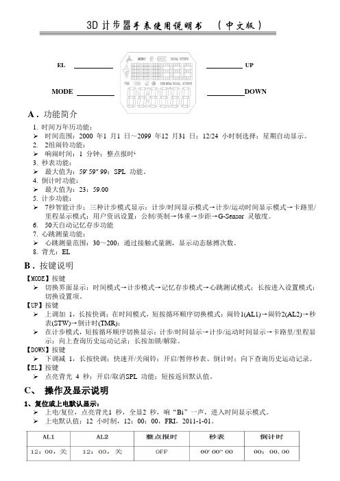
3D计步器手表使用说明书(中文版)EL UPMODE DOWNA . 功能简介1. 时间万年历功能:时间范围:2000 年1 月1 日~2099 年12 月31 日;12/24 小时制选择;星期自动显示。
2. 2组闹铃功能:响闹时间:1 分钟;整点报时i3. 秒表功能:最大值为:59' 59" 99;SPL 功能。
4. 倒计时功能:最大值为:23:59.005. 计步功能:7秒智能计步;三种计步模式显示:计步/时间显示模式→计步/运动时间显示模式→卡路里/里程显示模式;用户资讯设置:公制/英制→体重→步距→G-Sensor 灵敏度。
6. 50天自动记忆存步功能7. 心跳测量功能:心跳测量范围:30~200;通过接触式量测,显示动态脉搏次数。
8. 背光:ELB . 按键说明【MODE】按键切换界面显示:时间模式→计步模式→记忆存步模式→心跳测试模式;长按进入设置模式;切换设置项。
【UP】按键上调加1,长按快调;在时间模式,短按循环顺序切换模式:闹铃1(AL1)→闹铃2(AL2)→秒表(STW)→倒计时(TMR);在计步模式,短按循环顺序切换显示:计步/时间显示→计步/运动时间显示→卡路里/里程显示;向上查询历史运动记录;长按加锁/解除。
【DOWN】按键下调减1,长按快调;快速开/关闹铃;开启/暂停秒表、倒计时;向下查询历史运动记录。
【EL】按键点亮背光4 秒;开启/取消SPL 功能;短按返回默认值。
C、操作及显示说明1、复位或上电默认显示:上电/复位,点亮背光1 秒,全显2 秒,响“Bi”一声,进入时间显示模式。
上电默认值:12 小时制,12:00:00,FRI,2011-1-01。
时间模式显示界面短按【UP】键可循环顺序切换模式:闹铃1(AL1)→闹铃2(AL2)→秒表(STW)→倒计时(TMR),如图所示:按【UP】或【DOWN】键向上/下调整设置项的值,长按【UP】或【DOWN】键2 秒有快调功能。
手表使用说明
手表使用说明1、手表使用说明调校方法:时间的调整校对时间时,如果您要求时间相当精确,先让秒针走到12时位臵拉出表冠至位臵3,顺时针或逆时针转动表冠调整时针和分钟的位臵,当各指针与标准时间(以电视机或收音机为参考)一致时,将表冠推回原位(位臵1)。
日历的调整将表冠拉至位臵2,顺时针方向转动表冠调整日历。
星期日历手表的调整将表冠拉出至位臵2,逆时针转动表冠调整星期,顺时针转动调整日历。
注意事项:手表的日历、星期、月相之调整切勿在手表时间21:00PM~3:00AM之间操作,此期间日历功能正在进行运作,同时也是齿轮齿合度较低的时候,频繁的动作会损伤手表的内部零件。
星期日历跳格,由于制格不同分为快慢两种,第一种在±5分钟之内日历跳格完成,第二种在3小时内日历跳格完成。
如遇采用螺旋式表冠的手表,切勿硬拔,请先逆时针方向旋转打开锁紧的表冠,在调整好时间后,将表冠顺时针方向转动并推入锁紧,以免进水。
如遇带日历的手表需调节日期,请先将日历调到您所需要日期的前一天,之后转动时针来调节日期,当时针经过午夜12点时日期会变更,这样可以避免直接调节日期造成日夜的混淆。
如遇功能复杂的手表,请先详读专门附带的说明书。
2、防水性能的介绍手表的防水性能主要依靠表镜、后盖、表冠等处的防水胶圈,并采用螺旋式表冠,从而达到相应的防水标准。
手表的防水性能通常按其等级分为:不防水(表后盖勿标识)。
防汗(SWEAT-RESISTANT)。
一般性防水(WATER-RESISTANT),30米防水(30M、3ATM、3BAR),50米防水(50M、5ATM、5BAR)。
潜水表100米防水,200米防水,300米防水等。
关于手表的防水性能,国家标准和国际标准都有明确的规定:凡是标明防水的手表,最低要耐受2个大气压,即20米水深处不进水。
30米防水表示手表可以耐受3个大气压,依此类推。
此标准的前提是在进行测试的时候是在实验室条件下:温度保持在20-25摄氏度,且手表和水都呈静止状态。
Timex 数字手表说明书

户外表通用说明书(中文版)
NW:西北 NE:东北 SW:西南 SE:东南 为省电,罗盘会在持续指示方向两分钟后自动停止,此时外圈
表盘的点阵形成一圈。如需再次测量,按A键。
如图:上箭头指向东南(135度
) 此点指东(90度
)
间隔的三点指南(180度 )
连续的三点指北(0度)
可将外圈的三个紧密点和三个 间隔点想象成一个指南针,紧 密三点为针头,间隔三点为针 尾,分别永远指向北和南,如图:
切换显示模式 按D键激活屏幕并切换不同的显示模式
按D键 按D键
钟表模式
按D键 按D键
按D键 按D键
按D键 按D键
秒表模式
罗盘模式
高度计模式
时间设置 在C/F选项之后,“24H”的图标会闪烁。按C键选择12或24小
4
时时制。 按A键确定,之后小时图标闪烁。 按C键调整小时并按A键确定。 小时确定后,分钟图标闪烁。 按C键调整分钟并按A键确定。 重复以上过程来设定年、月、日。
进入磁偏角输入界面,此时显示“dEC”。此时,屏幕左上角 的“E”或“W”开始闪烁,按C键选择磁偏角表示方式,在E( 东)和W(西)之间切换,按A键确定。 此时右上角的角度开始闪烁,按C调整为当地的磁偏角,按A确 定。
14
此时右下角的“on(开)”或“off(关)”闪烁,按C键调成 on启用磁偏角,按A键确定。
圈2
开始 按A
重设 长按A
按C 按C 圈3
停止
按A
11
查看每圈记录:C键—A键—A键……C键—A键
秒表模式
最快一圈
平均配速
第一圈
重设
回到秒表模 式
最后一圈
电子罗盘 按D键进入罗盘模式。 将表面保持水平,将表盘上 符号指向要测量的方向。 罗盘会以三种方式指示方向:以字母缩写表示的方向、角度和
百圣牛GPS腕表PSE-402繁体操作说明书--我没找到简体的将就看吧
防水功能
TREKMATE 具有防水效果。其防水通過 5 ATM 的測試。這代表您可使用 TREKMATE 從事游泳或其它水上運動活動 , 但不應使用在深潛或自由潛水 。 重要! 游泳或與水接觸時勿按壓任何按鈕。當產品浸在水中時,蓄意或無意 間按壓按鈕可能導致故障。
3
應用軟件(Track Star)
T1 與 T2 的時間設定 .............................................................. 18
如何設定 T1 時區 ..................................................................................... 20 如何設定年月日及時分............................................................................ 20
7
產品說明
TREKMATE 特點和功能簡介
● 指針數位(GAL) 全球首創指針數位時間與衛星時間同步精確, 並結合運動手錶的休閒元 素與高科技設計, 既實用又大方。 ● 純數位(GL) 數位時間顯示與衛星時間同步精確,採用高電量電池 GPS 使用時間高達 7 小時. 讓全天候的運動紀錄與定位更加完整, 同樣結合運動手錶的休閒元 素與高科技設計, 既實用又大方。 ● 衛星定位(GPS) 手錶內建小體積高感度 GPS 定位晶片,能同時進行接收及解碼衛星信號, 並記錄及顯示位置坐標,並具有嚮導等功能。 ● 雙重時間(Dual time) TREKMATE 可以同時查看兩個時區的時間 T1 和 T2,您可根據需要設置時間 的時區,另具有定時自動校準時間功能。 ● 運動模式(Sport mode) 運動模式是一項功能強大的戶外運動輔助產品 , 它提供您自行設定及查看運 動過程中的時間、速度、最高速度、距離、高度、所在位置坐標及方向等資 訊,並且可以自動保存最多約 10~20 個小時的運動軌跡資料,通過連接電 腦,將歷史記錄資料上傳至 Track Star 軟體進行管理和永久保存。
PRECIDRIVE GMT 两地时石英腕表 用户手册说明书
PRECIDRIVE GMT 两地时石英腕表用户手册显示和功能GMT 显示 (第 2 时区 - 24 小时)时针 (本地时间)分针秒针日期显示窗口3 档位表冠:I 空档位置 (拧紧*,未拉出)II 日期设置位置 (拧松*,半拉出) III 时间的设置位置 (拧松*,完全拉出)➊➋➌➍➎➏恭喜恭喜您选择了世界知名的瑞士腕表品牌之一雪铁纳®的计时码表。
此表设计严谨,采用高品质材料和部件精心打造而成,一定程度上可以防震、抵御温度变化、防水和防灰尘,这一切都得益于DS (双保险) 技术。
该用户手册适用于搭载 PRECIDRIVE F06.421 GMT 机芯的雪铁纳®石英计时码表。
有关 PRECIDRIVE 腕表的设置和操作,请参考以下说明。
为了保证您的腕表能长期运转正常和走时准确,我们建议您务必注意本手册给出的建议。
DS (双保险) 技术的特点是:– 对刮擦和碰撞具有较强的抗震能力,– 高级耐磨损蓝宝石玻璃镜面,– 表冠内的垫圈和上弦柄周围的垫圈保证了表冠在拉出时,腕表依然可以防水,– 加固的表壳底盖。
设置带螺旋表冠的表款:为了确保更好地防水,一些表款配有螺旋表冠 (6)。
在设置时间或日期之前,您必须首先将表冠 (6) 拧松至位置IB,然后将其拉出至位置II或III。
重要事项:在每个操作完成后,您必须将表冠旋回以确保腕表防水。
建议您不要在水下操作表冠 (6)。
设置 GMT 显示时间 (第 2 时区)• 将表冠 (6) 拉出至位置III;秒针 (3) 会停止。
• 向前或向后旋转表冠 (6),以同时设置 GMT 显示 (第 2 时区) (1) 和分针 (4)。
在这一阶段,无需设置时针 (本地时间) (2) 或日期指针(5)。
• 将表冠 (6) 推回位置I。
此时秒针 (3) 将再次开始运行。
• GMT 显示 (1) 和分针 (4) 设置完毕。
快速调校日期和设置本地时间• 将表冠 (6) 拉出至位置Il。
LBI-39032 钟表 VU 表格 344A4758P1 维护手册说明书
LBI-39032MAINTENANCE MANUALCLOCK/VU METER344A4758P1SPECIFICATIONS*Input V oltage13.8 VDC, nominal9.0 VDC, minimum18.0 VDC, maximumCurrent DrainHigh Intensity (typical)130 mALow Intensity (typical)25 mAMaximum200 mATemperature Range0° to +60°CDisplay ColorClock Green LEDVU 3 Green/4 Yellow/3 Red LEDDisplay TypeClock Four digit 7 segment LEDDisplays hours and minutes, 12/24 hour selectableFlashing seconds colonPM indicator for 12 hour operationLoss of calibration indicator for battery failureVU Meter Ten bar LED bar graphLower right decimal point of clock indicates calibration required Battery Back-Up Power 3.0 VDC, 165 mAh lithium battery to maintain clock operation for up to10 years (typically) without external power--no display* These specifications are typical and are intended for use during servicing.DESCRIPTIONThe electronic digital clock/VU meter option is designed to operate with the desk top station to provide a real time of day clock function and an audio transmit VU meter func-tion. The option consists of a completely assembled board featuring a four digit display, ten element bar graph display and associated circuitry. The option board connects to the desk top station system board via a single four-wire cable.The unit is powered by 13.8 VDC through P203-1 and ground through P203-2. The DC voltage is passed through power diode D1 and regulated by voltage regulator U9 and filter capacitor C4 to 5 VDC. U9 supplies voltage to the 8-bit RISC microcontroller U3, high impedance, non-invert-ing inputs of op-amps U1A and U1B. as a stable voltage reference and through diode D4 to the timekeeping module U2. The input voltage is passed through divider network R13 and R14 to U3-7 (RA1) to provide a loss of power in-dicator to U3.CIRCUIT ANALYSISDigital Electronic ClockThe timekeeping function is performed by U2 and a 32.768 kHz crystal XTL1. The clock output of U2 is con-nected to U3 which provides the driver output for the 7-seg-ment displays U4-U7 through data lines D0-D7 and bipolar transistors Q3-Q6. Data line D4 and D7 are also connected to normally open momentary pushbutton switches SW1 and SW2. These switches are used for setting the time in the dis-plays and also for calibration of the VU meter bar graph dis-play.In addition to the timekeeping function, U2 provides non-volatile RAM when connected to the 3.0 VDC battery through diode D5. The timekeeping function can be sus-tained for up to ten years when the specified battery is in-stalled. When the option board is normally powered through P203-1, diode D5 is reversed biased and there is no current drain. The RAM is used to store calibration information for the VU portion of the option board, in addition to storing the seven segment display and bar graph intensity levels.The clock display is provided by the four 7-segment dis-plays U4-U7 and is active upon power up. A flashing sec-onds colon along with a PM indicator (upper left corner of U4) for the 12 hour clock function is displayed.Battery failure or loss of calibration data is indicated by an indicator in the lower right corner of U7.VU MeterThe VU meter consists of a full wave rectifier/DC-gain block (U1A, U1B, R1-R5, R12, C2, C8-C9 and D2-D3). C2 controls the attack time of the VU meter while the decay time is software controlled. Capacitor C1 is used to DC cou-ple the microphone input. U3 performs a single slope inte-grating A/D conversion using R12, R6, C3 and U3 (RA0). The converter self calibrates by using U3 (RA2) to force a +5 V input to the converter as a reference. The bar graph display/driver circuitry consists of Q1, Q2, U8 and U3. The VU meter provides an audio transmit metering function that permits the user to monitor the microphone output level during transmission.The VU meter is operational only when the microphone is keyed, causing the PTT line (P203-4) to be active (low). This low level is detected through U3 (RA3) and activates the 10-segment bar graph display. The full wave recti-fier/DC-gain block rectifies the microphone input (P203-3) with respect to +5 volts and provides a fixed DC gain of 10. U3 then converts the DC output of this stage via RC net-work (R6 & C3) to a digital representation, which is used by U3 to drive the appropriate bar graph segments. U3 pro-vides a VU decay time of about 400 mS.The VU meter display provides an indication that varies according to the input level on P203-3. As the signal applied gets stronger, more segments on the bar graph illuminate. When the red segments glow, this indicates that audio dis-tortion is being approached and the input level should be ad-justed accordingly.ADJUSTMENTSThe following procedures should be performed to set the digital electronic clock time and mode and to calibrate the VU meter 10-segment display. Normally open, momentary pushbutton switches SW1 and SW2 are used for setting the time and for the calibration of the VU meter.Digital Electronic Clock1.To set the clock mode for either 12 or 24 hour format,press SW1 for 0.5 seconds. The display will show the current mode ("12xx" or "24xx"). Press SW2 to toggle between modes.Copyright© November 1993, Ericsson GE Mobile Communications Inc. LBI-390322.Press SW1 again for 0.5 seconds to set the hour. Thehours will be displayed in high intensity and the minutes in low intensity. Press SW2 to increment the hour by one. Pressing SW2 continually will increment the hour 3 times a second until SW2 is released.3.Press SW1 again for 0.5 seconds to set the minutes. Theminutes will be displayed in high intensity and hour in low intensity. Press SW2 to increment the minutes by one. Pressing SW2 continually will increment the min-ute 3 times a second until SW2 is released.4.Press SW1 again for 0.5 seconds to set the intensity ofthe display. There are four intensity settings: low, me-dium low, medium and high. Press SW2 to increment the current intensity setting, going from low to high and wrapping back around to low.5.Press SW1 again for 0.5 seconds to activate the time-keeping. The time will begin at 0 second of the time which was set in the preceding steps.VU MeterThe VU meter 10-segment display must be properly calibrated before use or whenever the loss of calibration in-dicator is displayed in the lower right corner of the clock display.1.Remove power from the option board.2.Press SW1 while restoring power to the option board.3.Clock display will display a three digit integer rangingfrom 065 to 207.4.Connect a 1 kHz, 107 mV signal to microphone input(P203-3).5.Press SW1 and SW2 to move the integer value up anddown until the first red bar graph segment is lit, then in-crease the integer value until that red segment goes out.6.Press either SW1 or SW2 continuously for 5 seconds tosave the calibration data and return to normal operating mode.HANDLINGSince this option board is powered by a backup battery, care must be taken to prevent shorting of the circuitry when handling or shipping. Do not place in anti-static bags with-out insulating the circuitry.BATTERY REPLACEMENT Should the lithium battery require replacement, discon-nect the option board to remove the 13.8 VDC input and carefully unsolder the battery tabs from the solder side of the board. Install replacement battery as specified in Parts List in same location, observing the polarity of the battery tabs. Dispose of defective battery as required by state or lo-cal regulations.Printed in U.S.A.LBI-39032OUTLINE DIAGRAMCLOCK/VU Meter344A4758P1COMPONENT SIDESOLDER SIDELBI-39032LBI-39032 SCHEMATIC DIAGRAMCLOCK/VU METER344A4758P1(A 0234-00 100, Rev. 0)PARTS LISTCLOCK/VU METER344A4758P1*COMPONENTS ADDED, DELETED OR CHANGED BY PRODUCTION CHANGESLBI-39032。
Memosens 2.0技术应用的数字电子表说明书
Digital with Memosens 2.0 technologyApplication•Long-term monitoring and limit control in processes with stable process conditions •Chemical industry: strong acids/bases, plastic, pulp and paper industry •Power plants (e. g. flue gas cleaning), oil and gas •Incinerator plants•Water and wastewater treatment •Boiler feedwater and cooling water •Well water and drinking water•All industrial and municipal treatment plantsWith ATEX, IECEx, CSA C/US, NEPSI, Japan and INMETRO approvals for use in hazardous areas Zone 0, Zone 1 and Zone 2.Your benefits •Low-maintenance and robust thanks to large PTFE ring junction •Can be used at pressures up to 17 bar (246.5 psi) (absolute)•Process glass for standard applications (application A)•Process glass also for highly alkaline applications (application B)•Process glass for applications in media containing hydrofluoric acid (application F)•Integrated NTC 30K temperature sensor for effective temperature compensation •Optional: for media with low conductivity (reference system AS with salt storage)•Optional: Poison-resistant reference with improved ion trap (reference system TA)Other advantages provided by Memosens technology•Maximum process safety thanks to non-contact, inductive signal transmission •Data security thanks to digital data transmission•Very easy to use as sensor data are saved in the sensor•Predictive maintenance can be performed with the Memobase Plus CYZ71D by recording sensor load data in the sensorProducts Solutions ServicesTechnical Information Memosens CPS11EpH sensor for standard applications in process technology and environmental engineeringTI01493C/07/EN/01.20714869772020-06-29Memosens CPS11E2Endress+HauserFunction and system designMeasuring principlepH measurementThe pH value is used as a unit of measurement for the acidity or alkalinity of a medium. Themembrane glass of the electrode delivers an electrochemical potential that depends on the pH value of the medium. This potential is generated by the selective accumulation of H + ions on the outer layer of the membrane. As a result, an electrochemical boundary layer with an electrical potential difference forms at this point. An integrated Ag/AgCl reference system serves as the required reference electrode.The measured voltage is converted to the corresponding pH value using the Nernst equation.Measuring systemA complete measuring system consists of the following components at least:•pH sensor CPS11E•Transmitter, e. g. Liquiline CM42, CM44x •Memosens data cable CYK10 or CYK20•Assembly•Immersion assembly, e. g. Dipfit CPA111•Flow assembly, e. g. Flowfit CPA250•Retractable assembly, e. g. Cleanfit CPA871•Permanent installation assembly, e. g. Unifit CPA842Additional options are available depending on the application:Automatic cleaning and calibration system, e. g. Liquiline Control CDC903412A00257571Example of a measuring system for pH measurement 1Retractable assembly Cleanfit CPA8712pH sensor CPS11E3Memosens data cable CYK104Liquiline M CM42 two-wire transmitter for hazardous areasMemosens CPS11EEndress+Hauser 3Communication and data processingCommunication with the transmitterAlways connect digital sensors with Memosens technology to a transmitter with Memosens technology. Data transmission to a transmitter for analog sensors is not possible.Digital sensors can store measuring system data in the sensor. These include the following:•Manufacturer data •Serial number •Order code•Date of manufacture •Calibration data •Calibration date•Slope at 25 °C (77 °F)•Zero point at 25 °C (77 °F)•Offset of integrated temperature sensor •Number of calibrations •Calibration history•Serial number of the transmitter used to perform the last calibration or adjustment •Operating data•Temperature application range •pH application range•Date of initial commissioning •Maximum temperature value•Hours of operation under extreme conditions •Number of sterilizations •CIP counter •Sensor loadThe data listed above can be displayed with Liquiline CM42, CM44x, and Memobase Plus CYZ71D.Dependability ReliabilityEasy handlingSensors with Memosens technology have integrated electronics that store calibration data and other information (e. g. total hours of operation or operating hours under extreme measuring conditions).Once the sensor has been connected, the sensor data are transferred automatically to the transmitter and used to calculate the current measured value. As the calibration data are stored in the sensor,the sensor can be calibrated and adjusted independently of the measuring point. The result:•Easy calibration in the measuring lab under optimum external conditions increases the quality of the calibration.•Pre-calibrated sensors can be replaced quickly and easily, resulting in a dramatic increase in the availability of the measuring point.•Thanks to the availability of the sensor data, maintenance intervals can be accurately defined and predictive maintenance is possible.•The sensor history can be documented on external data carriers and in evaluation programs, e. g.Memobase Plus CYZ71D.•The saved application data of the sensor can be used to determine the continued use of the sensor in a targeted manner.Interference immunityData security thanks to digital data transmissionMemosens technology digitizes the measured values in the sensor and transmits the data to the transmitter via a non-contact connection that is free from potential interference. The result:•If the sensor fails or there is an interruption in the connection between the sensor and transmitter,this is reliably detected and reported.•The availability of the measuring point is reliably detected and reported.Memosens CPS11E4Endress+HauserSafetyMaximum process safetyWith inductive transmission of the measured value using a non-contact connection, Memosens guarantees maximum process safety and offers the following benefits:•All problems caused by moisture are eliminated:•No corrosion at the connection•Measured values cannot be distorted by moisture•The transmitter is galvanically decoupled from the medium. Issues concerning "symmetrical high-impedance" or "asymmetry" or the type of impedance converter are a thing of the past.•Electromagnetic compatibility (EMC) is guaranteed by screening measures for the digital transmission of measured values.•Intrinsically safe electronics mean operation in hazardous areas is not a problem. Complete flexibility thanks to individual Ex approvals for all components, such as sensors, cables and transmitters.InputMeasured variablepH value TemperatureMeasuring rangeApplication A •pH: 1 to 12•Temperature: –15 to 80 °C (5 to 176 °F)Application B •pH: 0 to 14•Temperature: 0 to 135 °C (32 to 275 °F)Application F •pH: 0 to 10•Temperature: 0 to 70 °C (30 to 158 °F)Pay attention to the operating conditions in the process.Power supplyElectrical connection2Measuring cable CYK10 or CYK20‣Memosens measuring cable, e. g. Connect the CYK10 or CYK20 to the sensor.For further information on cable CYK10, see BA00118C.Performance characteristicsReference systemAg/AgCl reference lead, bridge electrolyte: gel KCl, 3M, AgCl-free (reference system TA)Memosens CPS11EEndress+Hauser 5InstallationOrientation•Do not install the sensors upside-down.•The installation angle from the horizontal must be at least 15°.An installation angle < 15° is not permitted, as otherwise an air bubble will form. Contact between the membrane glass and the reference lead will then no longer be guaranteed.3Installation angle at least 15° from the horizontal APermitted orientation BIncorrect orientationInstallation instructions•Before screwing in the sensor, make sure the assembly thread, the O-rings and the sealing surface are clean and undamaged and that the thread runs smoothly.•Pay attention to the installation instructions provided in the Operating Instructions of the assembly used.‣Screw in the sensor and tighten by hand with a torque of 3 Nm (2.21 lbf ft) (specifications onlyapply if installing in Endress+Hauser assemblies).For detailed information on removing the moistening cap, see BA01988CEnvironmentAmbient temperature rangeNOTICERisk of damage from frost!‣Do not use the sensor at temperatures below –15 °C (5 °F) .Storage temperature 0 to 50 °C (32 to 122 °F)Degree of protection IP 68 (10 m (33 ft) water column, 25 °C (77 °F), 45 days, 1 M KCl)Electromagnetic compatibility (EMC)Interference emission and interference immunity as per EN 61326-1: 2013ProcessProcess temperature rangeApplication A:–15 to 80 °C (5 to 176 °F)Application B:0 to 135 °C (32 to 275 °F)Application F:0 to 70 °C (32 to 158 °F)Process pressure rangeApplications A and B:0.8 to 17 bar (11.6 to 246.5 psi) absolute Application F:0.8 to 7 bar (11.6 to 101.5 psi) absoluteMemosens CPS11E6Endress+HauserL CAUTIONPressurization of sensor due to prolonged use under increased process pressure Possibility of sudden rupture and injury from glass splinters!‣Avoid fast heating of these pressurized sensors if they are used under reduced process pressureor under atmospheric pressure.‣When handling these sensors, always wear protective goggles and appropriate protective gloves.ConductivityReference system AA, TA:minimum 50 μS/cm (minimized flow; pressure and temperature must be stable)Reference system AS:minimum 0.1 μS/cm (stainless steel flow assembly with grounding;stable and minimized flow; pressure and temperature must be stable)Pressure-temperature ratings4Pressure-temperature ratings A Application AxAtmospheric pressure5Pressure-temperature ratings B Application B F Application FxAtmospheric pressureMemosens CPS11EEndress+Hauser 7Mechanical construction6CPS11E with salt storage. Engineering unit:mm (in)1Memosens plug-in head with process connection 2O-ring with thrust collar3Reference lead4pH reference lead5Salt storage6Junction7Temperature sensor8pH glass membrane7CPS11E with ion trap. Engineering unit: mm (in)1Memosens plug-in head with process connection 2O-ring with thrust collar 3Reference lead 4pH reference lead 5Ion trap 6Junction7Temperature sensor 8pH glass membraneWeightInstalled length 120 mm (4.72 in)225 mm (8.86 in)360 mm (14.17 in)425 mm (16.73 in)Weight40 g (1.4 oz)60 g (2.1 oz)90 g (3.2 oz)100 g (3.5 oz)MaterialsSensor shaftGlass to suit process pH membrane glass Type A, B, F Metal lead Ag/AgClAperture Ring-shaped PTFE diaphragm, sterilizable O-ringFKMProcess coupling PPS fibre-glass reinforced Nameplate ceramic metal oxideTemperature sensor NTC 30KPlug-in headMemosens plug-in head for digital, non-contact data transmission, pressure resistance 16 bar (232 psi)(relative)Process connectionsPg 13.5Memosens CPS11E8Endress+HauserCertificates and approvalsmarkThe product meets the requirements of the harmonized European standards. As such, it complies with the legal specifications of the EU directives. The manufacturer confirms successful testing of the product by affixing to it the mark.Ex approvalATEXII 1G Ex ia IIC T3/T4/T6 Ga IECExEx ia IIC T3/T4/T6 Ga NEPSIEx ia IIC T3/T4/T6 GaCSA C/US•IS Cl. I Div 1, GP A-D Ex ia IIC T3/T4/T6•IS Cl. I Zone 0, AEx ia IIC T3/T4/T6Japan ExEx ia IIC T3/T4/T6 Ga INMETROEx ia IIC T3/T4/T6 GaEx versions of digital sensors with Memosens technology are identified by an orange-red ringon the plug-in head.Pay attention to the instructions for Memosens data cable CYK10 and transmitter CM82.TÜV certificate forMemosens plug-in head Pressure resistance 16 bar (232 psi) relative, minimum three times the safety pressureEACThe product has been certified according to guidelines TP TC 004/2011 and TP TC 020/2011 which apply in the European Economic Area (EEA). The EAC conformity mark is affixed to the product.Ordering informationProduct page /cps11eProduct ConfiguratorOn the product page there is a Configure button to the right of the product image.1.Click this button.The Configurator opens in a separate window.2.Select all the options to configure the device in line with your requirements. In this way, you receive a valid and complete order code for the device.3.Export the order code as a PDF or Excel file. To do so, click the appropriate button on the rightabove the selection window.For many products you also have the option of downloading CAD or 2D drawings of the selected product version. Click the CAD tab for this and select the desired file type using picklists.Scope of deliveryThe delivery comprises:•Sensor in the version ordered •Operating Instructions•Safety instructions for the hazardous area (for sensors with Ex approval)Memosens CPS11EEndress+Hauser 9AccessoriesThe following are the most important accessories available at the time this documentation was issued.‣For accessories not listed here, please contact your Service or Sales Center.Device-specific accessoriesAssembliesUnifit CPA842•Installation assembly for food, biotechnology and pharmaceutics •With EHEDG and 3A certificate•Product Configurator on the product page:/cpa842Technical Information TI01367CCleanfit CPA875•Retractable process assembly for sterile and hygienic applications•For in-line measurement with standard sensors with 12 mm diameter, e.g. for pH, ORP, oxygen •Product Configurator on the product page:/cpa875Technical Information TI01168CDipfit CPA140•pH/ORP immersion assembly with flange connection for very demanding processes •Product Configurator on the product page:/cpa140Technical Information TI00178CCleanfit CPA871•Flexible process retractable assembly for water, wastewater and the chemical industry •For applications with standard sensors with 12 mm diameter•Product Configurator on the product page:/cpa871Technical Information TI01191CCleanfit CPA473•Stainless steel process retractable assembly with ball valve shutoff for particularly reliable separation of the medium from the environment•Product Configurator on the product page:/cpa473Technical Information TI00344CCleanfit CPA474•Plastic process retractable assembly with ball valve shutoff for particularly reliable separation of the medium from the environment•Product Configurator on the product page:/cpa474Technical Information TI00345CDipfit CPA111•Immersion and installation assembly made of plastic for open and closed vessels •Product Configurator on the product page:/cpa111Technical Information TI00112CFlowfit CPA240•pH/ORP flow assembly for processes with stringent requirements •Product Configurator on the product page:/cpa240Technical Information TI00179CFlowfit CPA250•Flow assembly for pH/ORP measurement•Product Configurator on the product page:/cpa250Technical Information TI00041CMemosens CPS11E10Endress+HauserEcofit CPA640•Set comprising adapter for 120 mm pH/ORP sensors and sensor cable with TOP68 coupling •Product Configurator on the product page:/cpa640Technical Information TI00246C Buffer solutionsHigh-quality buffer solutions from Endress+Hauser - CPY20The secondary buffer solutions have been referenced to primary reference material of the PTB (German Federal Physico-technical Institute) or to standard reference material of NIST (National Institute of Standards and Technology) according to DIN 19266 by a laboratory accredited by the DAkkS (German accreditation body) according to DIN 17025.Product Configurator on the product page: /cpy20Measuring cableMemosens data cable CYK10•For digital sensors with Memosens technology•Product Configurator on the product page:/cyk10Technical Information TI00118CMemosens laboratory cable CYK20•For digital sensors with Memosens technology•Product Configurator on the product page: /cyk20。