用Gambit给弯管画结构化网格-教程
Gambit网格划分1
1.基本几何结构的创建和网格化本章介绍了GAMBIT中一个简单几何体的创建和网格的生成。
在本章中将学习到:z启动GAMBITz使用Operation工具箱z创建一个方体和一个椭圆柱体z整合两个几何体z模型显示的操作z网格化几何体z检查网格的品质z保存任务和退出GAMBIT1.1 前提在学习本章之前,认为用户还没有GAMBIT的使用经验,不过,已经学习过前一章“本指南的使用”,并且熟悉GAMBIT界面以及本指南中所使用的规约。
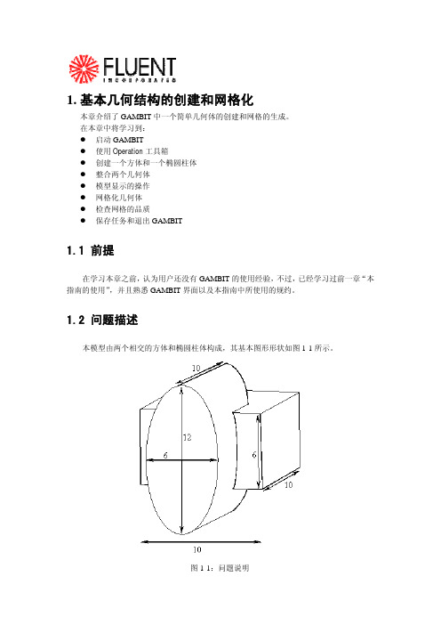
1.2 问题描述本模型由两个相交的方体和椭圆柱体构成,其基本图形形状如图1-1所示。
图1-1:问题说明1.3策略本章介绍使用GAMBIT生成网格的基本操作,特别地,将介绍:z如何使用“top-down”固体建模方法来方便地创建几何体z如何自动生成六面体网格“top-down”方法的意思是用户可以通过生成几何体(如方体、柱体等)来创建几何结构,然后,对它们进行布尔操作(如整合、剪除等),以这种方式,用户不用首先去创建作为基础的点、边和面,就可以快速创建出复杂的几何形体。
一旦创建出一个有效的几何模型,网格就可以直接并且自动地(很多情况下)生成。
在本例子中,将采用Cooper网格化算法来自动生成非结构化的六面体网格。
更复杂的几何结构在生成网格之前可能还需要进行手工分解,这将在后面进行介绍。
本章的学习步骤如下:z创建两个几何体(一个方体和一个椭圆柱体)z整合两个几何体z自动生成网格z检查网格的品质为了使本章的介绍尽量简短,一些必要的步骤被省略了:z调节几何体单边上节点的分布z设置连续介质类型(例如,标识哪些网格区是流体,哪些网格区是固体)和边界类型这些方面的详细内容,也包括其他方面,在随后的章节将涉及到。
1.4步骤输入gambit -id basgeom启动GAMBIT。
这就打开了GAMBIT的图形用户界面(GUI)(图1-2)。
GAMBIT把设定的名称(本例子中为basgeom)作为她将创建的所有文件的词头,如:basgeom.jou。
Gambit网格划分

1.基本几何结构的创建和网格化本章介绍了GAMBIT中一个简单几何体的创建和网格的生成。
在本章中将学习到:z启动GAMBITz使用Operation工具箱z创建一个方体和一个椭圆柱体z整合两个几何体z模型显示的操作z网格化几何体z检查网格的品质z保存任务和退出GAMBIT1.1 前提在学习本章之前,认为用户还没有GAMBIT的使用经验,不过,已经学习过前一章“本指南的使用”,并且熟悉GAMBIT界面以及本指南中所使用的规约。
1.2 问题描述本模型由两个相交的方体和椭圆柱体构成,其基本图形形状如图1-1所示。
图1-1:问题说明1.3策略本章介绍使用GAMBIT生成网格的基本操作,特别地,将介绍:z如何使用“top-down”固体建模方法来方便地创建几何体z如何自动生成六面体网格“top-down”方法的意思是用户可以通过生成几何体(如方体、柱体等)来创建几何结构,然后,对它们进行布尔操作(如整合、剪除等),以这种方式,用户不用首先去创建作为基础的点、边和面,就可以快速创建出复杂的几何形体。
一旦创建出一个有效的几何模型,网格就可以直接并且自动地(很多情况下)生成。
在本例子中,将采用Cooper网格化算法来自动生成非结构化的六面体网格。
更复杂的几何结构在生成网格之前可能还需要进行手工分解,这将在后面进行介绍。
本章的学习步骤如下:z创建两个几何体(一个方体和一个椭圆柱体)z整合两个几何体z自动生成网格z检查网格的品质为了使本章的介绍尽量简短,一些必要的步骤被省略了:z调节几何体单边上节点的分布z设置连续介质类型(例如,标识哪些网格区是流体,哪些网格区是固体)和边界类型这些方面的详细内容,也包括其他方面,在随后的章节将涉及到。
1.4步骤输入gambit -id basgeom启动GAMBIT。
这就打开了GAMBIT的图形用户界面(GUI)(图1-2)。
GAMBIT把设定的名称(本例子中为basgeom)作为她将创建的所有文件的词头,如:basgeom.jou。
GAMBIT网格划分 教程详细版

MESH
-每 EDGE
立釐s键 E量钮釐s
-每 MESH EDGES
a) 而键附ft-首釐ft-那首附那题 E温
必 度拉
必 度拉
边) 而键附ft-首釐ft-那首附那题 EB框
那)
温pp首y
量) 置at附o 釐)
度密必拉
跟)
联长隐ft
定
过)
App首y 定
度-把定
如
定
4板 定 度定 必定 您定 4定
度-把板
定
定 定
定 定
把定
G首o过跟首 点ont鼠o首
板GA立演的能 定
4定
联状种状点能 素网状联状能 点类算现的G节网A能的类算 度-描定
定
度-描板
描定
定
跟)
检
过)
定
操定 G首o过跟首 点ont鼠o首
类网的状算能 立类熟状种
定
如 点鼠鉴跟t 网鉴跟首 演鼠隐速题
定
量) 点鼠鉴跟t 网鉴跟首 演鼠隐速题
如GA立演的能
鉴) 点鉴nt鉴鼠鉴量 定
f)
点鉴nt鉴鼠鉴量
g) App首y定
菜隐量t长 菜隐量t长
定
度-您板
度0如熟鉴pt长 定
描如略鉴隐g长t
vo首u骤鉴定度 定
度-您板
(
)
必板
定
跟)
点网状A能 范类种节立状
过) 点网状A能状 网状A种 点藐种的算熟状网
e)
Apply
Copy Translate
0 12 0
f)
FIT TO WINDOW
g)
h) Global
i)
Apply
Gambit基础教程

第二章前处理软件-Gambit网格划分基础第一节网格生成技术网格生成是CFD计算的一个关键步骤,当物体外形复杂程度较大时,网格生成技术将起到至关重要的作用。
网格可分为两大类:结构网格和非结构网格。
一、结构网格生成技术过去普遍采用的是结构网格。
所谓结构网格就是网格拓扑相当于矩形域内均匀网格的网格。
为了便于处理物面边界条件,常要求结构网格具有贴体性质,即通过坐标变换,使物体的几何边界成为坐标面(线)。
现有的结构网格的生成方法基本上可分为以下四大类:1、代数生成方法。
其特点是根据边界上规定的网格点位置(或者附加一些参考点位置),用插值方法确定所有其它网格点的位置。
它具有简便灵活、计算速度快的突出优点,但对复杂的几何形状往往难以找到合适的插值函数。
2、保角变换方法。
它能生成完全正交的贴体网格,计算机时也少,但局限于二维情况,且对物体形状往往有很大限制。
3、偏微分方程方法。
其特点是通过求解偏微分方程的边值问题来确定区域内网格点分布。
它具有较大的适应性,且生成的网格质量很好,特别是椭圆型方程生成的网格通常是光滑和均匀变化的,同时调和函数的极值性质保证了网格生成时物理空间和计算空间之间的一一对应关系,但网格较密时,一般需要较长的计算时间。
4、变分原理方法。
在这类方法中,将生成网格所希望满足的要求表示成某个目标函数(泛函)取极值。
这种方法常用于生成自适应网格,因为可以比较方便地将自适应网格的要求用某个变分原理来表示,然后再导出和该变分原理相应的偏微分方程,即Euler 方程。
采用结构网格总的优点是可以方便准确地处理边界条件,计算精度高,并且可以采用许多高效隐式算法和多重网格法,计算效率也较高。
缺点是对复杂外形的网格生成较难,甚至难以实现;即使生成多块结构网格,块与块之间的界面处理又十分复杂,因而在使用上受到限制。
二、非结构网格生成技术为了灵活方便地数值模拟绕复杂外形的流动,在20世纪80年代末人们提出了采用非结构网格的技术手段,现已成为研究的热点之一。
gambit做网格的简单介绍
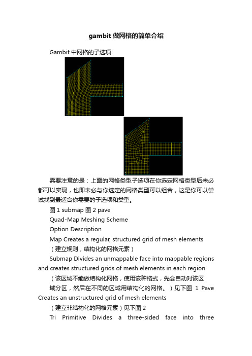
gambit做网格的简单介绍Gambit中网格的子选项需要注意的是:上面的网格类型子选项在你选定网格类型后未必都可以实现,也即未必与你选定的网格类型可以组合,这是你可以尝试找到最适合你需要的子选项和类型。
图1 submap 图2 paveQuad-Map Meshing SchemeOption DescriptionMap Creates a regular, structured grid of mesh elements(建立规则,结构化的网格元素)Submap Divides an unmappable face into mappable regions and creates structured grids of mesh elements in each region (该区域不能做结构化网格,使用该种格式,先会自动对该区域分区,然后在不同的区域用结构化的网格。
)见下图1 Pave Creates an unstructured grid of mesh elements(建立非结构化的网格元素)见下图2Tri Primitive Divides a three-sided face into threequadrilateralregions and creates a mapped mesh in each region(主要针对三边的情况,若为多条边,则无法使用次方法)Wedge Primitive Creates triangular elements at the tip of a wedge-shaped face and creates a radial mesh outward from the tip(四边形网格不存在该选项,只有与tri混合时才会有该选项)如上图所示,一般情况下,对一个四边形区域进行quad-map划分,但是,并不是所有的四边形都符合这类划分,想要quad-map划分,必须满足下面两点:节点类型(上面的图中,就是四个角点的类型)对应边(eadg)的插值点的数目是否相等,只有相等才可以划分成quad格式Quad-map应用的节点类型的详细介绍:一般情况下,只有多边形组成一个逻辑矩形时,才可以划分为quad-map网格。
gambit二维喷射管网格划分
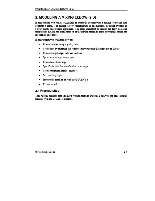
MODELING A MIXING ELBOW (2-D)2. MODELING A MIXING ELBOW (2-D)In this tutorial, you will use GAMBIT to create the geometry for a mixing elbow and then generate a mesh. The mixing elbow configuration is encountered in piping systems in power plants and process industries. It is often important to predict the flow field and temperature field in the neighborhood of the mixing region in order to properly design the location of inlet pipes.In this tutorial you will learn how to:•Create vertices using a grid system•Create arcs by selecting the center of curvature and the endpoints of the arc•Create straight edges between vertices•Split an arc using a vertex point•Create faces from edges•Specify the distribution of nodes on an edge•Create structured meshes on faces•Set boundary types•Prepare the mesh to be read into FLUENT 4•Export a mesh2.1 PrerequisitesThis tutorial assumes that you have worked through Tutorial 1 and you are consequently familiar with the GAMBIT interface.© Fluent Inc., Mar-06 2-1Problem Description MODELING A MIXING ELBOW (2-D)2.2 Problem DescriptionThe problem to be considered is shown schematically in Figure 2-1. A cold fluid enters through the large pipe and a warmer fluid enters through the small pipe. The two fluids mix in the elbow.Figure 2-1: Problem specification2-2 © Fluent Inc., Mar-06MODELING A MIXING ELBOW (2-D) Strategy2.3 StrategyIn this tutorial, you will build a 2-D mesh using a “bottom-up” approach (in contrast to the “top-down” approach used in Tutorial 1). The “bottom-up” approach means that you will first create some vertices, connect the vertices to create edges, and connect the edges to make faces (in 3-D, you would stitch the faces together to create volumes). While this process by its very nature requires more steps, the result is, just as in Tutorial 1, a valid geometry that can be used to generate the mesh.The mesh created in this tutorial is intended for use in FLUENT 4, so it must be a single block, structured mesh. However, this mesh can also be used in any of the other Fluent solvers. This type of mesh is sometimes called a mapped mesh, because each grid point has a unique I, J, K index. In order to meet this criterion, certain additional steps must be performed in GAMBIT and are illustrated in this tutorial. After creating the straight edges and arcs that comprise the geometry, you will create two faces: one for the main flow passage (the elbow) and one for the smaller inlet duct. The mesh is generated for the larger face using the Map scheme; this requires that the number of grid nodes be equal on opposite edges of the face. You will force GAMBIT to use the Map scheme to mesh the smaller face as well.Several other features are also demonstrated in this tutorial:•Using a background grid and “snap-to-grid” to quickly create a set of vertices.•Using “pick lists” as an alternative to mouse clicks for picking entities.•Specifying a non-uniform distribution of nodes on an edge.•Setting boundary types.•Exporting a mesh for a particular Fluent solver (FLUENT 4 in this case).© Fluent Inc., Mar-06 2-3Procedure MODELING A MIXING ELBOW (2-D)2.4 ProcedureStart GAMBIT.Step 1: Select a Solver1.Choose the solver you will use to run your CFD calculation by selecting the followingfrom the main menu bar:Solver →FLUENT 4This selects the FLUENT 4 solver as the one to be used for the CFD calculation.The choice of a solver dictates the options available in various forms (for example, the boundary types available in the Specify Boundary Types form). The solver currently selected is indicated at the top of the GAMBIT GUI.2-4 © Fluent Inc., Mar-06MODELING A MIXING ELBOW (2-D) Procedure © Fluent Inc., Mar-06 2-5 Step 2: Create the Initial Vertices1. Create vertices to define the outline of the large pipe of the mixing elbow.TOOLS →COORDINATE SYSTEM →DISPLAY GRIDThis command sequence opens the Display Gridform.a) Check to ensure that Visibility is selected.This ensures that the background grid will be visible when it is created.b) Select X (the default) to the right of Axis .c) Enter a Minimum value of –32, a Maximum value of 32, and an Increment of 16. d) Click the Update list button.Procedure MODELING A MIXING ELBOW (2-D) This creates a background grid with four cells in the x direction and enters thex coordinates in the XY_plane X Values list.e)Select Y to the right of Axis.f)Enter a Minimum value of –32, a Maximum value of 32, and an Increment of 16.g)Click the Update list button.This creates a background grid with four cells in the y direction and enters they coordinates in the XY_plane Y Values list.h)Check that Snap is selected under Options.The vertices you create later in this step will be “snapped” to points on thegrid where the grid lines intersect.i)Select Lines (the default) to the right of Grid.The grid will be displayed using lines rather than points.j)Click Apply.GAMBIT creates a four-by-four grid in the graphics window. To see thewhole grid, you must zoom out the display (see Figure 2-2). You can zoom outthe display by pressing and holding down the right mouse button while movingthe cursor vertically upward in the graphics window.2-6 © Fluent Inc., Mar-06MODELING A MIXING ELBOW (2-D) Procedure© Fluent Inc., Mar-062-7Figure 2-2: Four-by-four grid to be used for creating vertices NOTE: You cannot use the FIT TO WINDOWcommand button (located on the Global Control toolpad) to zoom out the display because GAMBIT does not treat the grid as a model component to be fit within the graphics window.k) Ctrl -right-click the nine grid points shown in Figure 2-3.“Ctrl -right-click” indicates that you should hold down the Ctrl key on the keyboard and click on the point at which the vertex is to be created using the right mouse button.You can use the UNDOcommand buttonif you create any of the verticesincorrectly.Procedure MODELING A MIXING ELBOW (2-D)2-8 © Fluent Inc., Mar-06 A DC BF GE H IFigure 2-3: Create vertices at grid pointsl) Unselect the Visibility check box in the Display Grid form and click Apply .The grid will be removed from the graphics window and you will be able to clearly see the nine vertices created, as shown in Figure 2-4.MODELING A MIXING ELBOW (2-D) Procedure© Fluent Inc., Mar-062-9Figure 2-4: Vertices for the main pipeProcedure MODELING A MIXING ELBOW (2-D) 2-10 © Fluent Inc., Mar-06 Step 3: Create Arcs for the Bend of the Mixing Elbow1. Create an arc by selecting the following command buttons in order:GEOMETRY →EDGE →CREATE EDGERThis command sequence opens the Create Circular Arcform.a) Retain the default Method .Notice that the Center list box is yellow in the Create Circular Arc form at this point. The yellow color indicates that this is the active field in the form, and any vertex selected will be entered into this box on the form.b) Shift -left-click the vertex in the center of the graphics window (vertex E in Figure2-5).The selected vertex will appear red in the graphics window and its name will appear in the Center list box under Vertices in the form.D B F GEFigure 2-5: Vertices used to create arcsc)Left-click in the list box to the right of End-Points to accept the selection of vertexE and make the End-Points list box active.!Alternatively, you could continue to hold down the Shift key and click the right mouse button in the graphics window to accept the selection of thevertex and move the focus to the End-Points list box.Note that the End-Points list box is now yellow—that is, this is now the activelist box, and any vertex selected will be entered in this box.d)Shift-left-click the vertex to the right of the center vertex in the graphics window(vertex F in Figure 2-5).The vertex will turn red.e)Select the vertex directly below the one in the center of the graphics window(vertex D in Figure 2-5).f)Click Apply to accept the selected vertices and create the arc.© Fluent Inc., Mar-06 2-112-12 © Fluent Inc., Mar-062. Repeat the above steps to create a second arc. The center of the arc is the vertex in thecenter of the graphics window (vertex E in Figure 2-5). The endpoints of the arc are the vertices to the right and below the center vertex that have not yet been selected(vertices G and B, respectively, in Figure 2-5). The arcs are shown in Figure 2-6.Figure 2-6: Vertices and arcsStep 4: Create Straight Edges 1.Create straight edges for the large pipe.GEOMETRY →EDGE →CREATE EDGERThis command sequence opens the Create Straight Edgeform.a)Shift -left-click the left endpoint of the smaller arc (vertex D in Figure 2-7).A DCB F G H IFigure 2-7: Vertices used to create straight edgesb)Shift-left-click the vertices marked C, A, and B in Figure 2-7, in order.© Fluent Inc., Mar-06 2-132-14 © Fluent Inc., Mar-06c) Click Apply to accept the selection of the vertices.Three straight edges are drawn between the vertices.d) Shift -left-click the vertices marked F, H, I, and G in Figure 2-7, in order.e) Click Apply to accept the selection of the vertices.The graphics window with the arcs and straight edges is shown in Figure 2-8.Figure 2-8: Arcs and edgesStep 5: Create the Small Pipe for the Mixing ElbowIn this step, you will create vertices on the outer radius of the bend of the mixing elbow and split the large arc into three smaller arcs. Next, you will create vertices for the inlet of the small pipe. Finally, you will create the straight edges for the small pipe.1.Create vertices on the outer radius of the bend, and split the large arc into threesections.GEOMETRY →EDGE →SPLIT/MERGE EDGESThis command sequence opens the Split Edgeform.a)Select the large arc as the edge to split by using the Edge pick list.Note that you could select the edge in the graphics window; a pick listprovides an alternate way of picking an element.i.Left-click the black arrow to the right of the Edge list box in the Split Edgeform.© Fluent Inc., Mar-06 2-15This action opens the Edge List form. There are two types of pick-listforms: Single and Multiple. In a Single pick-list form, only one entity canbe selected at a time. In a Multiple pick-list form, you can select multipleentities.ii.Select edge.2 under Available in the Edge List form.!Note that the Available names may be different in your geometry,depending on the order in which you created the edges.iii.Click the −−−> button to pick edge.2.edge.2 will be moved from the Available list to the Picked list. The large arcis the edge that should be selected and shown in red in the graphicswindow.iv.Close the Edge List form.This method of selecting an entity can be used as an alternative to Shift-left-click in the graphics window. See the GAMBIT User’s Guide formore information on pick lists.2-16 © Fluent Inc., Mar-06b)Select Real connected (the default) under Type in the Split Edge form.You should select this option because the edge you selected is real geometry,not virtual geometry, and because you want the two edges created by the splitto share the vertex created when GAMBIT does the split. See the GAMBITModeling Guide for more information on real and virtual geometry.c)Select Point (the default) to the right of Split With.You will split the edge by creating a point on the edge and then using thispoint to split the edge.d)Select Cylindrical from the Type option menu.You can now use cylindrical coordinates to specify where GAMBIT shouldsplit the edge.e)Input a value of –39.93 degrees next to t under Local.This is the angle between the horizontal direction and the position of the right-hand side of the opening of the small pipe on the bend of the mixing elbow, asshown in Figure 2-1.f)Click Apply.The large arc is split into two smaller arcs and a vertex is created.g)Use the Edge List form (or Shift-left-click in the graphics window) to select thelarger of the two arcs just created (edge.9).h)Input a value of –50.07 degrees next to t under Local.This is the angle between the horizontal direction and the position of the left-hand side of the opening of the small pipe on the bend of the mixing elbow (-90° + 39.93°), as shown in Figure 2-1.i)Click Apply.The arc is split into two parts and a second vertex is created on the bend ofthe mixing elbow, as shown in Figure 2-9.© Fluent Inc., Mar-06 2-172-18© Fluent Inc., Mar-06Figure 2-9: Vertices created on outer radius of mixing elbow bend2. Create points at the small inlet.GEOMETRY →VERTEX →MOVE/COPY VERTICESThis command sequence opens the Move / Copy Vertices form.© Fluent Inc., Mar-062-19a) Select the second vertex created on the bend of the mixing elbow.b) Select Copy under Vertices in the Move / Copy Vertices form.c) Select Translate (the default) under Operation .d) Enter the translation vector (0, -12, 0) under Global to create the new vertex at aposition 12 units below the vertex you selected.The inlet is 12 units below the second point created on the outer radius of the bend.Note that GAMBIT automatically fills in the values under Local as you enter values under Global .e) Click Apply .2-20 © Fluent Inc., Mar-06 f) Click the FIT TO WINDOWcommand button at the top left of the GlobalControl toolpad to scale the model to fit into the graphics window.g) Select the vertex just created in the graphics window.h) Enter the translation vector (4, 0, 0) under Global in the Move / Copy Vertices formto create the new vertex at a position 4 units to the right of the vertex you selected. i) Click Apply .The vertices are shown in Figure 2-10.Figure 2-10: Vertices to define the small pipe3. Create straight edges for the small pipe.GEOMETRY →EDGE →CREATE EDGEThis command sequence opens the Create Straight Edge form.© Fluent Inc., Mar-062-21a) Create straight edges for the small pipe by selecting the vertices marked K, L, M, and J in Figure 2-11, in order, and accepting the selection. K JMLFigure 2-11: Vertices to be used to create small pipeThe small pipe is shown (with the large pipe) in Figure 2-12.2-22© Fluent Inc., Mar-06Figure 2-12: Completed small pipeStep 6: Create Faces From Edges 1.Create a face for the large pipe.GEOMETRY →FACE →FORM FACEThis command sequence opens the Create Face From Wireframeform.a)Shift-left-click each edge of the large pipe, in turn, to form a continuous loop.!The large pipe is created from the 10 edges shown in Figure 2-13. If you select an incorrect edge, click Reset in the Create Face From Wireframe formto unselect all edges, and then reselect the correct edges.© Fluent Inc., Mar-06 2-232-24© Fluent Inc., Mar-06Figure 2-13: Edges used to create face for large pipeNote that the edges must form a continuous loop, but they can be selected in any order. An alternative method to select several edges is to Shift -left-drag a box around the edges. The box does not have to completely enclose the edges; it only needs to enclose a portion of an edge to select it. The edges will be selected when you release the mouse button.b) Click Apply to accept the selected edges and create a face.The edges of the face will turn blue.2. Create a face for the small pipe by selecting the four edges shown in Figure 2-14 andthen accepting the selected edges.© Fluent Inc., Mar-062-25Figure 2-14: Edges used to create face for small pipeStep 7: Specify the Node DistributionThe next step is to define the grid density on the edges of the geometry. You will accomplish this graphically by selecting an edge, assigning the number of nodes, and specifying the distribution of nodes along the edge.1.Specify the node density on the inlet and outlet of the large pipe.MESH →EDGE →MESH EDGESThis command sequence opens the Mesh Edgesform.a)Shift-left-click the edge marked EA in Figure 2-15.2-26 © Fluent Inc., Mar-06© Fluent Inc., Mar-06 2-27 EAED ECEG EH EIEJ EBEFEEFigure 2-15: Edges to be meshedThe edge will change color and an arrow and several circles will appear on the edge.b) Shift -left-click the edge marked EB in Figure 2-15.c) Check that Apply is selected to the right of Grading in the Mesh Edges form andthat Successive Ratio is selected in the Type option menu.The Successive Ratio option sets the ratio of distances between consecutive points on the edge equal to the specified Ratio .d) Enter 1.25 in the text entry box to the right of Ratio .Alternatively, you can slide the Ratio slider box (the small, gray rectangle with a vertical line in its center that is located on the slider bar) until 1.25 is displayed in the Ratio text box.2-28 © Fluent Inc., Mar-06e) Select the Double sided check box under Grading .If you specify a Double sided grading on an edge, the element intervals are graded in two directions from a starting point on the edge. GAMBIT determines the starting point such that the intervals on either side of the point are approximately the same length.Note that Ratio changes to Ratio 1 and Ratio 2 when you select the Double sided check box. In addition, the value you entered for Ratio is automatically entered into both the Ratio 1 and the Ratio 2 text entry boxes.f) Select Interval count from the option menu under Spacing and enter a value of 10 inthe text entry box. Check that Apply is selected to the right of Spacing .GAMBIT will create 10 intervals on the edge.g) Click the Apply button at the bottom of the form. Figure 2-16 shows the mesh on the inlet and outlet edges of the large pipe. EAED ECEG EH EIEJ EFEE EBFigure 2-16: Edge meshing on inlet and outlet of large pipe© Fluent Inc., Mar-06 2-29 2. Mesh the four straight edges of the large pipe.a) Select the edges marked EC, ED, EE, and EF in Figure 2-16.b) Check that Apply is selected to the right of Grading in the Mesh Edges form andclick the Default button to the right of Grading .GAMBIT will unselect the Double sided check box and set the Ratio to 1.c) Check that Apply is selected to the right of Spacing and select Interval count fromthe option menu.d) Enter a value of 15 in the text entry box below Spacing and click the Apply buttonat the bottom of the form. Figure 2-17 shows the mesh on the straight edges of the large pipe. EAED ECEG EH EIEJ EFEE EBFigure 2-17: Mesh on the straight edges of the large pipe3.Mesh the edge connecting the two pipes.a)Select the edge marked EG in Figure 2-17.b)Check that Apply is selected to the right of Grading in the Mesh Edges form andenter a value of 1 for the Ratio.c)Check that Apply is selected to the right of Spacing, select Interval count from theoption menu, and enter a value of 6 in the text entry box below Spacing.d)Click the Apply button at the bottom of the form.4.Mesh the two edges on the outer radius of the bend of the mixing elbow.a)Select the edge marked EH in Figure 2-17. The arrow should point towards thesmall pipe. Shift-middle-click the edge to reverse the direction of the arrow if necessary.!The arrow is small and you may have to zoom into the edge to see it. It is located near the center of the edge.b)Select the edge marked EI in Figure 2-17. The arrow should point towards thesmall pipe. Shift-middle-click the edge to reverse the direction of the arrow if necessary.c)Check that Apply is selected to the right of Grading in the Mesh Edges form andenter a value of 0.9 for the Ratio.d)Check that Apply is selected to the right of Spacing, select Interval count from theoption menu, and enter a value of 12 in the text entry box below Spacing.e)Click the Apply button at the bottom of the form.The mesh on the two edges on the outer radius of the bend is shown in Figure2-18.2-30 © Fluent Inc., Mar-06© Fluent Inc., Mar-06 2-31 EAED ECEG EH EIEJ EFEE EBFigure 2-18: Mesh on outer bend of pipe5. Set the grading for the inner bend of the mixing elbow.a) Select the edge marked EJ in Figure 2-18.b) Check that Apply is selected to the right of Grading in the Mesh Edges form andenter a value of 0.85 for the Ratio .c) Select the Double sided check box.d) Unselect the Apply check box to the right of Spacing .You will not set a spacing on this edge, instead you will let GAMBIT calculate the spacing for you when it meshes the face. You will mesh the face using a mapped mesh, so the number of nodes on the inner bend of the mixing elbow must equal the number of nodes on the outer bend, and GAMBIT will determine the correct number of nodes for you automatically.2-32© Fluent Inc., Mar-06e) Unselect the Mesh check box under Options and click the Apply button at thebottom of the form.You unselected the Mesh check box because at this point you do not want to mesh the edge; you only want to apply the Grading to the edge. GAMBIT will mesh the edge using the specified Grading when it meshes the large pipe of the mixing elbow in the next step.Figure 2-19 shows the edge meshing for the mixing elbow geometry.© Fluent Inc., Mar-062-33Figure 2-19: Edge meshing for the mixing elbowStep 8: Create Structured Meshes on Faces 1.Create a structured mesh for the large pipe.MESH →FACE →MESH FACESThis command sequence opens the Mesh Facesform.a)Shift-left-click the large pipe in the graphics window.Note that four of the vertices on this face are marked with an “E” in thegraphics window; they are End vertices. Therefore, GAMBIT will select theMap Type of Scheme in the Mesh Faces form. See the GAMBIT ModelingGuide for more information on Map meshing.b)Click the Apply button at the bottom of the form.GAMBIT will ignore the Interval size of 1 under Spacing, because the mappedmeshing scheme is being used and the existing edge meshing fully determinesthe mesh on all edges.2-34 © Fluent Inc., Mar-06© Fluent Inc., Mar-06 2-35 Notice that GAMBIT calculates the number of nodes on the inner bend of the mixing elbow and displays these nodes before creating the mesh on the face.The face will be meshed as shown in Figure 2-20.Figure 2-20: Structured mesh on the large pipe of the mixing elbow2. Mesh the small pipe of the mixing elbow.a) Select the small pipe in the graphics window.You will force GAMBIT to use the Map scheme to mesh the smaller face.b) In the Mesh Faces form, select Quad from the Elements option menu underScheme and Map from the option menu to the right of Type .This is an example of “enforced mapping”, where GAMBIT automatically modifies the face vertex type on the face to satisfy the chosen meshing scheme. See the GAMBIT Modeling Guide for more information on face vertex types.c) Retain the default Interval size of 1 under Spacing and click the Apply button at thebottom of the form.The structured mesh for the entire elbow is shown in Figure 2-21.2-36© Fluent Inc., Mar-06Figure 2-21: Structured mesh for the mixing elbowStep 9: Set Boundary Types1.Remove the mesh from the display before you set the boundary types.This makes it easier to see the edges and faces of the geometry. The mesh is not deleted, just removed from the graphics window.a)Click the SPECIFY DISPLAY ATTRIBUTEScommand button at the bottom of the Global Control toolpad.b)Select the Off radio button to the right of Mesh near the bottom of the form.c)Click Apply and close the form.2.Set boundary types for the mixing elbow.ZONES →SPECIFY BOUNDARY TYPESThis command sequence opens the Specify Boundary Types form.© Fluent Inc., Mar-06 2-372-38© Fluent Inc., Mar-06Note that FLUENT 4 is shown as the chosen solver at the top of the form. The Specify Boundary Types form displays different Type s depending on the solver selected.a) Define two inflow boundaries.i. Enter the name inflow1 in the Name text entry box.If you do not specify a name, GAMBIT will give the boundary a defaultname based on what you select in the Type and Entity lists.ii. Select INFLOW in the Type option menu.iii.Change the Entity to Edges by selecting Edges in the option menu below Entity.iv.Shift-left-click the main inflow for the mixing elbow in the graphics window (marked EA in Figure 2-22) and click Apply to accept the selection.EBEAEKFigure 2-22: Boundary types for edges of mixing elbowThis edge will be set as an inflow boundary.v.Enter inflow2 in the Name text entry box.vi.Check that INFLOW is still selected in the Type option menu and select the edge marked EK in Figure 2-22 (the inlet for the small pipe). Click Apply to acceptthe selection of the edge.b)Define an outflow boundary.i.Enter outflow in the Name text entry box.ii.Change the Type to OUTFLOW by selecting OUTFLOW in the option menu below Type.iii.Select the main outflow for the mixing elbow (the edge marked EB in Figure 2-22) and click Apply to accept the selection.© Fluent Inc., Mar-06 2-392-40 © Fluent Inc., Mar-06 The inflow and outflow boundaries for the mixing elbow are shown in Figure 2-23. (NOTE: To display the boundary types in the graphics window, select the Show labels options on the Specify Boundary Typesform.)Figure 2-23: Inflow and outflow boundaries for the mixing elbowNote that you could also specify the remaining outer edges of the mixing elbow as wall boundaries. This is not necessary, however, because when GAMBIT saves a mesh, any edges (in 2-D) on which you have not specified a boundary type will be written out as wall boundaries by default. In addition, when GAMBIT writes a mesh, any faces (in 2-D) on which you have not specified a continuum type will be written as FLUID by default. This means that you do not need to specify a continuum type in the Specify Continuum Types form for this tutorial.MODELING A MIXING ELBOW (2-D) Procedure © Fluent Inc., Mar-06 2-41 Step 10: Export the Mesh and Save the Session1. Export a mesh file for the mixing elbow.File → Export → Mesh…This command sequence opens the Export Mesh File form. Note that the File Type is Structured FLUENT 4 Grid.a) Enter the File Name for the file to be exported (2delbow.GRD ).b) Click Accept .The file will be written to your working directory.2. Save the GAMBIT session and exit GAMBIT.File → ExitGAMBIT will ask you whether you wish to save the current session before youexit.Click Yes to save the current session and exit GAMBIT.Summary MODELING A MIXING ELBOW (2-D)2.5 SummaryThis tutorial shows you how to generate a 2-D mesh using the “bottom-up” approach. Since the mesh is to be used in FLUENT 4, it was generated in a single block, structured fashion. Several other features that are commonly used for 2-D mesh generation were also demonstrated, including entering vertices using a background grid, creating straight edges and arcs, and specifying node distributions on individual edges. As compared to Tutorial 1, which omitted some details, all steps required to create a mesh ready to read into the solver were covered, including how to set boundary types, choose a specific Fluent solver, and finally write out the mesh file.2-42 © Fluent Inc., Mar-06。
Gambit教育训练-2D弯管

FLUENT TEAM
Confidential
5
產生方格平面
• Operation
↓ TOOLS COMMAND BUTTON
↓ Tools
↓
COORDINATE SYSTEM
↓ coordinate system
↓
DISPLAY GRID
FLUENT TEAM
↓ zones
↓
SPECIFY BOUNDARY TYPE
FLUENT TEAM
Confidential
31
設定邊界區域
Name:V1 Type:VELOCITY_INLET Entity:選擇Edges
Shift + 滑鼠左鍵 點選邊界為入口的邊
V2及出口邊界相同步驟處理
FLUENT TEAM
Confidential
建立Face
FLUENT TEAM
Confidential
25
Boolean Operations
• Operation
↓ GEOMETRY COMMAND BUTTON
↓ Geometry
↓
FACE COMMAND BUTTON
↓ face
↓ Boolean Operation
↓ Unite Faces
FLUENT TEAM
Confidential
28
產生網格
選擇Face Elements:Tri(三角錐網格) Spacing:2
FLUENT TEAM
Confidential
29
產生網格
FLUENT TEAM
Confidential
30
gambit网格

3 模型的网格划分当用户点击Operation工具框中的Mesh命令按钮时,GAMBIT将打开Mesh子工具框。
Mesh子工具框包含的命令按钮允许用户对于包括边界层、边、面、体积和组进行网格划分操作。
与每个Mesh 子工具框命令设置相关的图标如下。
图标命令设置Boundary LayerEdgeFaceVolumeGroup3.1 边界层3.1.1 概述边界层确定在与边和/或者面紧邻的区域的网格节点的步长。
它们用于初步控制网格密度从而控制相交区域计算模型中有效信息的数量。
示例作为边界层应用的一个示例,考虑包括一个代表流体流过管内的圆柱的计算模型。
在正常环境下,很可能在紧靠管道壁面的区域内流体速度梯度很大,而靠近管路中心很小。
通过对壁面加入一个边界层,用户可以增大靠近壁面区域的网格密度并减小靠近圆柱中心的网格密度——从而获得表征两个区域的足够的信息而不过分的增大模型中网格节点的总数。
一般参数要确定一个边界层,用户必须设定以下信息:•边界层附着的边或者面•确定边界层方向的面或者体积•第一列网格单元的高度•确定接下来每一列单元高度的扩大因子•确定边界层厚度的总列数用户还可以设定生成过渡边界层——也就是说,边界层的网格节点类型随着每个后续层而变化。
如果用户设定了这样一个边界层,用户必须同时设定以下信息:•边界层过渡类型•过度的列数3.1.2 边界层命令命令详细说明图标Create Boundary Layer建立附着于一条边或者一个面上的边界层Modify Boundary Layer更改一个现有边界层的定义更改边界层标签Modify Boundary LayerLabelSummarize Boundary在图形窗口中显示现有边界层LayersDelete Boundary Layers删除边界层生成边界层Create Boundary Layer命令允许用户在一条边或者一个面附近定义网格节点步长。
要生成一个边界层,用户必须设定以下参数:•定义•过渡特性•附着实体和方向设定边界层定义要定一边界层,用户必须设定两类特征:•尺寸•内部连续性•角形状尺寸特征包括诸如边界层列数以及第一列高度等因数。
- 1、下载文档前请自行甄别文档内容的完整性,平台不提供额外的编辑、内容补充、找答案等附加服务。
- 2、"仅部分预览"的文档,不可在线预览部分如存在完整性等问题,可反馈申请退款(可完整预览的文档不适用该条件!)。
- 3、如文档侵犯您的权益,请联系客服反馈,我们会尽快为您处理(人工客服工作时间:9:00-18:30)。
实例 90度弯管内流体的流动分析
本实例通过对简单三维弯管内流体流动的分析,介绍运用FLUENT进行数值仿真计算的基步骤。
一、实例概述
在实际输水、输油过程中经常会遇到弯管管路。
如图1.1为水平放置的90度水平弯管,空气从左侧进入,从右侧出去,空气的入口流速为0.01m/s。
下面我们就用FLUENT来进行管内流场的模拟。
图1.1 弯管基本尺寸
二、模型的建立
1.双击GAMBIT的桌面快捷方式,弹出GAMBIT启动对话框,单击run按钮,即
启动了GAMBIT。
图1.2 GAMBIT启动对话框
2.单击,在Creat Real Circular Face
面板的Radius对话框中输入10,在Plan面板中选择YZ,单击Apply得到如下图1.4所示的圆面。
图1.3 圆的绘制
图1.4 在YZ平面上的圆
3. 单击右击,在Sweep face 中选择face.1,在Path选项中选择Vector,在单击Define按钮,在Vector Definition面板中选择X轴正方向,在大小中选择100,如图1.6所示,然后单击Apply按钮即得到图1.7所示的圆柱体。
图1.5 Sweep face面板
图1.6 Vector Definition 面板
图1.7 圆柱体
4.弯管的建立,需要移动坐标原点。
如下图 1.8所示,单击
,建立新的坐标原点。
新的坐标系如图1.9所示。
图1.8 坐标面变换对话框
图1.9 新的坐标原点
5.弯管的建立,单击,在Face 中选择face2,转动角度为90度,转动轴为Z轴正方向,单击Apply即可。
图1.10弯管的绘制
图1.11 弯管图
6.采用与上一步建立圆柱体相同的方法建立另支直管,通过拉伸弯管的面来得到另一个直管,从而得到三维的弯管模型,如图1.12所示。
图1.12 弯管物理模型
三、网格的画分
1.激活另一个坐标系。
选择c-sys.1。
图2.1 激活坐标面板
图2.2 选择坐标
2.在入口面上进行网格画分。
2.1单击,输入(0,0,0),单击Apply 即可得到原点。
图2.3 原点的绘制
2.2单击,选择vertex1和vertex5,建立一条直线,如
图2.5所示。
图2.4 线的绘制
图2.5 建立的线
2.3 单击,选择刚才建立的直线,绕x轴复制旋转135度,再旋转-135度,即可得到二条直线,如图2.7所示。
图2.6 复制、旋转操作面板
图2.7 得到的二条直线
2.3 要将这三条直线用点进行分割。
单击,分别选择这三条直线,在Value 对话框中输入0.666。
即可得到如图2.9所示的三个分割点。
图2.8 分割线面板
图2.9 分割的三点
2.4 单击,在Center边框中选择最上方的点,在End-Points边框中选择下面的两个点。
单击Apply,即可得到如图2.11所示的圆弧。
图2.10 圆弧面板
图2.11 圆弧
2.5 单击,将圆弧复制旋转3份以及边2份,得到如图2.13所示的图形。
图2.12 复制、旋转面板
Figure2.13 圆弧图形
2.6单击,在面板中选择四条圆弧生成面域,得到如图2.14所示的图形。
Figure2.14 生成的面域
2.7 单击,即出现Split Face对话框,在上面选择大圆,在下面选择新生成的圆弧面域。
Figure2.15 Split Face对话框
图2.16生成的面域
2.8单击,在edges中选择四条较短的边,在Face中选择圆环,单击Apply。
图2.17 投影面板
2.9单击,选择all,单击Apply;采用同样的方法删除多余的点得到如下图2.19所示的图形。
图2.18 删除边按钮
图2.19 最后分块
2.10 单击,选择圆内的四条相同的线段和圆弧,在interval size 中输入0.5,单击Apply即可。
同时,可以得到如图2.21所示的图形。
图2.20 mesh Edges 面板
图2.21 线网格
2.11 单击,在Faces中选择圆上的5个面,单击Apply,即可得到如下图2.23所示的面网格。
图2.22 Mesh Faces 面板
图2.23 面网格
2.12 体网格的画分,单击,在Volumes 中选择Volume.1(即第一个圆柱体),使用六面体结构化网格,采用Cooper的网格画分方法。
在interval size 中输入1,即可得到如图2.25所示的体网格。
图2.24 Mesh Volumes 面板
图2.25 体网格
2.13 采用相同的方法对其它两个体画网格。
即可得到如下图2.26所示的网格。
图2.26 最终的结构化网格
四、边界条件的设定
3.1 单击,在Type 中选择Velocity Inlet,在Face 中选择入口的5个面,单击Apply即可。
同理,选择出口的一个面,在Type 中选择Pressure Outlet即可。
图2.27 边界条件设定对话框
图2.28 面选择对话框
五、导出mesh文件
单击File Export Mesh,即出现如图2.30所示,如果是二维图形,则需要选上2D复选框。
三维图形则不用选择。
在作图过程中,注意观察Command 对话框,如图2-31所示。
图2.29 导出Mesh面板1
图2.30 导出Mesh面板2
图2.31 Command 对话框
六、导入Fluent计算
将画好的网格文件导入Fluent计算即可。
由于应操作比较简单,大家对照书本操作即可,再这里就不再详述。