EX245-SPR2-X35_EN_060125
常用金属材料机械性能一览表-
伊顿电动机断路保护器
电动机保护断路器PKZ
1.1 xStart系列电动机保护断路器
1
电动机保护断路器PKZ . . . . . . . . . . . . . . . . . . . . . . . . . . . . . . . . . . . . . . . . . . . . . . . . . . . . 3
PKE电子式电动机保护断路器 . . . . . . . . . . . . . . . . . . . . . . . . 8
标准辅助触点 . . . . . . . . . . . . . . . . . . . . . . . . . . . . . . . . . . . . 10
辅助触点、分励脱扣器、欠压脱扣器 . . . . . . . . . . . . . . . . . . 12
P
P
kW kW
440 V
P kW
500 V 660 V 690 V
P
P
kW kW
额定 持续 电流
Iu A
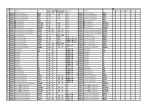
电动机保护断路器,“1”类和“2”类配合
–
–
–
–
0.06 0.16
–
0.06 0.06 0.06 0.12 0.25
0.06 0.09 0.12 0.12 0.18 0.4
0.09 0.12 0.18 0.25 0.25 0.63
2.5…4
56
4…6.3
88
6.3…10 140
8…12
168
10…16
224
16…20
280
20…25
350
25…32
448
10…16
224
16…25
伟肯变频器用户手册
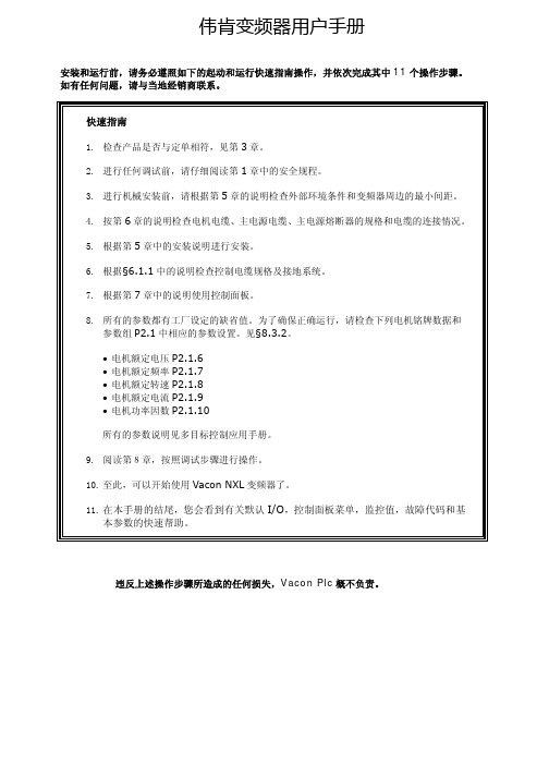
伟肯变频器用户手册安装和运行前,请务必遵照如下的起动和运行快速指南操作,并依次完成其中11个操作步骤。
如有任何问题,请与当地经销商联系。
快速指南1. 检查产品是否与定单相符,见第3章。
2. 进行任何调试前,请仔细阅读第1章中的安全规程。
3. 进行机械安装前,请根据第5章的说明检查外部环境条件和变频器周边的最小间距。
4. 按第6章的说明检查电机电缆、主电源电缆、主电源熔断器的规格和电缆的连接情况。
5. 根据第5章中的安装说明进行安装。
6. 根据§6.1.1中的说明检查控制电缆规格及接地系统。
7. 根据第7章中的说明使用控制面板。
8. 所有的参数都有工厂设定的缺省值。
为了确保正确运行,请检查下列电机铭牌数据和参数组P2.1中相应的参数设置。
见§8.3.2。
• 电机额定电压P2.1.6• 电机额定频率P2.1.7• 电机额定转速P2.1.8• 电机额定电流P2.1.9• 电机功率因数P2.1.10所有的参数说明见多目标控制应用手册。
9. 阅读第8章,按照调试步骤进行操作。
10. 至此,可以开始使用Vacon NXL变频器了。
11. 在本手册的结尾,您会看到有关默认I/O,控制面板菜单,监控值,故障代码和基本参数的快速帮助。
违反上述操作步骤所造成的任何损失,Vacon Plc概不负责。
目录VACON NXL用户手册目录1 安全指导2 EU认证3 收货4 技术数据5 安装6 电缆和接线7 控制面板8 调试9 故障跟踪10 选件卡OPT-AA的描述11 选件卡OPT-AI的描述VACON NXL多目标控制应用手册vacon • 3Vacon China电话: +86-10-51280006 传真: +86-10-65813733 24小时支持热线: +86-137******** Email :***************.cn关于VACON NXL 用户手册和多目标控制应用手册恭喜您选择了Vacon NXL 变频器所提供的平滑控制!用户手册将为您提供有关Vacon NXL 变频器的安装,调试和操作的必要信息。
en55024标准名称
en55024标准名称
EN 55024是欧洲电子设备用电磁兼容性标准的一个重要名称。
它规定了电子设备在电磁环境中的性能要求,以确保设备在遇到电磁干扰时能正常工作,同时不会对其它设备产生干扰。
EN 55024标准适用于各种类型的电子设备,包括计算机、通信设备、家用电器、工业设备等。
根据这一标准,电子设备应具备抵抗电磁场干扰、抵抗电静电放电、抵抗快速瞬变干扰等能力。
根据EN 55024标准的要求,电子设备应该通过各种测试,以验证其在特定的电磁环境中的表现。
这些测试包括:
1. 抗传导干扰测试:验证设备是否能够抵抗来自电源线和信号线的传导干扰;
2. 抗辐射干扰测试:验证设备是否能够抵抗来自电磁场中的辐射干扰;
3. 静电放电测试:验证设备是否能够抵抗来自静电放电的干扰;
4. 快速瞬变测试:验证设备是否能够抵抗来自突然的电压和电流变化引起的干扰。
通过遵循EN 55024标准,设备制造商可以确保其产品在电磁环境中能够正常运行,并且不会对其他设备造成干扰。
这对于确保电子设备的可靠性和互通性至关重要。
总结起来,EN 55024标准为电子设备的电磁兼容性提供了统一的要求和测试方法,以确保设备在电磁环境中的稳定性和可靠性。
制造商和用户都应该密切遵守这一标准,以确保设备在使用过程中不会受到电磁干扰的影响。
负压隔离器说明
dzprc
16 17 18 19 20 21 22 23 24
25 26 27 28 29 30
31
排水球阀 触摸屏 电器柜 变频器 CPU 模块 安装导轨 电源模块 PLC 接线端子 MMC 存储卡 防安全门锁 急停开关 电磁阀 防爆灯具 插座 手动蝶阀 αβ阀
316L 不锈钢,1.5” 套
苏州东中机械设备有限公司
2015-12-21
第 12 页
PQ 确认的目的:在安装确认和运行确认的基础上,根据使用厂家的具体生产工艺加入 相应的试验品进行试验,确认设备的运行性能符合设计要求,并符合新版 GMP 的相关要求 详细文本资料在做现场验证时提供
7.售后服务
第 11 页
dzprc
保修内容:设备质保期为1年,自设备安装调试验收合格之日起计算,质保期内公司提 供免费维修服务。 (1) 在质保期内的保修内容
不锈钢桶
过滤器及其它
压差表 压差变送器 手套 喷枪 喷枪快速接头 氧含量传感器 手套圈 氮气流量计 氮气球阀
过滤效率 99.993
个
过滤效率 H13
套
SMC 气管接头;PU 管
路;pull 仪表、初效 套
过滤器等
0~250Pa/500Pa
个
0‐250PA
个
8Y15 32A
支
枪 1 把;气枪 1 把 把
1) 公司按照双方签订的合同内容提供设备的安装、调试,验证合格后,提供现场操作 及维修、管理人员的培训;培训的具体时间、地点、人数由用户公司协商安排。
2) 质保期内技术人员将会跟踪设备的运行情况,如产品运行不正常,用户就产品问题 向公司技术部门咨询,判定是否属于质量问题。用户可以通过售后电话咨询有关技 术问题,并得到明确的解决方案。若在电话中不能解决的问题,我司将在1小时内 响应用户的服务需求,并在48小时内到现场。
萨福铝焊机说明书

B - 安装调试 ............................................................................................................10 1. 拆除包装 .......................................................................................................10 2. 送丝机连接...................................................................................................10 3. 主电源的电路连接 .....................................................................................10 4. 焊枪的连接...................................................................................................10
中文
目录
安全说明 .....................................................................................................................2
A - 总体介绍 ...............................................................................................................7 1. 装置简介 .........................................................................................................7 2. 焊接设备组成 ................................................................................................7 3. 前面板描述.....................................................................................................8 4. 选配件..............................................................................................................8 5. OPTIPULS i / i W技术规格 .............................................................................8 6. 尺寸和重量.....................................................................................................9 7. 冷却装置的技术规格......................................................................................9
ZS-24系列和ZS-35系列产品说明书

How to OrderOptionOptionPiping direction Part no.Bracket Panel mountPanel mount + Front protection coverRear portedRear portedBottom ported Rear portedBottom ported Rear portedBottom portedZS-24-A ZS-24-D ZS-35-A ZS-35-C ZS-35-B ZS-35-F ZS-35-EFor vacuum/compound pressureFor positive pressure 80ISE 02N 80ZSE 02N –0.1 to 1 MPa –0.1 to 2 MPaRated pressure range8080H 0 to –101 kPa –100 to 100 kPaRated pressure range8080FNPN open collector 1 output PNP open collector 1 output NPN open collector 2 outputs PNP open collector 2 outputsNPN open collector 2 outputs + Analog voltage output/Auto-shift switching PNP open collector 2 outputs + Analog voltage output/Auto-shift switching NPN open collector 2 outputs + Analog current output/Auto-shift switching PNP open collector 2 outputs + Analog current output/Auto-shift switchingInput/OutputN P A B R T S VNote) Fixed unit ISE80H: MPaOthers : MPa, kPaWith unit display switching function Fixed SI unit Note)Initial value psiOption 1NilMPOption 3Note) All texts in both English and JapaneseOperating Note)manual b (Booklet)—b (CD-ROM)Calibration certificate ———Nil Symbol YWb (Booklet)—b (CD-ROM)Calibrationcertificateb b b Symbol K T R PipingR1/4(M5 female threaded)Rear portedBottom portedNPT1/4(M5 female threaded)G1/4(M5 female threaded)Rc1/8URJ1/4TSJ1/402N02F02R1/4(M5 female threaded)NPT1/4(M5 female threaded)Rc1/8URJ1/4TSJ1/402LN02L C01A2B2C01L A2L B2LNoneWith bracketRear portedBottom portedBottom portedOption 2NilABPanel mountWith bracket Note)Rear portedBottom portedPanel mount + Front protection coverRear portedCDNote) Rear ported onlyTable 1Made to OrderNote) Not applicable to the rated pressure range 0 to 2MPa specification. Refer to page 743 for detail.Wetted parts: Stainless steel 316L Lead wire length 3 m Restrictor installed fittingSymbolSpecifications-X500 Note)-X501-X510ZS-24-AZS-35-AZS-24-DZS-35-CZS-35-BZS-35-FZS-35-EM MMade to OrderRefer to Table 1 below.Operating Note)manual ®2-Color Display Digital Pressure Switch For General FluidsSeries ZSE80/ISE80732。
VDE插座标准DIN_VDE_0620-1_2005(中文)

— 安全特低压用插头、固定式插座和移动式插座 本标准不适用于下列电器附件: — 工业用用插头、固定式插座和移动式插座; — 器具耦合器;
注 3:器具耦合器适用 DIN EN 60320(VDE 0625)系列标准。
— 超低压用插头、固定式插座和移动式插座;
注 4:超低压值按 IEC/TR3 61201 出版物测定。
35多位插座两个或以上插座的组合36电器插座嵌入电器中或固定在电器上的插座37可拆线插头或可拆线移动式插座设计成可调换软线的插接装置38不可拆线插头或不可拆线移动式插座设计成经过插接装置制造商的接线和装配后与软线形成一个结构单元的插接装置参见14139模压插接装置通过使预制构部件和软线接头的绝缘材料模压而制成的不可拆线插接装置
2 规范性引用文件
下列文件中的条款通过本标准的引用而成为本标准的条款。凡是注日期的引用文件,其随后所 有的修改单(不包括勘误的内容)或修订版均不适用于本标准,然后,鼓励根据本标准达成协议的 各方研究是否可使用这些文件的最新版本。凡是不注日期的引用文件,其最新版本适用于本标准。
3
DIN VDE0620-1(VDE 0620-1):2005-04
对于配备无螺纹端子的固定式插座,额定电流限于 16A。 本标准不涉及暗装埋入式插座的要求。它只包括插座试验必需的明装插座的要求。
注 1:埋入式插座的一般要求由 DIN EN 60670-1(VDE 0606-1)规定。
本标准还适用于电线组件中的插头和电线加长组部件用插头和移动式插座。本标准还适用于作 为电器一部分的插头和插座, 除非有关电器的标准另有规定;还适用于严酷条件下的插接装置以及 配备 DIN EN 60127(VDE 0820)电器熔断器的插接装置。
- 1、下载文档前请自行甄别文档内容的完整性,平台不提供额外的编辑、内容补充、找答案等附加服务。
- 2、"仅部分预览"的文档,不可在线预览部分如存在完整性等问题,可反馈申请退款(可完整预览的文档不适用该条件!)。
- 3、如文档侵犯您的权益,请联系客服反馈,我们会尽快为您处理(人工客服工作时间:9:00-18:30)。
No. EX##-OMJ1011SI UnitEX245-SPR2-X35Digital Input ModuleEX245-DX1-X36Digital Output ModuleEX245-DY1-X371. Safety (4)2. Product Summary (8)2.1. Feature (8)2.2. Structure (9)3. General Specifications (10)4. Valve Manifold (11)5. Installation (12)5.1. Mounting (12)5.2. Wiring (14)6. Commissioning (16)6.1. Switch setting (16)6.2. Configuration (19)6.3. Parameterisation (21)6.4. Connection to the SIEMENS PLC S7 (23)7. Diagnosis (27)7.1. Setting the diagnostic mode (27)7.2. Standard diagnostic information (29)7.3. Extended diagnostic Information (31)7.4. Diagnostic usage when connected to the SIEMENS PLC S7 (36)8. SI Unit - EX245-SPR2-X35 (39)8.1. Parts and description (39)8.2. Specifications (40)8.3. LED indicators (41)8.4. Block diagram (43)9. Digital Input Module - EX245-DX1-X36 (44)9.1. Parts and description (44)9.2. Specifications (45)9.3. Wiring (46)9.4. Process data (46)9.5. LED indicators (47)9.6. Block diagram (47)10. Digital Output Module - EX245-DY1-X37 (48)10.1. Parts and description (48)10.2. Specifications (49)10.3. Wiring (50)10.4. Process data (50)10.5. LED indicators (51)10.6. Block diagram (51)11. Dimensions (52)11.1.VQC2000 manifold (52)11.2. VQC4000 manifold (53)12. Troubleshooting (54)12.1. EX245-SPR2-X35 (54)12.2. EX245-DX1-X36 (55)12.3. EX245-DY1-X37 (55)This manual contains essential information to prevent possible injury and damage to users and others, and property, and to ensure correct handling.Please confirm understanding the definition of the following messages (signs) before going on to read the text, and always follow the instructions.Also read carefully the instruction manual of relevant equipment or apparatus before use.♦Operator♦ This manual has been written for those who have knowledge of machinery and apparatus that use pneumatic equipment and have full knowledge of assembly, operation and maintenance of such equipment.♦ Please read this manual carefully and understand it before assembling, operating or providing maintenance to the product.♦Usage Restrictions♦ This product is designed for use in general equipment for factory automation. Never use this product with equipment or apparatus that directly concerns human lives*1, or which malfunction or failure can cause a huge loss.*1: Equipment or apparatus that directly matters human life means the following:•Medical equipment such as life support systems or equipment used in operating rooms.•Compulsory equipment required by law such as the Fire Prevention Law, Construction Law and etc.•Equipment or apparatus that conforms with those mentioned above.♦ Contact our sales department when the product is planned to be used for the system*2 including equipment that concerns itself with the safety of persons or that seriously affects the public. This usage needs special consideration*3.*2: The system including equipment that concerns itself with the safety of persons or that seriously affects the public means the following:•Nuclear reactor control systems in nuclear power plants, safety protection systems or othersystems important for safety in nuclear power facilities•Driving control systems of mass transportation systems, and flight control systems•Equipment or apparatus that comes into contact with foods or beverages*3: Special consideration means discussing usage with our engineers to establish a safe system designed as fool-proof, fail-safe, redundant and etc.♦ Special consideration of safety or maintainability should be taken to prevent hazard or loss caused by a failure or malfunction that is likely to occur in certain probability due to environmental stress (deterioration).The special consideration means fully review of the equipment or apparatus in design stage and to establish a backup system in advance such as a redundant system or fail-safe system.NOTE♦ Follow the instructions given below when handling the product:Otherwise a risk of damage or operating failure could result.♦ The instructions on selection (installation, wiring, environment of use, adjustment, operation and maintenance) described below must also be followed.∗Product specifications•Operate the product with the specified voltage.Operation with a voltage beyond specifications could cause malfunction or damage of the product.•Reserve a space for maintenance.Be sure to keep space for maintenance when designing layout of the product.•Do not remove labels.Otherwise maintenance error and misreading of an operation manual could cause damage or malfunction. It may also result in nonconformity to safety standards.♦ Precautions on handling∗Installation•Do not drop, hit or apply excessive shock to the product.•Follow the specified tightening torque on installation.Excessive tightening torque can break screws.∗Wiring•Do not bend the cables, or apply excessive force by placing heavy objects on them.Wiring with bending stress or tensile stress can cause breakage of the cables.•Connect wires and cables correctly.Incorrect wiring can damage the product depending on condition of the wiring.•Do not connect wires while the power is on.Otherwise it can damage the product causing damage or malfunction.•Do not lay wires or cables with power cable or high-voltage cable in the same wiring route.Otherwise the wires to the product can be interfered with noise or induced surge voltage from power lines or high-voltage lines causing malfunction.Lay the wires to the product and each device separate from those for power lines or high- voltage lines.•Verify the insulation of wiring.Poor insulation (interference with other circuit, poor insulation between terminals, etc.) canintroduce excess voltage or current to the product or device causing damage.•Take proper measurements against noise by noise filter etc. when the product is incorporated in equipment or devices.Otherwise interference from noise can cause malfunction.•Low safety voltage (SELV/PELV in accordance with EN 60950) must be used for all power and signal voltages.∗Environment•Select the proper type of protection according to the environment of operation.IP65 protection is achieved when the following conditions are met.(1) By connecting the product properly with the communication line and power cable with M12connectors at both ends, and(2) By installing the product and manifold valves properly.Use suitable cover, etc. when installing in an environment where water always splashes onthe product.NOTE•Take sufficient shielding measures when the product is installed in the following places.Insufficient measures can cause malfunction or failure.Verify the effect of the measures after installation of the product in equipment or devices:(1) A place where noise due to static electricity is generated(2) A place where electric field strength is high(3) A place where there is radioactive irradiation(4) A place near power line(5) A place where water splashes on the product•Do not use the product near by a place where electric surges are generated.Internal circuit elements of the product can deteriorate or break when equipment generating a large surge (electromagnetic lifter, high frequency induction furnace, motor, etc.) is located near the product. Provide surge protection, and avoid interference.•Use the product equipped with surge absorber when a surge-generating load such as a relay or solenoid valve is driven directly.Direct drive of a surge-generating load can damage the product.•Prevent foreign matter such as remnant of wires from entering the product.Take proper measures for the remnant not to enter the product in order to prevent failure ormalfunction.•Do not expose the product to vibration or impact.Otherwise failure or malfunction could be caused.•Keep within the specified ambient temperature range.Otherwise failure or malfunction could be caused.•Do not use the product in a place where temperature suddenly changes even if it stays within the specified range.•Do not expose the product to heat radiation from a heat source located nearby.Otherwise malfunction could be caused.∗Adjustment and Operation•Use precision screwdriver with small flat blade when setting DIP switch and rotary switch.∗Maintenance•Before performing maintenance, make sure to turn off the power supply, stop supplied air, release the residual air in the piping into the atmosphere, and verify that the pneumatic system is open to the air.Otherwise an unexpected operation of a system component can occur.•Perform maintenance and check regularlyOtherwise an unexpected malfunction of the system can occur due to a malfunction of theproduct.•Perform a proper functional check.Stop operation when an abnormality is observed such that the device does not work properly.Otherwise an unexpected malfunction of the system component can occur.•Do not use solvents such as benzene, thinner or other to clean the product.It can damage the surface of the body and erase the indication on the body.Use a soft cloth to remove stains. For heavy stains, use a cloth soaked with diluted neutraldetergent and fully squeezed, then wipe up the stains again with a dry cloth.2.1. FeatureThis SI Unit represents a PROFIBUS DP slave for SMC pneumatic valves. It is also designed for digital and analogue data control by connecting compatible EX245 modules. They can be used within rugged industrial environments, especially within the automotive plants.The SI Unit has following properties:(1) IP65 protection(2) Up to 32 solenoid valves(3) Up to 128 digital inputs(4) Up to 64 digital outputs independent of solenoid valves(5) Up to 8 modules (limited by the total current consumption)(6) Integrated diagnostic and protection function(7) Galvanically isolated power supplies (PROFIBUS DP, US1 for logic / sensors, US2 for valves /loads, US3 and 4 for external loads)(8) Free module configurationCompatible EX245 modules:・EX245-DX1-X36 (16 digital inputs)・EX245-DY1-X37 (8 digital outputs)2.2. StructureNo. ComponentsFunction 1 SI UnitFieldbus and valve interface and supply voltage to modules 2 Digital input moduleSupply voltage to sensors and input digital data 3 Digital output moduleOutput to electric loads 4 End plateEnd plate of module 5 Solenoid valves Operate pneumatic devicesFig. 2-1 System structure 2. Digital input module(EX245-DX1-X36)3. Digital output module(EX245-DY1-X37)4. End plate (EX245-EA2-X50)5. Solenoid valves1. SI Unit(EX245-SPR2-X35)Table. 3-1 EX245 series general specificationsItem SpecificationRated voltage 24 VDC1 msec. or lessAllowable instantaneouselectrical stopProtection class IP65 (when fully installed or fitted with protective cover)(comply with IEC 60529)Applicable standard CE Marking *Withstand voltage 500 VAC 1 min. (between FE and all accessible terminals) Insulation resistance 10 MΩ or more(500 VDC is given between FE and all accessible terminals) Ambient temperature Operation: -5 °C to 50 °CStorage: -20 °C to 60 °CAmbient humidity 35% to 85% RH (non-condensing)Vibration resistance 5 Hz to 9 Hz (constant amplitude) 1.75 mm9 Hz to 150 Hz (constant acceleration) 4.9 m/s22 hours for each direction X, Y and Z(comply with IEC 61131-2)Impact resistance 147 m/s2 is given 3 times for each direction X, Y and Z(comply with IEC 61131-2)Operating environment No corrosive gas*Note: EMC directive (89/336/EEC)EN 61000-6-2/2001, EN 55011/1998+A1+A2EX245 product series can use the following valve manifold:・VQC1000 / 2000 / 4000・SV1000 / 2000 / 3000 / 4000・VSR8-4/8-2, VSS8-4/8-2Refer to catalogue and technical operation manual for details of solenoid valves, manifolds, etc. Contact SMC sales for its compatibility with other solenoid valves.5.1. MountingCautionTo prevent manifold components being damaged, apply the recommended tightening torque.Mount the manifold using the 8 mounting positions on the base with screws.Required screws are as follows:① 2 x M5 (End plate: torque = 1.5 N⋅m)② 2 x M5 (SI Unit: torque = 1.5 N⋅m)③ 4 x M4 or M5 (Valve manifold: refer to valve manifold catalogue)Fig. 5-1 Required screwsAll manifolds are mounted using 8 screws (except VQC4000 which uses 7 screws).5.1.1. Valve manifold connectionConnect the valve manifold with the 2 screws on the SI Unit.Fig. 5-2 Valve manifold connectionCautionFor protection rating of IP65 to be ensured, apply the recommended tightening torque and make sure that the O-ring are positioned correctly on the screw.5.1.2. Module connectionConnect the modules with the 2 modular adaptor assemblies and a joint assembly.① 2 x Modular adaptor assembly (torque = 1.3 N⋅m)② 1 x Joint assemblyFig. 5-3 Module connectionCaution・For protection rating of IP65 to be ensured, modular adaptor assemblies and joint assembly must be installed between each module correctly.・To prevent the modules and assemblies being damaged, apply the recommended tightening torque.5.2. WiringCautionTo prevent damage, all voltages to the SI Unit must be turned off (i.e. de-energized) before the modules are installed or removed.Wire the grounding cable, Bus cables and Power cable.① M5, FE terminal screw (torque = 1.5 N ⋅m) ② M12, Bus connector (IN) ③ M12, Bus connector (OUT) ④7/8”, Power connectorFig. 5-4 Screw and connector allocation5.2.1. Bus / Power connectionThe Bus (OUT) is used for looping through connections. If the bus cable is not looped through, cover the Bus (OUT) with a dummy cap so that a protection rating of IP65 is ensured.Caution・ For reasons of EMC a secure connection to the cable shield must be established on the Bus /(IN / OUT) and Power.・ Power and bus lines must be installed correctly.・ To prevent components of the EX245 from being damaged, the supply lines for the electronicsand for the load voltage must be protected externally with a fuse.③②④IN OUTRemarksN.C. 1 1 N.C. Not usedBus_A 2 2 Bus_APROFIBUS A (galvanically isolated) N.C. 3 3 N.C.Not usedBus_B 4 4 Bus_BPROFIBUS B (galvanically isolated)Shield5 5 ShieldShieldFig. 5-5 Pin allocation of Bus connectorPin Remarks 1 0 V (US2) 2 0 V (US1) 3 FE 4 24 V (US1) 5 24 V (US2)Fig. 5-6 Pin allocation of Power connector5.2.2. FE terminalThe SI Unit must be connected to FE (Functional Earth) to divert electromagnetic interference. Connect to the grounding cable with FE terminal screw on the SI Unit.The other end of the grounding cable should be terminated to ground potential.5.2.3. Sensor / Load connectionRegarding the wiring of each module, refer to following section:・ EX245-DX1-X36: 9.3, page-46 ・ EX245-DY1-X37: 10.3, page-50IN / PinsOUT / Sockets6.1. Switch settingThe switches are located inside the SI Unit, behind the Function switch cover on the front.Using the DIP / rotary switches:・ Unscrew the cover and hinge it upwards.・ The DIP / rotary switches can be adjusted with a small flat-blade screwdriver. The points of thearrows on the rotary switches should be aligned with the required numbers.・ Tighten the cover again, making sure that the seals are positioned correctly. (torque = 0.3 N ⋅m)Fig. 6-1 Accessing the DIP / rotary switches6.1.1. Setting the PROFIBUS addressSet the PROFIBUS address with the switches. Valid addresses are 1 to 125. Set the hundreds with DIP switch, the tens with the left-hand rotary switch and the units with the right-hand rotary switch. Changing address will not take effect until the SI Unit has been powered OFF and then back ON again.Fig. 6-2 Switches for setting the PROFIBUS addressHundreds Tens UnitsSwitch setting Value Switch setting Value Switch setting ValueON 1OFF 00 to 9 0 to 9 0 to 90 to 9Tens Units O N 1 2 3Diagnostic modePROFIBUS addressMaximum number of valvesPROFIBUS networkOFF ON ModeADDRESSx100 x10 x14Termination6.1.2. Setting the maximum number of valvesSelect the maximum number of valves connected with the SI Unit. Changing this setting will not take effect until the SI Unit has been powered OFF and then back ON again.Fig. 6-3 Switch for setting the maximum number of valves6.1.3. Setting the diagnostic modeThe SI Unit supports three diagnostic modes. Changing this setting will not take effect until the SI Unit has been powered OFF and then back ON again.Switch settingNo. 2 No. 3Mode DescriptionOFF OFF Mode 1Extended diagnostic information consists of only simpledevice-related diagnostic data.OFF ON Mode 2Extended diagnostic information consists of detaileddevice-related diagnostic data.ON OFF Mode 3Extended diagnostic information consists of device-related,module-related and channel-related diagnostic data.Fig. 6-4 Switches for setting the diagnostic modeSwitch settingDescriptionON Max. 32 coils. OFF Max. 16 coils.Maximum number of valvesDiagnostic mode6.1.4. Setting the PROFIBUS network terminationThe end nodes on a PROFIBUS network must be terminated to avoid reflections on the bus lines.The SI Unit is equipped with a switch to enable termination. If the SI Unit is the end node on the network, the termination should be set to ON.ON OFF OFFFig. 6-5 Switch for setting the PROFIBUS network termination Switch Setting DescriptionON Termination is enabled.OFF Termination is disabled.6.2. ConfigurationThe EX245-SPR2-X35 is a modular station that consists of several modules. Setup your DPmaster’s software to reflect the configuration of your system.6.2.1. GSD file and symbol filesIn order to configure the EX245-SPR2-X35 with your DP master’s software the appropriate GSD file is required. In addition to slave-typical entries (ID Number, Revision, etc.), the GSD file alsocontains a selection of identifiers.In order to represent the EX245-SPR2-X35 in your DP master’s software the appropriate symbol files is required.Current GSD file and symbol files can be found on the Internet under PROFIBUS International: ・URL: ・GSD file: SMC_1410.gsd・Symbol files: EX245_2N.dib (standard case)EX245_2D.dib (diagnostic case)EX245_2S.dib (special operating mode)6.2.2. Module identifierEach module has its own identifier.Table. 6-1 Overview of identifier for EX245-SPR2-X35DP identifierModule name Occupied bytesSiemens IEC 61158 Valves (32 coils) 4 bytes 32DO 23hValves (16 coils) 2 bytes 16DO 21hbytes 16DI 11h EX245-DX1-X36 2byte 8DO 20h EX245-DY1-X37 16.2.3. Configuration stepsEnter the identifiers corresponding to the actual module layout in your configuration programaccording to the following steps. If the configuration does not match the actual layout, theconnection to the DP master cannot be established.Configuration steps:・Enter the identifier of “Valves (32 coils)” or “Valves (16 coils)” as Module 0, according to switch setting for maximum number of valves (refer to 6.1.2, page-16).・Enter the identifiers of all modules that are connected on the left hand side of the SI Unit (max. 8 modules).Fig. 6-6 Example of assignment of module numbers6.3. ParameterisationThe parameters associated with a PROFIBUS DP slave consist of standard parameters which all slaves must have, and other user-settable parameters which can be specified to change thebehavior of the slave (user parameters). Generally, users are allowed to set user parameters only.6.3.1. System parametersThe EX245-SPR1-X35 has the following system parameters.Table. 6-2 System parametersParameters Range of values Default MeaningUS1 Diagnosis EnableDisable Enable When this parameter is enabled, thesystem generates a diagnosticevent if it detects that US1 hasdropped.US2 Diagnosis EnableDisable Disable When this parameter is enabled, thesystem generates a diagnosticevent if it detects that US2 hasdropped.US3 Diagnosis EnableDisable Disable When this parameter is enabled, thesystem generates a diagnosticevent if it detects that US3 hasdropped.US4 Diagnosis EnableDisable Disable When this parameter is enabled, thesystem generates a diagnosticevent if it detects that US4 hasdropped.6.3.2. Module parameters6.3.2.1. Module parameters for valvesThe “Valves (32 coils)” has the following module parameters:Table. 6-3 Module parameters of Valves (32 coils) Name Range of values Default MeaningHold/Clear: Valve Output 0 ClearHoldClearHold/Clear: Valve Output 1 ClearHoldClear… … …Hold/Clear: Valve Output 31 ClearHoldClearWhen a bus fault occurs, the outputcan be made to react in either of thefollowing ways:Clear: Clear outputHold: Hold last stateThe “Valves (16 coils)” has the following module parameters.Table. 6-4 Module parameters of Valves (16 coils) Name Range of values Default MeaningHold/Clear: Valve Output 0 ClearHoldClearHold/Clear: Valve Output 1 ClearHoldClear… … …Hold/Clear: Valve Output 15 ClearHoldClearWhen a bus fault occurs, the outputcan be made to react in either of thefollowing ways:Clear: Clear outputHold: Hold last state6.3.2.2. Module parameters for EX245-DX1-X36The EX245-DX1-X36 has no module parameters that you can set.6.3.2.3. Module parameters for EX245-DY1-X37The EX245-DY1-X37 has the following module parameters.Table. 6-5 Module parameters of EX245-DY1-X37 Name Range of values Default MeaningHold/Clear: Digital Output 0 ClearHoldClearHold/Clear: Digital Output 1 ClearHoldClear… … …Hold/Clear: Digital Output 7 ClearHoldClearWhen a bus fault occurs, the outputcan be made to react in either of thefollowing ways:Clear: Clear outputHold: Hold last state6.4. Connection to the SIEMENS PLC S7This section guides the user through the most important steps by means of a worked example. It illustrates how to correctly set up the master software “SIMATIC STEP 7 Version 5.3” to reflect the slave units configuration.6.4.1. Install the GSD fileThe GSD file for the EX245-SPR2-X35 must be installed into the “STEP 7”. There are two possible procedures for installing the file.6.4.1.1. Procedure A - Before starting the STEP 7・Copy the GSD file into the folder “…\Siemens\Step7\S7data\gsd”.・Copy the symbol file into the folder “…\Siemens\Step7\S7data\nsbmp”.・Start the STEP 7 program.・The EX245-SPR2-X35 module will automatically be entered into the folder “Additional Field Devices\Valves\SMC EX Series” of the dialogue window “Hardware Catalog”.6.4.1.2. Procedure B - After starting the STEP 7・Open the dialogue window “HW Config”.・Select the menu “Option > Install new GSD file”.・Select the GSD file from the subsequent dialogue box and confirm with OK.・Copy the bitmap file into the “…\Siemens\Step7\S7data\nsbmp” folder.・The EX245-SPR2-X35 module will automatically be entered into folder “Additional Field Devices\Valves\SMC EX Series” of the dialogue window “Hardware Catalog”.Fig. 6-7 EX245-SPR2-X35 module in Hardware Catalog6.4.2. Station selection・Drag the folder “EX245-SPR2-X35” onto the PROFIBUS line on the DP master (drag & drop).The dialogue window “Properties - PROFIBUS Interface” appears.・Select the address identical to the selected setting of switches in the node and confirm with OK.The symbol “EX245-SPR2-X35” appears on the PROFIBUS line.Fig. 6-8 Station selection of the EX245-SPR2-X356.4.3. ConfigurationFill in the configuration table with the modules that are present in your hardware ensuring thenumbers correspond to those allocated earlier.・Select the symbol “EX245-SPR2-X35” to be configured in the dialogue window “HW Config”.・Select the module in the dialogue window “Hardware Catalog”. Drag it onto the same line as slot1 in the configuration table.・Repeat this step for further modules. Drag these onto the next free line.Fig. 6-9 Configuration of the EX245-SPR2-X356.4.4. Parameterisation6.4.4.1. Setting of system parameters・Double click the symbol “EX245-SPR2-X35” on the PROFIBUS line. The dialogue window “Properties - DP Slave” appears.・Select the tab “Parameter Assignment”. The list with the parameters and the present active values will be displayed.・Click the value of the parameter you wish to modify. A dropdown list with the possible values will open up.・Modify the value by clicking and confirm with OK.Fig. 6-10 System parameters of the EX245-SPR2-X356.4.4.2. Setting of module parameters・Double click in the configuration table on the line of the module you wish to edit. The dialogue window “Properties - DP Slave” appears.・Continue as described in system parameters (above).Fig. 6-11 Module parameters of the Valve (32 coils)The slave diagnostics conform to IEC 61784-1:2002 Ed1 CP 3/1. The following sections describe what the slave diagnostics cover.7.1. Setting the diagnostic modeThe SI Unit supports three diagnostic modes. Changing this setting will not take effect until the SI Unit has been powered OFF and then back ON again.Switch setting No. 2 No. 3ModeDescriptionOFF OFF Mode 1Extended diagnostic information consists of only simple device-related diagnostic data.OFF ON Mode 2Extended diagnostic information consists of detaileddevice-related diagnostic data.ON OFF Mode 3Extended diagnostic information consists of device-related,module-related and channel-related diagnostic data.Fig. 7-1 Switch for setting the diagnostic modeFig. 7-2 Diagnostic possibilitiesDiagnostic mode7.1.1. Overview of diagnostic bytes Mode 1Table. 7-1 Overview of extended diagnostic bytes Mode 1 Byte Description Explanation0 to 5 Standard diagnostic information Specified by PROFIBUS DP standard6 Device-related diagnostic header Fixed 03h7 Device-related diagnostic byte 1 General diagnostic byte 18 Device-related diagnostic byte 2 General diagnostic byte 27.1.2. Overview of diagnostic bytes Mode 2Table. 7-2 Overview of extended diagnostic bytes Mode 2 Byte Description Explanation0 to 5 Standard diagnostic information Specified by PROFIBUS DP standard6 Device-related diagnostic header Fixed 0Dh7 Device-related diagnostic byte 1 General diagnostic byte 18 Device-related diagnostic byte 2 General diagnostic byte 29 Device-related diagnostic byte 3 Valve coils 0-15 diagnostics10 Device-related diagnostic byte 4 Valve coils 16-31 iagnostics11 Device-related diagnostic byte 5 Module 1 diagnostic byte12 Device-related diagnostic byte 6 Module 2 diagnostic byte13 Device-related diagnostic byte 7 Module 3 diagnostic byte14 Device-related diagnostic byte 8 Module 4 diagnostic byte15 Device-related diagnostic byte 9 Module 5 diagnostic byte16 Device-related diagnostic byte 10 Module 6 diagnostic byte17 Device-related diagnostic byte 11 Module 7 diagnostic byte18 Device-related diagnostic byte 12 Module 8 diagnostic byte7.1.3. Overview of diagnostic bytes Mode 3Table. 7-3 Overview of extended diagnostic bytes Mode 3 Byte Description Explanation0 to 5 Standard diagnostic information Specified by PROFIBUS DP standard6 Device-related diagnostic header Fixed 02h7 Device-related diagnostic byte 1 General diagnostic byte 18 Module-related diagnostic header Fixed 43h9 Module-related diagnostic byte 1 The relevant module has a diagnosticmessage10 Module-related diagnostic byte 2 The relevant module has a diagnosticmessage11 Channel-related diagnostic 1 (Module X) Contains module number12 Channel-related diagnostic 2 (Module X) Channel number and input / output13 Channel-related diagnostic 3 (Module X) Fault type and channel type14 Channel-related diagnostic 1 (Module Y) Contains module number15 Channel-related diagnostic 2 (Module Y) Channel number and input / output16 Channel-related diagnostic 3 (Module Y) Fault type and channel type… … …35 Channel-related diagnostic 1 (Module Z) Contains module number36 Channel-related diagnostic 2 (Module Z) Channel number and input / output37 Channel-related diagnostic 3 (Module Z) Fault type and channel type。