ACSA02-41CGKWA-F01中文资料
SmartEx AH系列 塑料外壳式断路器(热磁式)

35kA
16A 20A 25A 32A 40A 50A 63A 80A 100A 125A 140A 160A
50kA
10A 16A 20A 25A 32A 40A 50A 63A 80A 100A 125A 140A 160A
04
AC800
产品编号 3极
产品编号 4极
AWG010 AWG016 AWG020 AWG025 AWG032 AWG040 AWG050 AWG063
AC800
产品编号 3极
产品编号 4极
ABH016 ABH020 ABH025 ABH032 ABH040 ABH050 ABH063 ABH080 ABH100
ABH017 ABH021 ABH026 ABH033 ABH041 ABH051 ABH064 ABH081 ABH101
ASH016 ASH020 ASH025 ASH032 ASH040 ASH050 ASH063 ASH080 ASH100
ABJ100 ABJ125 ABJ140 ABJ160 ABJ180 ABJ200 ABJ225
ABJ101 ABJ126 ABJ141 ABJ161 ABJ181 ABJ201 ABJ226
ABK225 ABK250 ABK315 ABK350 ABK400
ABK226 ABK251 ABK316 ABK351 ABK401
08
SmartEx AH系列塑壳断路器型号含义
AH系列塑壳断路器型号标注方法
A
B
A:阿斯博主开关系列产品
W:断路器的额定极限短路分断能力 25 kA B:断路器的额定极限短路分断能力 35 kA S:断路器的额定极限短路分断能力 50 kA D:断路器的额定极限短路分断能力 65 kA E:断路器的额定极限短路分断能力 85 kA F:断路器的额定极限短路分断能力 100 kA
伟肯变频器用户手册
伟肯变频器用户手册安装和运行前,请务必遵照如下的起动和运行快速指南操作,并依次完成其中11个操作步骤。
如有任何问题,请与当地经销商联系。
快速指南1. 检查产品是否与定单相符,见第3章。
2. 进行任何调试前,请仔细阅读第1章中的安全规程。
3. 进行机械安装前,请根据第5章的说明检查外部环境条件和变频器周边的最小间距。
4. 按第6章的说明检查电机电缆、主电源电缆、主电源熔断器的规格和电缆的连接情况。
5. 根据第5章中的安装说明进行安装。
6. 根据§6.1.1中的说明检查控制电缆规格及接地系统。
7. 根据第7章中的说明使用控制面板。
8. 所有的参数都有工厂设定的缺省值。
为了确保正确运行,请检查下列电机铭牌数据和参数组P2.1中相应的参数设置。
见§8.3.2。
• 电机额定电压P2.1.6• 电机额定频率P2.1.7• 电机额定转速P2.1.8• 电机额定电流P2.1.9• 电机功率因数P2.1.10所有的参数说明见多目标控制应用手册。
9. 阅读第8章,按照调试步骤进行操作。
10. 至此,可以开始使用Vacon NXL变频器了。
11. 在本手册的结尾,您会看到有关默认I/O,控制面板菜单,监控值,故障代码和基本参数的快速帮助。
违反上述操作步骤所造成的任何损失,Vacon Plc概不负责。
目录VACON NXL用户手册目录1 安全指导2 EU认证3 收货4 技术数据5 安装6 电缆和接线7 控制面板8 调试9 故障跟踪10 选件卡OPT-AA的描述11 选件卡OPT-AI的描述VACON NXL多目标控制应用手册vacon • 3Vacon China电话: +86-10-51280006 传真: +86-10-65813733 24小时支持热线: +86-137******** Email :***************.cn关于VACON NXL 用户手册和多目标控制应用手册恭喜您选择了Vacon NXL 变频器所提供的平滑控制!用户手册将为您提供有关Vacon NXL 变频器的安装,调试和操作的必要信息。
世伟洛克 SK系列 多用途球阀 说明书

A-76 球阀A多用途球阀SK 系列■ 工作压力可达 6000 psig (413 bar)■ 温度范围从−40 到 150°C (−40 到 302°F)■ 使用紧凑型设计提供大流量能力■ 1/4 至 3/8 in. 和 6 至 8 mm 端接■ 316不锈钢结构SK 系列球阀 A-77A弹簧加载的■ ■ 漏密封压力—温度额定值可供应低温 SK 系列球阀。
见第 P A-79 页。
世伟洛克® (Swagelok ®) SK 系列球阀采用紧凑型设计、具有扭矩低、四分之一圈操作的特点、能够在压力最高达 6000 psig (413 bar) 的应用场合提供可靠关断。
其它特点还有:■ 流量系数 (C v ) 0.9 到 1.4■ 世伟洛克可测量卡套管接头、NPT 和 ISO 公称管以及世伟洛克外螺纹 VCO ®端接■ 标准面板安装 ■ 双向流动■ 可以使用密封成套件进行现场组装特点有关世伟洛克球阀的重要说明世伟洛克球阀设计用于全开或全闭位置。
在一段时间内未使用的阀门可能会有较高的初始启动力矩。
测试所有世伟洛克 SK 系列球阀都在工厂使用氮气在 1000 psig(69 bar) 的压力下进行了双流向测试。
阀座的最大容许泄漏率为0.1 std cm 3/min 。
壳体测试时要求用检漏液检测不到泄漏。
O 型圈阀杆密封■ ■ 清洁和包装所有世伟洛克 SK 系列球阀都是按照世伟洛克标准清洁和包装规范 (SC-10)、MS-06-62 清洁和包装的。
按照世伟洛克特殊清洁和包装 (SC-11)、 MS-06-63 进行的特殊清洁和包装作为可选项提供、以确保符合 ASTM G93 等级 C 中所规定的产品清洁度要求。
参阅第 P A-83 页的工艺选项。
卡套管数据、P G-5。
带有 VCO 管接头端接的阀的额定压力是基于与之配合的管 接头的额定值;见世伟洛克产品目录 VCO O 型圈面密封接头、P B-135。
AS-020加速度传感器
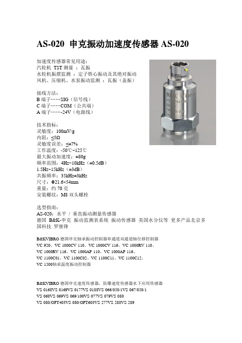
AS-020 申克振动加速度传感器AS-020加速度传感器常见用途:汽轮机TST测量:瓦振水轮机振摆监测:定子铁心振动及其绝对振动风机、压缩机、水泵振动监测:瓦振(盖振)接线方法:B端子……SIG(信号线)C端子……COM(公共端)A端子……-24V(电源线)技术指标:灵敏度:100mV/g内阻:≤5Ω灵敏度误差:≤±7%工作温度:-50℃~125℃最大振动加速度:±80g频率范围:4Hz~10kHz(±0.5dB)1.5Hz~15kHz(±3dB)共振频率:35kHz±3kHz尺寸:Φ21.6×54mm重量:约70克安装螺纹:M8双头螺栓选型指南:AS-020:水平/ 垂直振动测量传感器德国B&K-申克振动监测表系统振动传感器美国水分仪等更多产品北京多国科技罗继锋B&KVIBRO德国申克轴承振动控制器单通道双通道轴位移控制器VC-920、VC-1000CV-110、VC-1000CV-116、VC-1000RV-110、VC-1000RV-116、VC-1000AP-110、VC-1000AP-116、VC-1100C01、VC-1100C02、VC-1100C11、VC-1100C12、VC-1500轴承温度振动控制器B&KVIBRO德国申克速度传感器,防爆速度传感器水下应用传感器VS-0168VS-0169VS-0177VS-0188VS-066/050/1VS-067/050/1VS-068VS-069VS-069/100VS-077VS-079VS-080VS-080/OPT403VS-080/OPT603VS-277VS-288VS-289B&KVIBRO德国申克加速度传感器AS-020AS-022AS-022/050/1AS-022/100/0AS-022/100/1AS-030AS-062/050/0AS-062/050/1AS-062/100/0AS-062/100/1AS-062/T1/050/0AS-062/T1/050/1AS-063AS-065AS-068/050/0AS-068/050/1AS-068/100/0AS-068/100/1AS-068/200/0AS-069AS-070/001AS-070/001/200AS-070/002AS-070/002/200AS-073AS-079AS-080/01防爆加速度传感器ASA-020ASA-022ASA-022/050/1ASA-022/100/0ASA-022/100/1ASA-062ASA-062/050/1ASA-062/100/1ASA-062/300/1ASA-063ASA-068/100/0ASA-068/100/1ASA-069B&KVIBRO德国申克电涡流位移传感器1.5mm量程范围IN-081/3/070/50/0IN-081/3/110/50/0IN-081/4/070/50/0IN-081/4/110/50/0IN-083/3/070/50/0IN-083/4/070/50/0IN-084/3/060/50/0IN-085/3/070/00/0IN-085/4/070/00/0IN-085/OPT.404INA-081/3/070/100/INA-081/3/070/50/0INA-081/3/110/100/INA-081/3/110/50/0INA-081/4/070/100/INA-081/4/070/50INA-081/4/110/100/INA-083/3/070/100/INA-083/3/070/50/0INA-083/4/070/100/INA-085/3/070/00/0一体化传感器,内含前置器,无需多余的前置器。
PLC在伺服角钢冲孔机上的应用课件
FATEK 值徥您信賴的品牌
Page:5
➢产品配置示意图
产品配置
FATEK 值徥您信賴的品牌
【伺服角钢冲孔机产品配置示意图】
Page:6
产品配置
➢产品配置清单说明
控制 单元 操作单元 驱动单元
执行单元
检测单元
产品类型 永宏PLC
永宏HMI 永宏伺服
气缸 油缸 传感器ቤተ መጻሕፍቲ ባይዱ
硬件明细表
产品型号 FBs-40MAT2-AC
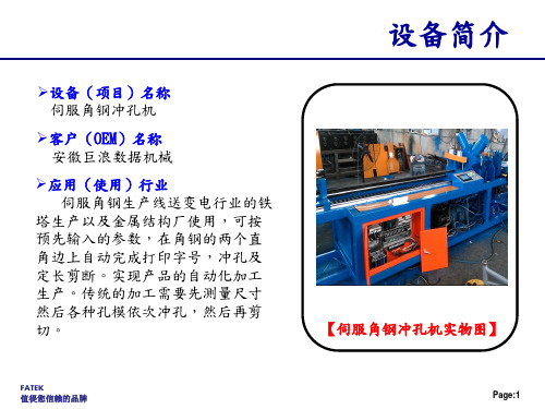
设备简介
【伺服角钢冲孔机实物图】
FATEK 值徥您信賴的品牌
Page:1
设备组成
➢设备组成说明 伺服角钢冲孔机的机械(设备)结构主要由五个模块功能组成,分
别是送料部分、孔模1部分、孔模2部分、剪切部分和尾料夹持部分。
FATEK 值徥您信賴的品牌
Page:2
➢设备组成之料仓模块组成示意图
设备组成
【送料部分组件组件】
FATEK 值徥您信賴的品牌
Page:9
技术特点&难点2
➢参数设置程序 在进行伺服角钢冲孔机的PLC整体
程序设计和规划时,参数设置程序采 用的是永宏PLC【FUN 141(伺服参数 设置)】指令来对送料伺服相关参数 进行设置;采用永宏PLC的参数设置指 令既可以完成参数设置程序的编辑, 为程序编辑和调试者提供了极大的方 便。
户的要求要有11个不同规格的产品,长度,1#孔模和2#孔模都是独立的, 不同规格的产品要在一个自动流程中连续完成。因此,将长度,1#孔模 和2#孔模都单独的作为一个比较对象,先得出各个对象相对于当前送料 长度最近的值作为送料定位的目标,送料完成进行冲剪,之后再刷新长 度和孔模的
FATEK 值徥您信賴的品牌
埃美柯阀门图册ppt幻灯片

Modicon M241 产品数据手册说明书

i s c l a im e r : T h i s d o c u m e n t a t i o n i s n o t i n t e n d e d a s a s u b s t i t u t e f o r a n d i s n o t t o b e u s e d f o r d e t e r m i n i n g s u i t a b i l i t y o r r e l i a b i l i t y o f t h e s e p r o d u c t s f o r s p e c i f i c u s e r a p p l i c a t i o n sProduct datasheetCharacteristicsTM241CE40Tcontroller M241 40 IO transistor PNP EthernetMainRange of productModicon M241Product or component type Logic controller [Us] rated supply voltage 24 V DCDiscrete input number 24 discrete input including 8 fast input conforming to IEC 61131-2 Type 1Discrete output type TransistorDiscrete output number 16 transistor including 4 fast output Discrete output voltage 24 V DC for transistor outputDiscrete output current0.1 A with Q0...Q3 terminal(s) for fast output (PTO mode)0.5 A with Q0...Q15 terminal(s) for transistor outputComplementaryDiscrete I/O number40Number of I/O expansion module 7 (local I/O architecture)14 (remote I/O architecture)Supply voltage limits 20.4...28.8 V Inrush current<= 50 APower consumption in W 32.6...40.4 W with max number of I/O expansion module Discrete input logic Sink or source Discrete input voltage 24 V Discrete input voltage type DCVoltage state1 guaranteed >= 15 V for input Current state 1 guaranteed >= 2.5 mA for input >= 5 mA for fast input Voltage state 0 guaranteed <= 5 V for input Current state 0 guaranteed <= 1 mA for input<= 1.5 mA for fast input Discrete input current 7 mA for input10.7 mA for fast input Input impedance4.7 kOhm for input2.81 kOhm for fast inputResponse time<= 2 µs turn-on operation with I0...I7 terminal(s) for fast input<= 2 µs turn-off operation with I0...I7 terminal(s) for fast input<= 2 µs turn-on operation with Q0...Q3 terminal(s) for fast output<= 2 µs turn-off operation with Q0...Q3 terminal(s) for fast output50 µs turn-on operation with I0...I15 terminal(s) for input50 µs turn-off operation with I0...I15 terminal(s) for input<= 34 µs turn-on operation with Q0...Q15 terminal(s) for output<= 250 µs turn-off operation with Q0...Q15 terminal(s) for outputConfigurable filtering time 1 µs for fast input12 ms for fast input0 ms for input1 ms for input4 ms for input12 ms for inputDiscrete output logic Positive logic (source)Output voltage limits30 V DCCurrent per output common 2 AOutput frequency<= 20 kHz for fast output (PWM mode)<= 100 kHz for fast output (PLS mode)<= 1 kHz for outputAccuracy+/- 0.1 % at 20...100 Hz for fast output+/- 1 % at 100 Hz...1 kHz for fast outputLeakage current<= 5 µA for outputVoltage drop<= 1 VTungsten load<= 2.4 WProtection type Short-circuit and overload protection with automatic resetReverse polarity protection for fast outputShort-circuit protectionReset time10 ms automatic reset output12 s automatic reset fast outputMemory capacity8 MB for program64 MB for system memory RAMData backed up128 MB built-in flash memory for backup of user programsData storage equipment<= 32 GB SD card optionalBattery type BR2032 lithium non-rechargeable, battery life: 4 yrBackup time 2 years at 25 °CExecution time for 1 KInstruction0.3 ms for event and periodic task0.7 ms for other instructionApplication structure8 external event tasks4 cyclic master tasks3 cyclic master tasks + 1 freewheeling task8 event tasksRealtime clock WithClock drift<= 60 s/month at 25 °CPositioning functions PWM/PTO function 4 channel(s) (positioning frequency: 100 kHz)Counting input number 4 fast input (HSC mode)Control signal type A/B signal at 100 kHz for fast input (HSC mode)Pulse/Direction signal at 200 kHz for fast input (HSC mode)Single phase signal at 200 kHz for fast input (HSC mode)Integrated connection type USB port with connector mini B USB 2.0Ethernet with connector RJ45Non isolated serial link "serial 1" with connector RJ45 and interface RS232/RS485Non isolated serial link "serial 2" with connector removable screw terminal block and interface RS485 Supply Serial link supply "serial 1" at 5 V, 200 mATransmission rate 1.2...115.2 kbit/s (115.2 kbit/s by default) for bus length of 15 m - communication protocol: RS4851.2...115.2 kbit/s (115.2 kbit/s by default) for bus length of 3 m - communication protocol: RS232480 Mbit/s for bus length of 3 m - communication protocol: USB10/100 Mbit/s - communication protocol: EthernetCommunication port protocol Modbus non isolated serial link with master/slave methodPort Ethernet 1 - 10BASE-T/100BASE-TX port with copper cable supportCommunication service FDRDownloadingIEC VAR ACCESSMonitoringNGVLProgrammingUpdating firmwareSMS notificationsDHCP server (via TM4 Ethernet switch network module)DHCP client (embedded Ethernet port)SNMP client/serverFTP client/serverSQL clientSend email from the controller based on TCP/UDP libraryModbus TCP client I/O scannerEthernet/IP originator I/O scanner (embedded Ethernet port)Ethernet/IP target, Modbus TCP server and Modbus TCP slaveLocal signalling 1 LED green for SD card access (SD)1 LED red for BAT1 LED green for SL11 LED green for SL21 LED per channel green for I/O state1 LED red for I/O error (I/O)1 LED red for bus fault on TM4 (TM4)1 LED green for Ethernet port activity1 LED red for module error (ERR)1 LED green for PWR1 LED green for RUNElectrical connection Removable screw terminal block for inputs and outputs (pitch 5.08 mm)Removable screw terminal block for connecting the 24 V DC power supply (pitch 5.08 mm) Cable length<= 50 m unshielded cable for input<= 10 m shielded cable for fast input<= 3 m shielded cable for fast output<= 50 m unshielded cable for outputInsulation500 V AC between fast input and internal logicNon-insulated between inputs500 V AC between output and internal logic500 V AC between fast output and internal logicNon-insulated between outputs500 V AC between input and internal logic500 V AC between output groups500 V AC between supply and internal logicNon-insulated between supply and groundMarking CESurge withstand 1 kV for power lines (DC) in common mode conforming to EN/IEC 61000-4-51 kV for shielded cable in common mode conforming to EN/IEC 61000-4-50.5 kV for power lines (DC) in differential mode conforming to EN/IEC 61000-4-51 kV for relay output in differential mode conforming to EN/IEC 61000-4-51 kV for input in common mode conforming to EN/IEC 61000-4-51 kV for transistor output in common mode conforming to EN/IEC 61000-4-5Web services Web serverMaximum number of connections8 connection(s) for Modbus server8 connection(s) for SoMachine protocol10 connection(s) for web server4 connection(s) for FTP server16 connection(s) for Ethernet/IP target8 connection(s) for Modbus clientNumber of slave16 Ethernet/IP64 Modbus TCPCycle time10 ms 16 Ethernet/IP64 ms 64 Modbus TCPMounting support Top hat type TH35-15 rail conforming to IEC 60715Top hat type TH35-7.5 rail conforming to IEC 60715Plate or panel with fixing kitHeight90 mmDepth95 mmWidth190 mmProduct weight0.62 kgEnvironmentStandards CSA C22.2 No 142ANSI/ISA 12-12-01UL 1604CSA C22.2 No 213EN/IEC 61131-2 : 2007Marine specification (LR, ABS, DNV, GL)UL 508Product certificationsCSA cULus RCMIACS E10Resistance to electrostatic discharge 4 kV on contact conforming to EN/IEC 61000-4-28 kV in air conforming to EN/IEC 61000-4-2Resistance to electromagnetic fields10 V/m (80 MHz...1 GHz) conforming to EN/IEC 61000-4-33 V/m (1.4 GHz...2 GHz) conforming to EN/IEC 61000-4-31 V/m (2 GHz...3 GHz) conforming to EN/IEC 61000-4-3Resistance to fast transients2 kV for power lines conforming to EN/IEC 61000-4-41 kV for Ethernet line conforming to EN/IEC 61000-4-41 kV for serial link conforming to EN/IEC 61000-4-41 kV for input conforming to EN/IEC 61000-4-41 kV for transistor output conforming to EN/IEC 61000-4-4Resistance to conducted disturbances,induced by radio frequency fields10 V (0.15...80 MHz) conforming to EN/IEC 61000-4-63 V (0.1...80 MHz) conforming to Marine specification (LR, ABS, DNV, GL)10 V (spot frequency (2, 3, 4, 6.2, 8.2, 12.6, 16.5, 18.8, 22, 25 MHz)) conforming to Marine specification (LR, ABS, DNV, GL)Electromagnetic emissionConducted emissions, test level: 120...69 dBµV/m QP, condition of test: power lines (radio frequency:10...150 kHz) conforming to EN/IEC 55011Conducted emissions, test level: 79...63 dBμV/m QP, condition of test: power lines (radio frequency:150 kHz...1.5 MHz) conforming to EN/IEC 55011Conducted emissions, test level: 63 dBμV/m QP, condition of test: power lines (radio frequency:1.5...30 MHz) conforming to EN/IEC 55011Radiated emissions, test level: 40 dBμV/m QP with class A (radio frequency: 30...230 MHz)conforming to EN/IEC 55011Radiated emissions, test level: 47 dBμV/m QP with class A (radio frequency: 230 MHz...1 GHz)conforming to EN/IEC 55011Immunity to microbreaks10 msAmbient air temperature for operation -10...55 °C for horizontal installation -10...50 °C for vertical installation Ambient air temperature for storage -25...70 °CRelative humidity 10...95 % without condensation in operation 10...95 % without condensation in storage IP degree of protection IP20 with protective cover in place Pollution degree 2Operating altitude 0...2000 m Storage altitude 0...3000 mVibration resistance3.5 mm (vibration frequency: 5...8.4 Hz) on symmetrical rail 3 gn (vibration frequency: 8.4...150 Hz) on symmetrical rail 3.5 mm (vibration frequency:5...8.4 Hz) on panel mounting 3 gn (vibration frequency: 8.4...150 Hz) on panel mounting Shock resistance15 gn for 11 msOffer SustainabilitySustainable offer status Green Premium productRoHS (date code: YYWW)Compliant - since 1330 - Schneider Electric declaration of conformity Schneider Electric declaration of conformity REAChReference not containing SVHC above the threshold Reference not containing SVHC above the threshold Product environmental profileAvailableProduct environmental Product end of life instructionsAvailableEnd of life manualDimensions Drawings DimensionsClearanceMounting PositionAcceptable MountingNOTE: Expansion modules must be mounted above the logic controller.Incorrect MountingDirect Mounting On a Panel Surface Mounting Hole LayoutDigital InputsWiring Diagram(*) :Type T fuse(1) :The COM0, COM1 and COM2 terminals are not connected internally (A) :Sink wiring (positive logic)(B) :Source wiring (negative logic)Fast Input Wiring (I0...I7)Fast Transistor OutputsWiring Diagram(*) :Type T fuse(1)The V0+, V1+, V2+ and V3+ terminals are not connected internally.(2)The V0-, V1-, V2- and V3- terminals are not connected internally.Transistor OutputsWiring Diagram(*) :Type T fuse(1) :The V1+, V2+ and V3+ terminals are not connected internally.(2) :The V1–, V2– and V3– terminals are not connected internally.USB Mini-B ConnectionEthernet Connection to a PC。
科肯H200A系列用户手册中文版

3.1 机械安装................................................................................................................................................... - 13 3.2 电气安装................................................................................................................................................... - 14 -H200ຫໍສະໝຸດ 用户手册前言前言
感谢您购买 H200A 系列变频器!
本使用说明书介绍了如何正确使用 H200A 系列变频器。在使用(安装、运行、维护、检 查等)前,请务必认真阅读本使用说明书。另外,请在理解产品的安全注意事项后再使用该产 品。
H200A 系列变频器,不仅兼容 H200 的绝大部分功能,以配合客户的使用习惯,还进行了 部分的优化升级,在功能、性能、易用性等方面均有提高。
本手册提供给使用者选型、安装、参数设置、现场调试、故障诊断及日常保养与维护的相 关注意事项及指导。为正确使用本系列变频器,请事先认真阅读本手册,并请妥善保存以备后 用。设备配套客户请将此手册随设备发给最终用户。
- 1、下载文档前请自行甄别文档内容的完整性,平台不提供额外的编辑、内容补充、找答案等附加服务。
- 2、"仅部分预览"的文档,不可在线预览部分如存在完整性等问题,可反馈申请退款(可完整预览的文档不适用该条件!)。
- 3、如文档侵犯您的权益,请联系客服反馈,我们会尽快为您处理(人工客服工作时间:9:00-18:30)。
元器件交易网
PACKING & LABEL SPECIFICATIONS
ACSA02-41CGKWA-F01
SPEC NO: DSAG0259 APPROVED: WYNEC
REV NO: V.3 CHECKED: Joe Lee
DATE: JUN/18/2007 DRAWN: Y.L.LI
WHITE DIFFUSED
4700
Electrical / Optical Characteristics at TA=25°C
Symbol λpeak λD [1] Δλ1/2 C VF [2] IR Parameter Peak Wavelength Dominant Wavelength Spectral Line Half-width Capacitance Forward Voltage Reverse Current Device Green Green Green Green Green Green Typ. 574 570 20 15 2.1 2.5 10 Max. Units nm nm nm pF V uA Test Conditions IF=20mA IF=20mA IF=20mA VF=0V;f=1MHz IF=20mA VR=5V
Note: 1. 1/10 Duty Cycle, 0.1ms Pulse Width.
Green 75 30 150 5 -40°C To +85°C
Units mW mA mA V
SPEC NO: DSAG0259 APPROVED: WYNEC
REV NO: V.3 CHECKED: Joe Lee
Part No. Dice Lens Type Iv (ucd) [1] @ 10mA Min. ACSA02-41CGKWA-F01 Green (InGaAlP)
Note: 1. Luminous intensity/ luminous Flux: +/-15%.
Description
Typ. 26000 Common Anode, Rt. Hand Decimal.
DATE: JUN/18/2007 DRAWN: Y.L.LI
PAGE: 2 OF 5 ERP: 1351000429
元器件交易网
Green
ACSA02-41CGKWA-F01
SPEC NO: DSAG0259 APPROVED: WYNEC
REV NO: V.3 CHECKED: Joe Lee
元器件交易网
SURFACE MOUNT DISPLAY
Part Number: ACSA02-41CGKWA-F01 Green
Features
0.2INCH DIGIT HEIGHT. LOW CURRENT OPERATION. EXCELLENT CHARACTER APPEARANCE. I.C. COMPATIBLE MECHANICALLY RUGGED. GRAY FACE,WHITE SEGMENT. PACKAGE : 650PCS / REEL. MOISTURE SENSITIVITY LEVEL : LEVEL 4. RoHS COMPLIANT.
DATE: JUN/18/2007 DRAWN: Y.L.LI
PAGE: 3 OF 5 ERP: 1351000429
元01
Recommended Soldering Pattern (Units : mm; Tolerance: ± 0.15)
Reel Dimension
Tape Specifications (Units : mm)
SPEC NO: DSAG0259 APPROVED: WYNEC
REV NO: V.3 CHECKED: Joe Lee
DATE: JUN/18/2007 DRAWN: Y.L.LI
PAGE: 4 OF 5 ERP: 1351000429
Notes: 1.Wavelength: +/-1nm. 2. Forward Voltage: +/-0.1V.
Absolute Maximum Ratings at TA=25°C
Parameter Power dissipation DC Forward Current Peak Forward Current [1] Reverse Voltage Operating / Storage Temperature
SPEC NO: DSAG0259 APPROVED: WYNEC
REV NO: V.3 CHECKED: Joe Lee
DATE: JUN/18/2007 DRAWN: Y.L.LI
PAGE: 1 OF 5 ERP: 1351000429
元器件交易网
Selection Guide
Description
The Green source color devices are made with InGaAlP on GaAs substrate Light Emitting Diode.
Package Dimensions& Internal Circuit Diagram
Notes: 1. All dimensions are in millimeters (inches), Tolerance is ±0.25(0.01")unless otherwise noted. 2. Specifications are subject to change without notice. 3. The gap between the reflector and PCB shall not exceed 0.25mm.
PAGE: 5 OF 5 ERP: 1351000429