MBRB2040CT中文资料
MBR2060CT;MBR2050CT;MBR2045CT;MBR2035CT;中文规格书,Datasheet资料
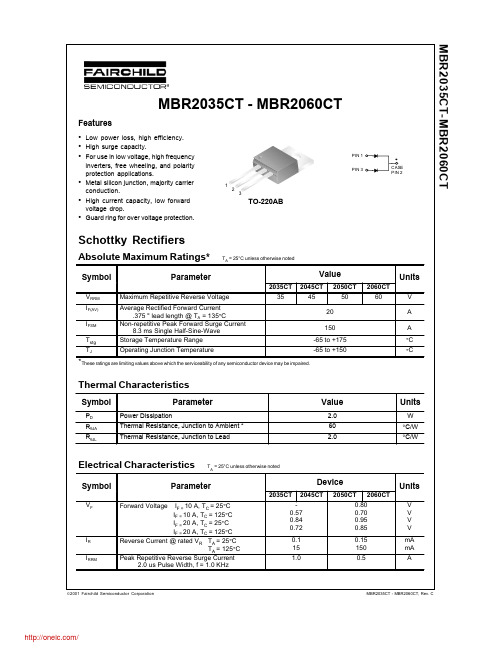
MBR2035CT - MBR2060CT
Features • • • • • •
Low power loss, high efficiency. High surge capacity. For use in low voltage, high frequency inverters, free wheeling, and polarity protection applications. Metal silicon junction, majority carrier conduction. High current capacity, low forward voltage drop. Guard ring for over voltage protection.
20
150 125 100 75 50 25 0
16
12
SINGLE PHASE HALF WAVE 60HZ RESISTIVE OR INDUCTIVE LOAD .375" (9.00mm) LOAD LENGTHS
8
4
0
0
25
50 75 100 125 Ambient Temperature [ºC]
Figure 3. Forward Voltage Characteristics
Figure 4. Reverse Current vs Reverse Voltage
2000 1000 500
MBR2050CT-MBR2060CT MBR2035CT-MBR2045CT
Transient Thermal Impedance [ºC/W]
Thermal Characteristics
MBR2045CT中文资料
vF 0.57 0.72 0.84 iR 15 0.1 15 0.1 0.57 0.72 0.84
Volts
mA
元器件交易网
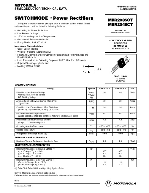
MOTOROLA
SEMICONDUCTOR TECHNICAL DATA
Order this document by MBR2035CT/D
SWITCHMODE™ Power Rectifiers
. . . using the Schottky Barrier principle with a platinum barrier metal. These state–of–the–art devices have the following features: • • • • • Guardring for Stress Protection Low Forward Voltage 150°C Operating Junction Temperature Guaranteed Reverse Avalanche Epoxy Meets UL94, VO at 1/8″
TJ = 150°C
AV
60
+ 20, 10, 5
80 100 120 140 160
16
20
24
28
32
IF(AV), AVERAGE FORWARD CURRENT (AMPS)
TA, AMBIENT TEMPERATURE (°C)
Figure 7. Forward Power Dissipation
MBR30H100CT中文资料
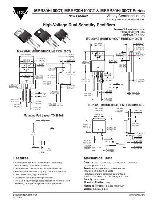
MBR30H100CT , MBRF30H100CT & MBRB30H100CT SeriesVishay Semiconductorsformerly General SemiconductorDocument Number New ProductReverse Voltage 90 to 100VForward Current 30A Maximum T J 175°CMounting Pad Layout TO-263ABITO-220AB (MBRF30H90CT, MBRF30H100CT)(MBR30H90CT, MBR30H100CT)TO-263AB (MBRB30H90CT, MBRB30H100CT)Features• Plastic package has Underwriters Laboratory Flammability Classification 94V-0• Dual rectifier construction, positive center tap • Metal silicon junction, majority carrier conduction • Low power loss, high efficiency• Guardring for overvoltage protection• For use in low voltage, high frequency inverters, free wheeling, and polarity protection applicationsMechanical DataCase:JEDEC TO-220AB, ITO-220AB & TO-263AB molded plastic bodyTerminals:Plated leads, solderable per MIL-STD-750, Method 2026High temperature soldering guaranteed: 250°C/10 seconds, 0.25" (6.35mm) from case Polarity:As markedMounting Position: AnyMounting Torque:10 in-lbs maximum Weight:0.08oz., 2.24gMBR30H100CT , MBRF30H100CT & MBRB30H100CT SeriesVishay Semiconductorsformerly General Semiconductor Document Number 88791Maximum Ratings (TC= 25°C unless otherwise noted)ParameterSymbol MBR30H90CTMBR30H100CTUnit Maximum repetitive peak reverse voltage V RRM 90100V Working peak reverse voltage V RWM 90100V Maximum DC blocking voltageV DC 90100V Maximum average forward rectified current Total device 30(see fig. 1)Per leg I F(AV)15A Peak forward surge current8.3ms single half sine-wave superimposed I FSM 275A on rated load (JEDEC Method) per legPeak repetitive reverse current per leg at t p = 2µs, 1KH Z I RRM 1.0A Voltage rate of change (rated V R )dv/dt 10,000V/µs Operating junction and storage temperature range T J , T STG –65 to +175°C RMS Isolation voltage (MBRF type only) from terminals 4500(1)to heatsink with t = 1 second, RH ≤30%V ISOL3500(2)V1500(3)Electrical Characteristics (TC= 25°C unless otherwise noted)ParameterSymbolValue Unit at I F = 15A, T J = 25°C 0.82Maximum instantaneous at I F = 15A, T J = 125°C V F0.67Vforward voltage per leg (4)at I F = 30A, T J = 25°C 0.93at I F = 30A, T J = 125°C0.80Maximum reverse current per leg T J = 25°C 5.0µA at working peak reverse voltage (4)T J = 125°CI R6.0mAThermal Characteristics (TC= 25°C unless otherwise noted)ParameterSymbol MBR MBRF MBRB UnitTypical thermal resistance per legR θJC1.94.61.9OC/WNotes:(1) Clip mounting (on case), where lead does not overlap heatsink with 0.110” offset (2) Clip mounting (on case), where leads do overlap heatsink(3) Screw mounting with 4-40 screw, where washer diameter is ≤ 4.9 mm (0.19”)(4) Pulse test: 300µs pulse width, 1% duty cycleOrdering InformationProductCase Package CodePackage OptionMBR30H90CT - MBR30H100CT TO-220AB 45Anti-Static tube, 50/tube, 2K/carton MBRF30H90CT - MBRF30H100CT ITO-220AB 45Anti-Static tube, 50/tube, 2K/carton 3113” reel, 800/reel, 4.8K/cartonMBRB30H90CT - MBRB30H100CTTO-263AB45Anti-Static tube, 50/tube, 2K/carton81Anti-Static 13” reel, 800/reel, 4.8K/cartonMBR30H100CT , MBRF30H100CT & MBRB30H100CT SeriesVishay Semiconductorsformerly General SemiconductorDocument Number Ratings andCharacteristic Curves (T A = 25°C unless otherwise noted)100100.10.011.0J u n c t i o n C a p a c i t a n c e (p F )110100100100000.110Reverse Voltage (V)t, Pulse Duration (sec.)I F -- I n s t a n t a n e o u s F o r w a r d C u r r e n t (A )5101520253035Fig. 1 – Forward Derating CurvePer LegA v e r a g e F o r w a r d C u r r e n t (A )Fig. 2 – Maximum Non-Repetitive Peak Forward Surge Current Per Leg1000。
SBR2040CT资料
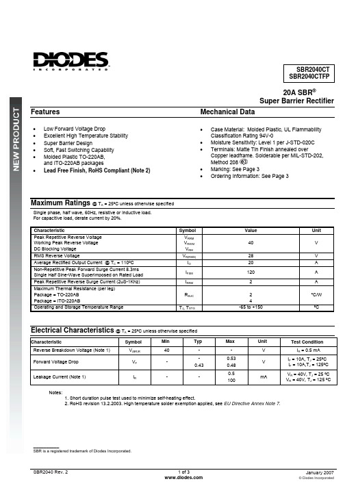
20A SBR®Super Barrier RectifierFeatures MechanicalData• Case Material: Molded Plastic, UL FlammabilityClassification Rating 94V-0• Moisture Sensitivity: Level 1 per J-STD-020C• Terminals: Matte Tin Finish annealed overCopper leadframe. Solderable per MIL-STD-202,Method 208• Marking: See Page 3• Ordering Information: See Page 3• Low Forward Voltage Drop• Excellent High Temperature Stability• Super Barrier Design• Soft, Fast Switching Capability• Molded Plastic TO-220AB,and ITO-220AB packages• Lead Free Finish, RoHS Compliant (Note 2)Maximum Ratings @ T A = 25ºC unless otherwise specifiedSingle phase, half wave, 60Hz, resistive or inductive load.For capacitive load, derate current by 20%.Characteristic SymbolValueUnit Peak Repetitive Reverse VoltageWorking Peak Reverse VoltageDC Blocking VoltageV RRMV RWMV RM40 VRMS Reverse Voltage V R(RMS)28 VAverage Rectified Output Current @ T C = 110ºC I O20 ANon-Repetitive Peak Forward Surge Current 8.3msSingle Half Sine-Wave Superimposed on Rated LoadI FSM120 APeak Repetitive Reverse Surge Current (2uS-1Khz) I RRM 2 AMaximum Thermal Resistance (per leg)Package = TO-220ABPackage = ITO-220ABRӨJC 24°C/WOperating and Storage Temperature Range T J, T STG-65 to +150 ºCElectrical Characteristics@ T A = 25ºC unless otherwise specifiedCharacteristic SymbolMin Typ Max Unit Test ConditionReverse Breakdown Voltage (Note 1) V(BR)R40 - - V I R = 0.5 mAForward Voltage Drop V F--0.430.530.48VI F = 10A, T J = 25ºCI F = 10A,T J = 125ºCLeakage Current (Note 1) I R- -0.5100mAV R = 40V, T J= 25 ºCV R = 40V, T J = 125 ºCNotes:1. Short duration pulse test used to minimize self-heating effect.2. RoHS revision 13.2.2003. High temperature solder exemption applied, see EU Directive Annex Note 7.__________SBR is a registered trademark of Diodes Incorporated.Package Outline DrawingsITO-220ABTO-220ABTO-220ABDIM. MIN. MAX.A 4.47 4.67 b 0.71 0.91 b1 1.17 1.37 c 0.31 0.53 D 14.65 15.35 D1 8.50 8.90 E 10.01 10.31 e 2.54 typ e1 4.98 5.18 F 1.17 1.37 J1 2.52 2.82 L 13.4013.80 L1 3.56 3.96 ØP 3.735 3.935 Q 2.59 2.89All Dimensions in MillimetersITO-220ABDIM. MIN. MAX.A 4.30 4.70b 0.50 0.75 b1 1.10 1.35 b2 1.50 1.75c 0.50 0.75 D 14.80 15.20 E 9.96 10.36 e 2.54 typ F 2.80 3.20 J1 2.50 2.90 L 12.80 13.60 L1 1.70 1.90 ØP 3.50 typ Q 2.70 typAll Dimensions in MillimetersMarking, Polarity, Weight & Ordering InformationSBR2040CT SBR2040CTFP Case StyleTO-220AB ITO-220ABtAnodeCommonCathode AnodePolarityCasetAnodeCommonCathode AnodeMarking2.1g 1.9gWeightOrderingInformationSBR2040CT SBR2040CTFP50 pieces/tube50 pieces/tubeYY = Last two digits of year, ex = 06 = 2006Date CodeWW = Week (01-52)Other MarkingInformationA = Foundry CodeB = Assembly CodeIMPORTANT NOTICEDiodes Incorporated and its subsidiaries reserve the right to make modifications, enhancements, improvements, corrections or other changeswithout further notice to any product herein. Diodes Incorporated does not assume any liability arising out of the application or use of any productdescribed herein; neither does it convey any license under its patent rights, nor the rights of others. The user of products in such applications shallassume all risks of such use and will agree to hold Diodes Incorporated and all the companies whose products are represented on our website,harmless against all damages.LIFE SUPPORTDiodes Incorporated products are not authorized for use as critical components in life support devices or systems without the expressed writtenapproval of the President of Diodes Incorporated.。
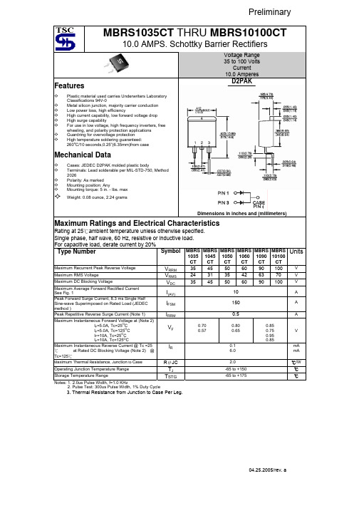
MBRS10100CT资料
100
0.70 0.57 0.80 0.65 0.1 6.0 2.0 -65 to +150 -65 to +175 0.85 0.75 0.95 0.85
V mA mA ℃/W ℃ ℃
TSTG
TJ
3. Thermal Resistance from Junction to Case Per Leg.
04.25.2005/rev. a
元器件交易网
RATINGS AND CHARACTERISTIC CURVES (MBRS1035CT THRU MBRS10100CT)
FIG.1- FORWARD CURRENT DERATING CURVE
5.0
180
FIG.2- MAXIMUM NON-REPETITIVE FORWARD SURGE CURRENT PER LEG
Plastic material used carries Underwriters Laboratory Classifications 94V-0 Metal silicon junction, majority carrier conduction Low power loss, high efficiency High current capability, low forward voltage drop High surge capability For use in low voltage, high frequency inverters, free wheeling, and polarity protection applications Guardring for overvoltage protection High temperature soldering guaranteed: 260oC/10 seconds,0.25”(6.35mm)from case
MBR40200FCT丨MBR40200CT全塑封半塑封ASEMI半导体选型参数

编辑:DD摘要:ASEMI肖特基二极管MBR40100FCT全塑封封装和铁头封装哪种性能比较好?这两种封装各有它的有点?不着急,接下来,就由ASEMI工程就为大家详细介绍这两款封装的区别及优点台湾ASEMI肖特基二极管MBR40200FCT全部采用:进口高性能俄罗斯Mikron扩散高抗击芯片,内置130Mil大规格整流芯片;确保平均最大输出40A 的电流;反向耐压值达到100V;通俗的来讲,MBR40200FCT可以通过正向40A的电流,而反向可以承受100V的电压。
MBR40200FCT是一款常规型肖特基二极管,广泛应用于高频电源等领域。
电性参数方面都被大家广为熟知。
那么有关于它的封装问题,又有多少朋友知道呢?MBR40200FCT既有全塑封封装又有铁头封装,这也是工程或者采购朋友们一直困惑的问题,到底应该采购哪种比较好呢?不着急,接下来,就由ASEMI工程就为大家详细介绍这两款封装的区别及优点。
ASEMI肖特基二极管MBR40200FCT-用全塑封装绝缘性更好我们经常所说采用塑封或者全塑封,就是指MBR40200FCT肖特基二极管内部框架、芯片、焊片等等电路全部被一体包封住,与外界隔绝。
它所采用的材料是环氧树脂,这种高级环氧材料具有非常好的抗热性,防氧化性及绝缘性都非常好。
我们知道MBR40200FCT应用领域多为电源高频整流环节,所以对安全性要求比较高,需要拥有很好绝缘性来避免电路短路等故障发生。
正是这样,采用全塑封装的能有效避免内部电路与外界接触,更好的保护电路安全。
ASEMI肖特基二极管MBR40200FCT-用铁头封装散热性表现更佳这款肖特基二极管除了有采用为保障电路安全的全塑封装外,还有另外一种封装,那就是为解决散热性问题的铁头封装。
采用铁头封装的型号打标方式为MBR40200CT与全塑封装相区别。
这种封装能大幅提升电源的有效散热效率,针对发热严重或者对散热要求高的电路非常适用。
综上所述,就是MBR40200全塑封与铁头的详细介绍了,不知工程及采购朋友掌握了没有呢?仅供参考,希望对大家在以后应用货采购上有所帮助。
MBR20H100CT中文资料

MBR20H100CT , MBRF20H100CT & MBRB20H100CT SeriesVishay Semiconductorsformerly General SemiconductorDocument Number New ProductCase:JEDEC TO-220AB, ITO-220AB, TO-263AB & TO-262AA molded plastic bodyTerminals:Plated leads, solderable per MIL-STD-750, Method 2026High temperature soldering guaranteed:250°C/10 seconds, 0.25" (6.35mm) from case (TO-220AB,ITO-220AB & TO-252AA) at terminals (TO-236AB)Polarity:As marked Mounting Position: Any Mounting Torque:10 in-lbs maximum Weight:0.08 oz., 2.24 g• Plastic package has Underwriters Laboratory Flammability Classification 94V-0• Dual rectifier construction, positive center tap • Metal silicon junction, majority carrier conduction • Low power loss, high efficiency• Guardring for overvoltage protection• For use in low voltage, high frequency inverters, free wheeling, and polarity protection applicationsMBR20H100CT , MBRF20H100CT & MBRB20H100CT SeriesVishay Semiconductorsformerly General Semiconductor Document Number 88673Maximum Ratings (TC= 25°C unless otherwise noted)ParameterSymbol MBR20H90CTMBR20H100CTUnit Maximum repetitive peak reverse voltage V RRM 90100V Working peak reverse voltage V RWM 90100V Maximum DC blocking voltageV DC90100V Maximum average forward rectified current Total device20Per legI F(AV)10A Peak forward surge current8.3ms single half sine-wave superimposed I FSM 250A on rated load (JEDEC Method) per legPeak repetitive reverse current per leg at t p = 2µs, 1KH Z I RRM 1.0A Voltage rate of change (rated V R )dv/dt 10,000V/µs Operating junction and storage temperature range T J , T STG –65 to +175°C RMS Isolation voltage (MBRF type only) from terminals 4500(1)to heatsink with t = 1 second, RH ≤30%V ISOL3500(2)V1500 (3)Electrical Characteristics (TC= 25°C unless otherwise noted)ParameterSymbolValue UnitMaximum instantaneous I F = 10A,T C = 25°C 0.77forward voltage per leg at (4):I F = 10A,T C = 125°C 0.64I F = 20A,T C = 25°C V F 0.88V I F = 20A,T C = 125°C 0.73Maximum reverse current per leg T J = 25°C 4.5µA at working peak reverse voltageT J = 125°CI R6.0mAThermal Characteristics (TC= 25°C unless otherwise noted)ParameterSymbol MBR MBRF MBRB Unit Typical thermal resistance per legR ΘJC2.05.82.0°C/WNotes:(1) Clip mounting (on case), where lead does not overlap heatsink with 0.110” offset (2) Clip mounting (on case), where leads do overlap heatsink(3) Screw mounting with 4-40 screw, where washer diameter is ≤ 4.9 mm (0.19”)(4) Pulse test: 300µs pulse width, 1% duty cycleOrdering InformationProductCase Package CodePackage OptionMBR20H90CT - MBR20H100CT TO-220AB 45Anti-Static tube, 50/tube, 2K/carton MBRF20H90CT - MBRF20H100CT ITO-220AB 45Anti-Static tube, 50/tube, 2K/carton 3113” reel, 800/reel, 4.8K/cartonMBRB20H90CT - MBRB20H100CTTO-263AB45Anti-Static tube, 50/tube, 2K/carton81Anti-Static 13” reel, 800/reel, 4.8K/cartonMBR20H100CT , MBRF20H100CT & MBRB20H100CT SeriesVishay Semiconductorsformerly General SemiconductorDocument Number Ratings andCharacteristic Curves per leg (TA= 25°C unless otherwise noted)481220160.11101001000Fig. 1 — Forward Current Derating CurveFig. 2 — Maximum Non-Repetitive PeakForward Surge Current Per Leg0.010.1110。
SB2040CT中文资料
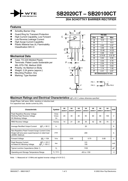
SB2020CT – SB20100CT20A SCHOTTKY BARRIER RECTIFIERSingle Phase, half wave, 60Hz, resistive or inductive load.For capacitive load, derate current by 20%.Characteristic Symbol SB2020CTSB2030CTSB2040CTSB2050CTSB2060CTSB2080CTSB20100CTUnitPeak Repetitive Reverse Voltage Working Peak Reverse Voltage DC Blocking Voltage V RRMV RWMV R203040506080100VRMS Reverse Voltage V R(RMS)14212835425670V Average Rectified Output Current @T C = 95°C I O20A Non-Repetitive Peak Forward Surge Current 8.3msSingle half sine-wave superimposed on rated load(JEDEC Method)I FSM200A Forward Voltage @I F = 10A V FM0.550.750.85VPeak Reverse Current @T A = 25°C At Rated DC Blocking Voltage @T A = 100°C I RM0.5100mATypical Junction Capacitance (Note 1)C j1100pF Operating and Storage Temperature Range T j, T STG-65 to +150°C Note: 1. Measured at 1.0 MHz and applied reverse voltage of 4.0V D.C.WTEI ,A V E R A G E O U T P U T C U R R E N T (A )(A V )04812162010406080100120140150T , CASE TEMPERATURE (ºC)Fig.1Forward Current Derating CurveC100100020000.1 1.010100C ,C A P A C I T A N C E (p F )j V ,REVERSE VOL TAGE (V)Fig.4T ypical Junction CapacitanceR 050100150200250110100I , P E A K F O R W A R D S U R G E C U R R E N T (A )F S M NUMBER OF CYCLES AT 60HzFig. 3 Maximum Non-Repetitive P eak Fwd Surge Current11020400.51.01.52.02.5I ,N S T A N T A N E O U S F O R W A R D C U R R E N T (A )F V ,INSTANTANEOUS FORWARD VOLTAGE (V)Fig.2T ypical Forward CharacteristicsFORDERING INFORMATIONProduct No.Package TypeShipping QuantitySB2020CT TO-22050 Units/Tube SB2030CT TO-22050 Units/Tube SB2040CT TO-22050 Units/Tube SB2050CT TO-22050 Units/Tube SB2060CT TO-22050 Units/Tube SB2080CT TO-22050 Units/Tube SB20100CTTO-22050 Units/TubeShipping quantity given is for minimum packing quantity only. For minimum orderquantity, please consult the Sales Department.Won-Top Electronics Co., Ltd (WTE) has checked all information carefully and believes it to be correct and accurate. However, WTE cannot assume any responsibility for inaccuracies. Furthermore, this information does not give the purchaser of semiconductor devices any license under patent rights to manufacturer. WTE reserves the right to change any or all information herein without further notice.WARNING : DO NOT USE IN LIFE SUPPORT EQUIPMENT. WTE power semiconductor products are not authorized for use as critical components in life support devices or systems without the express written approval.We power your everyday.Won-Top Electronics Co., Ltd.No. 44 Yu Kang North 3rd Road, Chine Chen Dist., Kaohsiung, Taiwan Phone: 886-7-822-5408 or 886-7-822-5410Fax: 886-7-822-5417Email: sales@Internet: 。
- 1、下载文档前请自行甄别文档内容的完整性,平台不提供额外的编辑、内容补充、找答案等附加服务。
- 2、"仅部分预览"的文档,不可在线预览部分如存在完整性等问题,可反馈申请退款(可完整预览的文档不适用该条件!)。
- 3、如文档侵犯您的权益,请联系客服反馈,我们会尽快为您处理(人工客服工作时间:9:00-18:30)。
MBRB2020CT THRU MBRB20100CT
20 Amp
Schottky
Meatl of Silicon Rectifier, Majority Conducton Guard ring for transient protection Low Forward Voltage Drop High Current Capability, High Efficiency Low Power Loss
10 Amps
2
MCC
Figure 2 Typical Reverse Characteristics
100 Volts
125 150
175
Volts Instantaneous Forward Current - Amperesversus Instantaneous Forward Voltage - Volts Figure 3 Forward Derating Curve 20
VF
.84V .80V .85V
IFM = 20A; IFM =10 A TA = 25°C
DIM A B C D E. G H J K S V
MAX 9.65 10.29 4.83 0.89 1.40 BSC 2.79 0.64 2.79 15.88 1.40
NOTE
IR
0.1mA 0.15mA
TA = 25°C
Barrier Rectifier 20 to 100 Volts
D2-PACK
S
Maximum Ratings
• • MCC Catalog Number MBRB2020CT MBRB2030CT MBRB2035CT MBRB2040CT MBRB2045CT MBRB2060CT MBRB2080CT MBRB20100CT
元器件交易网
MCC
Features
• • • • •
omponents 21201 Itasca Street Chatsworth !"# $
% !"#
Operating Temperature: -55 °C to +150°C Storage Temperature: -55°C to +150°C Maximum Recurrent Peak Reverse Voltage 20V 30V 35V 40V 45V 60V 80V 100V Maximum RMS Voltage 14V 21V 24.5V 28V 31.5V 42V 56V 70V Maximum DC Blocking Voltage 20V 30V 35V 40V 45V 60V 80V 100V
*Pulse Test: Pulse Width 300 µsec, Duty Cycle 1%
元器件交易网
MBRB2020CT thru MBRB20100CT
Figure 1 Typical Forward Characteristics 100 60 40 20 2020CT-1645CT 10 6 4 2 25°C Amps 1 .6 .4 .2 .1 .06 .04 .02 .01 .2 .3 .4 .5 .6 .7 .8 2080-20100CT .2 TJ=25°C mAmps .1 .06 .04 .02 .01 .006 .004 4 .002 .001 20 50 75 2060CT 10 6 4 2 1 .6 .4
A 1 G 2 3 D 4
V
B
H E K
C
Electrical Characteristics @ 25°C Unless Otherwise Specified
Average Forward Current Peak Forward Surge Current Maximum Instantaneous Forward Voltage 2020CT-2045CT 2060CT 2080CT-20100 Maximum DC Reverse Current At Rated DC Blocking Voltage 2020CT-2045CT 2060CT-20100CT IF(AV) IFSM 20 A 150A TA = 125°C 8.3ms, half sine
Hale Waihona Puke Instantaneous Reverse Leakage Current - MicroAmperes versus Percent Of Rated Peak Reverse Voltage - Volts
Figure 4 Peak Forward Surge Current 150
18 125 14 100 75 Amps 8 25 5 Single Phase, Half Wave 60Hz Resistive or Inductive Load 0 0 25 50 75 °C Average Forward Rectified Current - Amperes versus Ambient Temperature - °C 100 125 150 0 1 4 6 8 10 Cycles Peak Forward Surge Current - Amperesversus Number Of Cycles At 60Hz - Cycles 20 40 60 80 100 50
J
DIMENSIONS INCHES MIN MAX .340 .380 .380 .405 .160 .190 .020 .035 .45 .055 .100 BSC .080 .110 .018 .025 .090 .110 .575 .62 5 .045 .055 MM MIN 8.64 9.65 4.06 .051 1.14 2.54 2.03 0.46 2.29 14.60 1.14