PowerSA-104t通信管理机用户手册
PowerSA-M测控单元用户手册
PowerSA-M综合测控单元用户手册1、概述PowerSA-M通信装置是北京六所和瑞科技发展有限公司以引进国际领先核心技术为基础研发的具有强大测控、处理和通信能力的综合单元;作为RTU、分布式测控单元能专业应用于电力自动化、及其他工业自动化系统现场测量、控制与数据处理和转发;PowerSA-M装置全模块化的I/O板卡和软件功能设计,确保了方便地定制各种不同用户需求的应用功能。
PowerSA-M测控单元具备多个以太网和串行通信的接口,可接入任何监控系统;可综合采集和处理各种保护装置、智能设备的I/O数据。
基于当代技术水平的开放式平台,保证了各种层次和级别的自动化系统方案的设计以及将来的扩充。
PowerSA-M综合处理单元和PowerSA-C为基础的PowerSA系列产品为旧站改造和新站建设提供优异性价比的方便灵活的解决方案。
其主要特点如下:采用先进可靠的软硬件技术:VxWorks 嵌入式操作系统;32位高速嵌入式CPU芯片,配备大容量的RAM、和FlashROM;快速以太网通信接口。
◆软件、硬件双模块化的设计,能为用户以间隔测控为单位量身定制I/O数量和软件功能。
◆灵活的组网路由功能,实现各种拓扑体系的多装置(1-250节点)分布式系统;◆多接口配置,支持国际标准通信规约以及流行规约和多种通信接入方式。
◆提供单元内部和跨单元间的联闭锁控制,全站联闭锁。
◆综合性组态工具软件tBE,提供统一、强大和方便的参数组态、设备诊断和监视的手段。
◆高标准的抗干扰性,充分的电磁兼容设计考虑:I/O板间互为独立,板内多级隔离、表面贴技术、多层印刷电路板技术、内部连接采用牢固插接器。
2.功能➢模拟量采集功能:装置可同时采集处理交流模拟量和直流模拟量。
交流采样包括以灵活配置的二元件法和三元件法计算U、I、P、Q、COS、Hz、θ等;直流采样包括电压型、电流型等。
传输方式包括越死区变化报告、定时全数据报告。
➢数字量采集功能:装置可采集处理单接点、双接点状态量,SOE等。
国际版104功能和使用说明
国际版104功能和使⽤说明国际版104功能和使⽤说明1 概要IEC104协议是⼀种基于以太⽹⽅式与调度系统通讯的协议,它在以太⽹TCP/IP 链路上传输IEC-870-5-101协议的ASDU 应⽤服务数据单元,实现与主站的通信。
由于变电站综合⾃动化系统需要上传的信息量越来越⼤,且变电站通讯线路的质量越来越好。
因此基于以太⽹通讯⽅式的IEC104协议也渐渐成为各级调度系统的⾸选通讯⽅式。
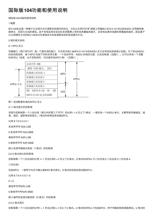
2 规约报⽂结构2.1 APCI 定义传输接⼝(⽤户到TCP)是⼀个⾯向流的接⼝,它没有为IEC 60870-5-101中的ASDU 定义任何启动或者停⽌机制。
为了检出ASDU 的启动和结束,每个APCI 包括下列的定界元素:⼀个启动字符,ASDU 的规定长度,以及控制域(见图1)。
它可以传送⼀个完整的APDU(或者,出于控制⽬的,仅仅是传送APCI 域)(见图1)。
图 1 远动配套标准的APDU 定义2.1 I 格式报⽂的控制域该报⽂控制域第⼀个⼋位位组(报⽂中的第三个字节)的⽐特1 = 0 定义了I 格式,⼀般包含⼀个ASDU 单元,主要⽤来传输遥信、遥测、遥控、遥脉等信息报⽂。
I 格式的控制信息如图2所⽰。
⽐特 8 7 6 5 4 3 2 1发送序列号 N(S) LSB0 发送序列号 N(S) MSB接收序列号 N(R) LSB0 接收序列号 N(R) MSB图 2 信息传输格式类型( I 格式)的控制域2.2 S 格式报⽂的控制域控制域第⼀个⼋位位组的⽐特 1= 1 并且⽐特2 = 0 定义了S 格式。
S 格式的APDU 只⼋位位组 2 ⼋位位组 3 ⼋位位组 4⼋位位组1包括APCI,⼀般⽤于向对⽅确认接收的I 格式报⽂。
S 格式的控制信息如图3所⽰。
⽐特 8 7 6 5 4 3 2 1 00 1 0接收序列号N(R) LSB0 接收序列号N(R) MSB图 3 编号的监视功能类型(S 格式)的控制域2.3 U 格式报⽂控制域第⼀个⼋位位组的⽐特1 = 1 并且⽐特2 =1 定义了U 格式。
数据通信采集器用户手册

PowerSA-SUNi 数据通信采集器用户手册前言手册说明PowerSA-SUNi是一个大型数据采集器,用于采集大型太阳能发电监控系统中的设备数据。
本产品全套用户资料包括:PowerSA-SUN系列产品选型手册PowerSA-SUNi数据采集器用户手册版本更新说明资料版本:V3.02011年9月发布标志说明本资料中采用醒目标志来表示在操作过程中应该特别注意的地方。
:提醒操作中应注意的事项。
目录1.安全说明 (4)2. 产品介绍 (5)3. 功能特点 (5)4. 技术参数 (6)5.镜像文件下载 (6)5.1 维护线制作 (7)5.2 “超级终端”的设置 (8)5.3 镜像文件“Image”的烧写过程 (10)5.4 常见问题处理方法 (17)6. 装置的配置 (18)6.1 TBE组态软件的工作界面 (18)6. 2 TBE工具软件工程配置 (18)7. 装置说明 (21)7.1 面板说明 (21)7.2 端子说明 (21)7.3 操作说明 (23)8. 装置尺寸 (25)1.安全说明安装前请仔细阅读本手册,若未按照本手册中的说明进行安装而导致设备损坏,本公司有权不提供质量保证。
2. 产品介绍PowerSA-SUNi数据通信采集器应用于大型太阳能发电系统数据通信、采集和管理的专业智能电子装置。
专业的设计保证了产品的优良品质,功耗低,软硬件配置的多样性使产品能够提供不同太阳能发电数据采集方案。
3. 功能特点●逆变器数据采集及监测装置具备各种逆变器规约与逆变器通信和控制器通信,包括:标准Modbus ,SMA、Fronius、Danfoss、Xantrex、Powerone、Satcon、KACO、阳光等逆变器;采集输入输出功率,当日发电量及总发电量,输入输出电压、电流,逆变效率,逆变器状态,故障和告警信息。
●监控系统通信可提供标准的上位机的后台监控软件的通信,包括:PowerSA协议,IEC 60870-104,DNP 3.0,NET MODBUS●智能光伏汇流箱通信与智能光伏汇流箱通信,采集汇流箱测控模块的电压,电流及开关量信号,实现光伏阵列故障的精确定位。
泰坦电力通信专用不间断电源、逆变电源产品_使用说明书v1[1].0.1
![泰坦电力通信专用不间断电源、逆变电源产品_使用说明书v1[1].0.1](https://img.taocdn.com/s3/m/a59a564e3c1ec5da50e270ad.png)
特别设计的维修旁路控制。保证外部维修旁路开关合上时,TUPS/TINV电源设备内部旁路已先转换,避免因误合维修旁路开关造成的设备逆变电路损坏。
四、使用条件
产品的气候环境条件见下表,如有特殊要求可在订货时提出,由供需双方协商另行规定。
二、产品分类与型号命名
产品分类
专用不间断电源:一种在线式不间断电源,由整流器、逆变器、旁路转换开关及相关的控制保护电路组成,其直流后备电源由电力直流电源、通信直流电源提供。工作模式:交流输入正常时,由交流输入经整流、逆变后向负载供电;交流消失,直流输入经逆变向负载供电;当逆变输入异常或逆变部件故障时,由静态旁路开关转至交流旁路供电。
2、主从备份不间断电源系统
系统主接线图、屏面布置图见附图3、附图4。
主从备份不间断电源系统由2台电力专用不间断电源装置、交直流输入/输出开关、维修旁路开关、馈电开关、相关表计等组成,2台电力专用不间断电源装置构成主从备份运行方式,即备机输出接入主机旁路输入,在主机出现故障转旁路运行时,备机经主机旁路输出,保证馈电连续。
交流输入、旁路输出、逆变输出、过载、直流欠压、装置故障
通讯介面
智能型RS232通讯接口
绝缘强度
符合EN50081-1/EN50081-2
EMC
符合EN50155/EN50121.3.2
七、系统组成、工作原理
1、单机不间断电源系统
系统主接线图、屏面布置图见附图1、附图2。
单机不间断电源系统由1台电力专用不间断电源装置、交直流输入/输出开关、维修旁路开关、馈电开关、相关表计等组成。交流电源经主电源开关K1、旁路电源开关K3接入不间断电源装置,引至变电站直流电源系统的直流电源经开关K2、反向截至二极管接入不间断电源装置,反向截至二极管的作用是防止不间断电源装置中整流器输出对变电站直流电源系统的反向送电,接线时应务必注意直流电源极性不得接反,否则将烧毁不间断电源装置。交直流输入电源正常时,交流输入经输入隔离变压器、整流器整流输出直流,与经2级反向截至二极管接入的直流输入电源并接,由逆变器SPWM逆变、滤波后,经输出隔离变压器、静态开关输出到馈电交流母线,逆变器SPWM逆变输出保持与交流旁路输入同步。交流输入消失时,无间断切换到直流输入电源逆变输出,交流输入恢复时,再次恢复到交流输入整流-逆变工作状态;交流输入正常,直流输入消失或欠压告警,不间断电源装置保持交流输入整流-逆变工作状态;交流输入消失、直流输入电源逆变输出,如直流输入消失或欠压保护,自动转交流旁路输出;装置正常运行中,如装置过载、装置过温、装置故障保护,自动转交流旁路输出,并根据故障类别,自动控制是否可恢复。不间断电源装置外接手动维修旁路开关K4,该开关装配辅助接点OF,其常闭接点引至不间断电源装置背板逆变/旁路控制接点端子,保证在手动维修旁路合上时,不间断电源装置已工作在旁路状态,从而避免因人为误合手动维修旁路造成的装置损坏。
PowerBox-系统用户手册说明书
Dear customer,We are delighted that you have decided to purchase this PowerBox accessory from our range.We hope you have many hours of pleasure and great success with your PowerBUS devices.The PowerBUS is the basis of a completely new method of wiring servos. The PowerBUS consists of a three-core cable which supplies current and signal to the servos connected to it. At first glance this is nothing unusual, but the big difference lies in the signal wire. When conventional servo signals are transferred, the signal wire always carries the information for one individual servo only - this is a PWM (Pulse Width Modulated) signal. In a servo bus system the signal wire carries posi-tional information for multiple servos in digital form. The information for individual servos includes address data, and since each servo is assigned its own individual address, it can read out …its“ information from the data stream, and convert it into a movement of the control surface. PowerBus to PWM adapters can also be emplo-yed to enable the use of servos without their own decoder; in this case the adapter carries out the decoding.The advantage of this arrangement is obvious: all you need is one three-core lead in order to supply the essential information to several servos. The wiring is much simpler, and there is also a significant weight saving.However, until now there has always been one disadvantage to bus systems: a short-circuit in one servo causes the bus lead to be blocked, and all the servos connected to it stop working. Here at PowerBox-Systems we have completely eli-minated this former drawback:The servo distributors which we have developed are protected against short-cir-cuits in the power supply lines and the signal line! This means that, if one output isshorted out at a servo distributor, within a few micro-seconds that output is swit-ched off, and the bus lead remains active.This supplementary feature is very important to flight safety, since a servo bus without it can never be suitable for use in valuable model aircraft!The following section introduces and describes the individual components of the PowerBUS:1. OVERVIEW OF POWERBUS COMPONENTSThree different types of distributor are available:Order No. 9200 - PowerBUS to PWM AdapterQuadruple distributor with integral BUS/PWM con-verterOrder No. 9210 - PowerBUS to BUS AdapterQuadruple distributor for bus-enabled servosOrder No. 9220 - PowerBUS SplitterSplitter, for converting one PowerBUS lead intotwoThe following standard cable lengths are available:Order No. 9126/30PowerBUS connecting lead, MPX plug / MPX socket, length 30 cmOrder No. 9126/60PowerBUS connecting lead, MPX plug / MPX socket, length 60 cmOrder No. 9126/90PowerBUS connecting lead, MPX plug / MPX socket, length 90 cmOrder No. 9126/120PowerBUS connecting lead, MPX plug / MPX socket, length 120 cmWe can also make up PowerBUS connecting leads to the exact lengths you require. Please refer to our webshop, where you will find a configuring tool for this purpose.2. DESCRIPTION OF POWERBUS COMPONENTSa) PowerBUS SplitterThe PowerBUS Splitter is required if the PowerBox does not feature a sufficient number of outputs. For example, if you wish to use the bus technology for both wings as weil as elevator and rudder, you will need a total of three bus leads. The following diagram shows a typical PowerBUS installation:PowerBUS ComponentsPowerBUS WiresServo Wiresb) PowerBUS to BUS AdapterThe PowerBox to BUS Adapter is designed for use with servos which are fitted with an integral bus decoder. At present these are Futaba S-Bus servos. When the-se servos are used, the channel assignment is programmed directly at the servo. The PowerBox to BUS Adapter does not feature a decoder, but nevertheless all the outputs are protected against short-circuits both in the signal wire and the power supply wires, as you would expect. The adapter includes integral signal amplifiers for all servo outputs as weil as the adapter's PowerBUS output. This means that as many bus adapters as required can be connected in series, i.e. cascaded.c) PowerBUS to PWM AdapterThe PowerBox to PWM Adapter is used for servos which are not filled with a bus decoder. In this case the channel assignment is defined at the PowerBUS to BUS Adapter. The bus signal is decoded in the adapter, which then generates conventi-onal PWM signals for the servos. This unit allows all known makes of servo to be operated with the PowerBUS system. As with the other adapters, all the outputs are protected against short-circuits both in the signal wire and the power supply wires. The adapter includes integral signal amplifiers for all servo outputs as well as the adapter's PowerBUS output. This means that as many bus adapters as re-quired can be connected in series, i.e. cascaded.3. THE POWERBUS - BASIC INFORMATIONThe PowerBUS can carry 16 channels + 2 switched channels. lt is possible to as-sign any functions you wish to the bus, thanks to the unrestricted channel assign-ment facilities of the Champion SRS and Royal SRS. This is important: for examp-le, if you wish to assign the aileron signal - as it comes from the transmitter - to the PowerBUS, and also wish to include the gyro gain and servo match settings. The door sequencer function can also be assigned to the PowerBUS.a) Procedure for setting up the PowerBoxRequirement for subsequent steps:The type of radio control system must be entered correctly at the PowerBox.lf you are using a gyro (with the Royal SRS), you must first complete the iGyro As-sistant procedure to complete the channel assignment on the input side.The first step in assigning particular outputs to the bus is to assign the function in the Output Mapping menu of the PowerBox:You will find this standard display in the OUTPUT MAPPING menu of the Royal SRS. Functions can only be assigned to the PowerBUS if they have already been defined under OUTPUT MAPPING.These instructions include an example which shows the step-by-step procedure for assigning the bus; it also shows how to use the ServoMatch function in conjunction with the PowerBUS.The function of output G is GYRO AILERON A, and the function of output H is also GYRO AILERON A. At first sight the function of both outputs is the same. However, these two functions are to be assigned to an aileron actuated by two servos. The ServoMatch function is used for fine-tuning, to ensure that the travel of both servos is identical.Note: in the case of the Champion SRS it is only possible to select the DIRECT 1 - 16 and DS1 - 6 outputs instead of the gyro channels.Once the function assignment process is complete, move the cursor to the left to P-BUS and confirm your choice by pressing the SET button. You will see this display:The column under P-BUS indicates the PowerBUS channel number. CH1 - CH16 are proportional channels, while CH17 and CH18 are switched channels. At a later stage these numbers are crucial when we move on to programming the servo or the PowerBUS adapter.The OUTPUT is user-variable; here you determine which PowerBox output (A - X) is assigned to the selected BUS channel (1 - 18).The FUNCTION column shows which function is assigned to the output you have selected. This provides a clear overview of the functions which are already assi-gned to the bus.In our example the gyro function GY AILERON A has been assigned to outputs G and H, so that these two functions can be fine-tuned later using the ServoMatch function. At the PowerBUS they have been assigned to channel numbers 2 and 3.b) Procedure for setting up the PWM AdapterOur function GY AILERON A is now assigned to bus channels 2 and 3. The next stage must be to inform the PowerBUS to PWM Adapter (description under 2c) which bus channel is to be generated at which of the four sockets (servo 1 - 4).This is the procedure:b1) Do not connect the adapter to the PowerBUS lead at this stage.b2) Connect the PowerBUS lead to the PowerBox.b3) Press the SET button on the adapter while you plug in the PowerBUS lead.b4)T he red LED lights up at servo 1, then moves step-by-step to servo 4 while you hold the button pressed in.b5)R elease the button when the red light is aligned with the servo output which you want to set up. The red LED now shines less strongly.b6)T o program the output: Briefly press the button the same number of times as the channel which you wish to set up. Tor example, press the button five times in sequence for channel 5.b7)W hen you have finished programming one output, save the setting simply by disconnecting the adapter from the PowerBUS lead. Resume at Point b2) to assign a further output.Back to our example with two ailerons:Hold the SET button pressed in while you connect the bus adapter, then immedia-tely release it again. Servo output 1 at the adapter is required to generate PowerBox output G: press the SET button twice in order to assign bus channel 2 to servo output 1. Now disconnect the bus adapter again.Hold the SET button pressed in once more while you connect the bus adapter, but this time wait until the LED moves on to servo output 2. Servo output 2 at the adap-ter is required to generate PowerBox output H: press the SET button three times in order to assign bus channel 3 to servo output 2. Disconnect the bus adapter again. Now connect the bus adapter and the two servos (outputs 1 and 2), and move the aileron stick at the transmitter: the two servos should operate in parallel.At this point you should call up the ServoMatch function at the PowerBox to ensure that the two aileron servos do not work against each other mechanically.First select output H, and fine-tune the servo which is connected to servo output 2 at the PowerBUS adapter to match the movement of the first servo. Refer to the instructions supplied with the Royal / Champion SRS for a detailed description of this procedure.4. POWERBUS CABLEPowerBUS cable is manufactured specially for PowerBox-SystemsBUS cable is extremely flexible, and is made up using very thin individual strands in order to pass the maximum current through the given cross-sectional area of 1.5mm2. The insulation is made of a special material which is also employed in full-size aviation. lt is virtually indestructible, and offers excellent protection even when reduced to just a thin film around the copper conductor. This insulation pro duces a weight reduction of about 30% compared with the much cheaper PVC. The insulation is not inflammable, and its heat resistance is much higher than the usual PVC.To save more weight, the conductors are of different thickness: power is carried by two thick wires (1.5mm2), while a thin wire of 0.25mmproduces a further weight saving of 27%.The picture clearly shows the thin insulation, the fine individual strands, and the5. PIN ASSIGNMENTOne great advantage of the PowerBUS is that it employs standard commercial MPX connectors. We supply PowerBUS leads in standard lengths, but can also make them up to the lengths you need. Please note that some installations present problems, with the result that the connectors can only be attached once the lead has been installed.The following photos show the correct pin assignments:PowerBUS socket PowerBUS plug6. SERVICE NOTEWe make every effort to provide a good service to our customers, and have now established a Support Forum which covers all queries relating to our products. This helps us considerably, as we no longer have to answer frequently asked questions again and again. At the same time it gives you the opportunity to obtain assistance all round the clock, and even at weekends. The answers come from the PowerBox team, which guarantees that the answers are correct.Please use the Support Forum before you contact us by telephone.You will find the forum at the following address:7. GUARANTEE CONDITIONSAt PowerBox-Systems we insist on the highest possible quality standards in the development and manufacture of our products. They are guaranteed “Made in Germany”!That is why we are able to grant a 24 month guarantee on the PowerBox acces-sory from the initial date of purchase. The guarantee covers proven material faults, which will be corrected by us at no charge to you. As a precautionary measure, we are obliged to point out that we reserve the right to replace the unit if we deem the repair to be economically unviable.Repairs which our Service department carries out for you do not extend the original guarantee period.The guarantee does not cover damage caused by incorrect usage, e.g. reverse polarity, excessive vibration, excessive voltage, damp, fuel, and short-circuits. The same applies to defects due to severe wear.We accept no liability for transit damage or loss of your shipment. If you wish to make a claim under guarantee, please send the device to the following address, together with proof of purchase and a description of the defect:8. LIABILITY EXCLUSIONWe are not in a position to ensure that you observe our instructions regarding in-stallation of the PowerBox accessory, fulfil the recommended conditions when using the unit, or maintain the entire radio control system competently.For this reason we deny liability for loss, damage or costs which arise due to the use or operation of the PowerBox accessory, or which are connected with such use in any way. Regardless of the legal arguments employed, our obligation to pay damages is limited to the invoice total of our products which were involved in the event, insofar as this is deemed legally permissible.We wish you every success using your new PowerBUS ! Donauwoerth, December 2020SERVICE ADDRESS PowerBox-Systems GmbH Ludwig-Auer-Straße 5D-86609 Donauwoerth Germany。
多路通TC-104、106、108 中文说明书
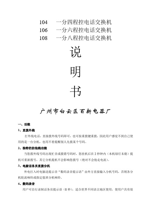
104 一分四程控电话交换机106 一分六程控电话交换机108 一分八程控电话交换机说明书广州市白云区百新电器厂一、功能1、直拨外线打外线电话,直接拨外线号码即可,也可按重拨键重拨,因此用户感觉不到自己使用的是一台分机,也用不着提醒别人先拨某个号码。
2、独特的防抢线功能当您拨外线号码出现忙音或拨错号码时,您挂机后在2秒钟内(本机绿灯未熄)提机可重新拨号,其它分机提机不会影响您拨号(绝对不会抢走电流)。
3、电脑话务员直拨分机外电打入时电脑送提示音“数码录音提示语”由外方直接输入分机号码,否则各分机轮流响铃或指定值班分机响铃。
4、数码录音用户可自行录制话务员提示语(8秒),适合世界不同语言地区使用,使用户具有很大的灵活性。
5、监听录音效果用户录音后,可自行监听录音效果。
6、人工值班如选用人工值班方式,外电打入时,各分机轮流响铃或指定值班分机响铃。
7、多次转接,自动纠错,转接保持外面电话打入,A分机接听后可以转B分机,B分机接听后转C分机,转接次数不限,转接过程中输错号码不要紧,只需重新输入正确号码,转接后主转分机听到等待音即可挂机,而不用等被转分有无摘机,线路会自动保持而不中断(外线听等待音。
)错误修正:若转到错误分机,可人工修正,重新拨正确分机号码即可(下面全部操作同样适用)8、三方通话某分机应答外线后,可呼叫另一分机同时与外线三方通话,通话过程中也可切断其中一分机。
转为一分机与外线通话。
9、无应答回叫外电打入,A分机接听后转B分机,B分机响铃6次无人接听,则各分机自动轮流振铃(免打扰分机不响铃),确保通话不中断。
10、内部通话内部分机可以相互呼叫和通话,不经过电信局,所以不用收费。
11、内部传真内部可接多台传真机,不经电信局可互发传真,提高工作效率。
12、抢线功能当两台分机正在内部通话时,其中一台分机需打外线,则可拨“*”再拨本分机号码(1—8),听到外线拨号音即可拨打外线,另一分机自动挂断。
13、外线呼入催挂如果内部通话时有外线打入,可以听到“嘟…嘟…嘟”三声催挂音,此时任一分机挂机,另一分机即可与外线通话。
工作文档SPPA-T3000用户手册(组态手册3)
sSPPA-T3000,用户手册用户组态手册(共4册,第3分册)目,录1,,模板编辑器.................... 错误!未指定书签。
1.1,,启动模板编辑器 ...... 错误!未指定书签。
1.1.1,,退出模板编辑器.. 错误!未指定书签。
1.2,,常规布置................. 错误!未指定书签。
1.2.1,,工具栏.................. 错误!未指定书签。
1.2.1.1,,标准............... 错误!未指定书签。
1.2.1.2,,链接............... 错误!未指定书签。
1.2.1.3,,排列............... 错误!未指定书签。
1.2.1.4,,图形布局....... 错误!未指定书签。
1.2.1.5,,交互式绘图工具错误!未指定书签。
1.2.2,,模板的上下文菜单错误!未指定书签。
1.2.3,,单一、持久模式.. 错误!未指定书签。
1.2.4,,选项...................... 错误!未指定书签。
1.2.5,,窗口...................... 错误!未指定书签。
1.2.6,,保存视图.............. 错误!未指定书签。
1.3,,模板功能................. 错误!未指定书签。
1.3.1,,保存模板.............. 错误!未指定书签。
1.3.2,,以新的名字保存模板错误!未指定书签。
1.3.3,,打开库.................. 错误!未指定书签。
1.3.4,,编辑模板.............. 错误!未指定书签。
1.3.5,,创建新的模板...... 错误!未指定书签。
1.3.6,,删除模板.............. 错误!未指定书签。
1.3.7,,删除模板库节点.. 错误!未指定书签。
1.3.8,,将模板移动到另一个库节点错误!未指定书签。
ABBACS用户手册
D r i v e I T低压交流传动用户手册高性能矢量控制变频器ACS550-01 变频器(0.75160 kW)ACS550 变频器相关手册通用手册ACS550-01/U1 用户手册(0.75…160 kW)•安全指南•安装•起动•内置现场总线•现场总线适配器•诊断•维护•技术数据法兰安装指导组件, IP21 / UL type 1 外形尺寸编号FMK-A-R1 R1FMK-A-R2 R2FMK-A-R3 R3FMK-A-R4 R41R5 ACS800-AC8-FLNGMT-R6 1 R6 PNTG01U-EN 组件, IP54 / UL type 12 外形尺寸编号FMK-B-R1 R1FMK-B-R2 R2FMK-B-R3 R3FMK-B-R4 R4可选件手册( 手册和可选件一起发货 )MFDT-01 FlashDrop 用户手册英文 )OHDI-01 115/230 V 数字输入模块用户手册3AUA0000003101 ( 英文 )OREL-01 继电器输出扩展模块用户手册3AUA0000001935 ( 英文 )OTAC-01 脉冲编码器接口模块用户手册3AUA0000001938 ( 英文 )RCAN-01 CANopen 总线适配器用户手册英文 )RCCL-01 CC-Link 总线适配器用户手册3AUA0000061340 ( 英文 )RCNA-01 ControlNet 总线适配器用户手册英文 )RDNA-01 DeviceNet 总线适配器用户手册英文 )RECA-01 EtherCAT 总线适配器用户手册3AUA0000043520 ( 英文 )REPL-01 Ethernet POWERLINK 总线适配器用户手册3AUA0000052289 ( 英文 )ACS550 User’s Manual RETA-01 Ethernet 总线适配器用户手册英文 )RETA-02 Ethernet 总线适配器用户手册英文 )RLON-01 LonWorks 总线适配器用户手册英文 )RPBA-01 PROFIBUS-DP 总线适配器用户手册英文 )R ET A-01 Ethernet 总线适配器用户手册3AUA0000042896 ( 英文 )技术目录•安全•安装•起动•故障诊断•技术数据维护手册ACS50, ACS55, ACS150, ACS310, ACS320,ACS350, ACS550, ACH550 电解电容重整指导英文 )CANopen 为 CAN 公司所持有的注册商标。
网络存储快速操作文档
Topstor TT-5300快速操作手册一、磁盘阵列管理 (2)二、快速安装 (2)三、系统设置 (2)1、IP地址设定(方便管理员远程管理) (3)2、语言设定 (3)3、登陆设置 (4)4、更改系统管理密码 (4)5、系统日期设定 (4)6、邮件设置 (5)7、SNMP设置 (5)8、Messenger设置 (5)9、系统事件服务器设定 (6)10、系统日志查看 (6)四、iSCSI设置 (6)1、NIC设置 (7)2、设置NIC IP地址 (7)3、设置网卡的绑定 (7)4、设置网卡的MTU值 (7)5、Session 查看当前的会话 (8)五、卷设置 (8)1、物理磁盘 (8)2、创建卷组 (9)3、创建用户数据卷 (10)4、高速缓存卷 (11)六、监控管理 (11)七、系统维护 (12)一、磁盘阵列管理通过WEB界面进行管理http://192.168.0.1(可在LCD控制面板查看)Login name: adminDefault password: 1234二、快速安装快速安装下可以直接设置RAID 选择RAID级别单击下一步设置卷的大小选择LUN号单击下一步确定即可。
三、系统设置1、IP地址设定(方便管理员远程管理)2、语言设定4、更改系统管理密码5、系统日期设定7、SNMP设置8、Messenger设置9、系统事件服务器设定10、系统日志查看四、iSCSI设置1、NIC设置可设置NIC 的IP地址、子网掩码、查看MAC地址、多网卡绑定等2、设置NIC IP地址3、设置网卡的绑定4、设置网卡的MTU值Node5、Session 查看当前的会话五、卷设置1、物理磁盘查看磁盘槽位、容量大小、当前的状态、磁盘速度等2、创建卷组创建RAID 组单击创建设置名称选择RAID的级别选择物理磁盘。
确定。
3、创建用户数据卷4、高速缓存卷创建提供用户访问的逻辑单元六、监控管理访问控制、对硬件的监控、磁盘扫描的分析报告、不简短电源管理SES配置硬件监视器监视硬件的信息。
通信管理机用户手册
目录1.概述PowerSA-C104t通信管理机是为满足工业自动化需求所设计,具有体积小、低耗电、无风扇、宽温运行、高抗干扰性等特性,是一款真正的工业级产品。
该设备广泛应用于电力系统、石油、化工、水处理、工厂自动化、交通等工业控制领域。
PowerSA-C104t通信管理机应用于采集智能设备分散、监视采集数据量少的小型规模的监控系统中,可实现实时数据的综合处理功能、通信管理、数据网关、数据转发、规约转换、前置处理等各种角色等功能,可以作为功能子站、间隔层,通过层层级联实现数据的分类别、分方向传送。
主要特点采用嵌入式实时操作系统Linux为平台;采用高性能高可靠性嵌入式低功耗硬件平台,使产品的稳定性和宽温运行得到可靠保证;高品质的工业级元件,高水准的电气设计,高密度集成的电路结构,使装置拥有优异的电气隔离和电磁屏蔽表现,极大提高了装置的抗干扰性能与可靠性保障;与智能采集装置、继电保护具有相同等级的EMC;内置丰富规约库IEC 870-5-101、102、103、104, CDT、MODBUS SPABUS SC1801 COURIER DL645 及国内外各主要电力厂家各设备通讯规约,根据现场需求进行特殊规约的开发;单个串口通过RS485总线方式连接多台IED设备;装置的工作电源输入电压为交直流85~264V,可广泛适用于各种供电环境;宽温运行:运行温度-25℃~70℃导轨安装方式,造型美观,组屏方便;主要功能1)PowerSA-C104t通信处理机的可满足不同的应用功能;可以为不同的后台SCADA系统、电力保护装置、各种智能设备、不同的管理系统等提供包含以太网、标准RS232、标准RS485等不同通信接口的综合数据通信处理功能,2)具有USB接口,可直接连接打印机,实时打印相关报警信息等,可作为实时报警打印服务处理中心,弥补了国外保护不具备打印的功能。
(该功能仅PowerSA-C104tp具有)3)实现通信管理、数据网关、数据转发、规约转换、前置处理等各种角色;可以按需组合成分布网络、分层级联灵活通信处理方案。
- 1、下载文档前请自行甄别文档内容的完整性,平台不提供额外的编辑、内容补充、找答案等附加服务。
- 2、"仅部分预览"的文档,不可在线预览部分如存在完整性等问题,可反馈申请退款(可完整预览的文档不适用该条件!)。
- 3、如文档侵犯您的权益,请联系客服反馈,我们会尽快为您处理(人工客服工作时间:9:00-18:30)。
目录1.概述11.1主要特点21.2 主要功能22. 技术指标32.1容量指标32.2性能指标32.3抗干扰性指标42.4电源42.5环境43. 装置说明43.1装置的前后面板44. 镜像文件下载54.1相关命令格式说明54.2系统文件下载104.3应用文件下载124通信管理机的组态145.1. TBE软件配置准备(本手册使用的配置软件是TBE V2)155.2. PowerSA-C104T通信管理机的配置166 常见故障处理197 装置安装208装置接口及端子定义208.1 电源及接地端子定义208.2 通信接口端子定义208.2.1 以太网口端子定义208.2.2 串口端子定义218.3 通讯管理机施工时注意事项21附录.水晶头(RJ45)接线方法221.概述PowerSA-C104t通信管理机是为满足工业自动化需求所设计,具有体积小、低耗电、无风扇、宽温运行、高抗干扰性等特性,是一款真正的工业级产品。
该设备广泛应用于电力系统、石油、化工、水处理、工厂自动化、交通等工业控制领域。
PowerSA-C104t通信管理机应用于采集智能设备分散、监视采集数据量少的小型规模的监控系统中,可实现实时数据的综合处理功能、通信管理、数据网关、数据转发、规约转换、前置处理等各种角色等功能,可以作为功能子站、间隔层,通过层层级联实现数据的分类别、分方向传送。
1.1主要特点●采用嵌入式实时操作系统Linux为平台;●采用高性能高可靠性嵌入式低功耗硬件平台,使产品的稳定性和宽温运行得到可靠保证;●高品质的工业级元件,高水准的电气设计,高密度集成的电路结构,使装置拥有优异的电气隔离和电磁屏蔽表现,极大提高了装置的抗干扰性能与可靠性保障;●与智能采集装置、继电保护具有相同等级的EMC;●内置丰富规约库IEC 870-5-101、102、103、104,DNP3.0 CDT、MODBUS SPABUS SC1801 COURIER DL645及国内外各主要电力厂家各设备通讯规约,根据现场需求进行特殊规约的开发;●单个串口通过RS485总线方式连接多台IED设备;●装置的工作电源输入电压为交直流85~264V,可广泛适用于各种供电环境;●宽温运行:运行温度-25℃~70℃●导轨安装方式,造型美观,组屏方便;1.2 主要功能1)PowerSA-C104t通信处理机的可满足不同的应用功能;可以为不同的后台SCADA系统、电力保护装置、各种智能设备、不同的管理系统等提供包含以太网、标准RS232、标准RS485等不同通信接口的综合数据通信处理功能,2)具有USB接口,可直接连接打印机,实时打印相关报警信息等,可作为实时报警打印服务处理中心,弥补了国外保护不具备打印的功能。
(该功能仅PowerSA-C104tp具有)3)实现通信管理、数据网关、数据转发、规约转换、前置处理等各种角色;可以按需组合成分布网络、分层级联灵活通信处理方案。
4)主站通信功能:装置内部集成了多个主站规约(可选择);能够实现最多与4个主站通信功能。
5)智能装置通信功能:装置可通过不同的规约实现与不同的各种保护装置、智能设备进行通信。
6)实时数据库功能:装置内部自用的模拟量输入、数字量输入、累加量输入、控制输出、设点输出、通用数据块输入、通用数据块输出。
7)内置丰富规约库:装置内部IEC 60870-5-101/102/103/104、DNP3.0 CDT、MODBUS SPABUS SC1801COURIER 等,可根据现场需求进行特殊规约的开发;8)内部通信功能:装置可实现与PowerSA-C系列测控系统及其他PowerSA-C系列通信管理机之间实现通信功能;采用PowerSA-C系列分布平台提供的消息机制交互通信。
9)计算功能:实现模拟量和数字量的各种算术、逻辑、条件和函数运算,可实现各种闭锁逻辑,特别适用于控制和设点输出的闭锁。
10)具有灵活的在线、离线调试手段,可靠的程序升级、下载参数及数据查询、报文监视、原始值、工程值等功能;11)模拟量仿真:仿真物理AI 输入和物理AO 输出,模拟测试和调试数据。
12)数字量仿真:仿真物理DI 输入和物理DO 输出,模拟测试和调试数据。
2.技术指标2.1容量指标●以太网接口:1个10/100M以太网口;●串行通信接口数: 4个RS232/RS485/RS422;●报警节点:1个报警干节点;●通信主站规约数: <=4/每台;●每一路均可为独立的全双工串行通道;●数据传输速率,300bps - 38.4kbps,软件可编程、可配置;●数据传输方式,全双工或半双工;2.2性能指标●可接智能设备数:小于3s时 20个以内取决于规约,最大可挂40台;●数据处理相应时间≤0.3秒●数据容量(单台):模拟量: <= 2000;数字量: <= 5000;控制量: <= 200;设点量: <= 200;累加量: <= 200 计算量: <= 100;注:保护定值单独处理不包括在数据库里●MTBF——大于50,000小时2.3抗干扰性指标●静电放电 GB/T17626-4-23级●快速瞬变GB/T17626-4-43级●冲击涌流 GB/T17626-4-53级●串口光电隔离 2500V光电隔离绝缘●绝缘电源输入对机壳 2500 VAC通信信号对机壳 500 V2.4电源●工作电源:AC80-264V或DC110-220V,工作频率:45-55HZ2.5环境●工作温度:-25℃- +70℃,相对湿度5-95%,无凝结3.装置说明PowerSA-C104t嵌入式装置是一种紧凑结构的通用通信装置,具有1个以太网接口、4个RS232/485/422串口,具有高抗干扰性能;外观设计美观。
内部采用高可靠性的单板式硬件模块;系统安装、维护方便。
3.1装置的前后面板4.镜像文件下载4.1相关命令格式说明1.插上网线,插上串口线,打开超级终端,需注意的是波特率要设为115200bps,数据流控制为:无复位键背板1个以太网口4个RS232/485/422口USB打印端口电源端子接地桩报警输出电源指示灯网络指示灯前板2.给通信管理机通电,注意超级终端出现以下界面时,按下“Esc”键,进入下图所示:3.查看IP地址,波特率等参数,用“SET”命令,如下图所示:如不太熟习可以用“SET —?”命令,如下图所示:MAC设置主机MAC地址﹝出厂时如果是同一个系统的设备MAC地址设置都要不相同﹞,用“SET”命令,命令格式为“set —mac0 00 00 00 00 00 02”,需要注意的是只能修改后面的3位,即“set —mac0 00 00 00 ××××××”如下图所示:IP Address设置主机IP地址,此地址是PowerSA-C104t用来下载linux.zip和romfs.img的虚拟地址,与PowerSA-C104t的实际地址意义不同,但IP可以相同,和计算机的IP在同一网段即可。
用“SET”命令,以192.168.8.118为例,命令格式为“set -ip0 192.168.8.118”,如下图所示:DHCP Client设置DHCP Client,用“SET”命令,命令格式为“set —dhcp 0”,注意一定要都设为“Disabled”方式,如下图所示:4.设置装置IP地址,此地址为设备实际地址,在设置之前,可以先看一下帮助,用“F —?”命令,如下图所示:设置装置IP地址等,用“F”命令,以192.168.8.253为例,命令格式为“f-id 0xfd-clock 1 -ip0192.168.8.253 -netmask 255.255.255.0”,如下图所示:查看装置IP地址,用“d”命令,命令格式为“d 0x7f500000”,如下图所示:装置MAC地址装置IP地址装置IP掩码4.2系统文件下载AM7的镜像分2个,分别是系统镜像和应用镜像,下载时需先下载系统镜像,再下载应用镜像。
下载之前,可以先看一下帮助,用“FT —?”命令,如下图所示:下载系统镜像,用“FT”命令,命令格式为“ft7 linux.zip 0x7f020000 0x8000 –acxz” ,如下图所示:下载的时候需打开FTP,需要进入DOS提示符下输入命令来进行操作,命令格式为“tftp -i 162.168.8.79 put linux.zip”如下图所示:﹝162.168.8.79)是前面所说的装置的虚拟IP地址﹞需注意:“linux.zip”文件放的位置就是下载的盘符路径。
如上图所示:“linux.zip”文件放在D:\下,下载时需要先把超级终端里的命令写完,不要敲“Enter”键运行,写好DOS下的命令后,先在超级终端里面敲“Enetr”键运行,再在DOS下面敲“Enter”键运行。
如果要重新下载,也可以先手动清空ROM里面的内容,命令为“DEL”,命令格式为“del 7”,如下(此命令重新下载时可以不单独操作,会自动在下载时提示执行)图所示:4.3应用文件下载1.下载之前,可以先看一下帮助,用“FT —?”命令,如下图所示:2. 下载之前,必须先看一下系统镜像占用的地址区间,以确定应用镜像的起始地址,命令为“LS”,如下图所示:﹝即0x7F020000+0x0006cc78=0x7F08cc78 所得到的地址不能大于应用镜像的起始地址﹞3.下载应用镜像,用“FT”命令,命令格式为“ft 6 romfs.img 0x7f0c00000x7f0c0000 –a”,如下图所示:﹝应用镜像的起始地址0x7f0C0000大于系统镜像占用末地址0x7F0A5F98﹞4.下载的时候需打开FTP,打开FTP和以前的方法不同,需要进入DOS提示符下输入命令来进行操作,命令格式为“tftp -i 162.168.8.79 put romfs.img”如下图所示:需注意:“romfs.img”文件放的位置就是下载的盘符路径。
同linux.zip文件一样。
下载时需要先把超级终端里的命令写完,不要敲“Enter”键运行,写好DOS下的命令后,先在超级终端里面敲“Enetr”键运行,再在DOS下面敲“Enter”键运行。
5.如果要重新下载,也可以手动先清空ROM里面的内容,命令为“DEL”,命令格式为“del 6”,(此命令重新下载时可以不单独操作,会自动在下载时提示执行)如下图所示:全部下载完毕后可以使用ls 命令查看。
如上图6.系统重启输入boot后回车,系统重启。
至此,镜像文件下载完成。
4通信管理机的组态TBE是PowerSA系列产品的专业配置维护工具,是一个功能强大的组态软件,以工程项目为单位,管理项目内的多个装置和装置的各种应用模块,为用户及工程技术人员提供了高效且简单易学的项目工程化手段。