Pantec调试手册
赛普6000大屏处理器使用说明书分析

SMS6000系列多图像拼接墙处理器系统用户手册大屏幕拼接处理器在使用本系统前,请详细阅读本说明书.并请保管好该手册!安全操作指南为确保设备可靠使用及人员的安全,在安装、使用和维护时,请遵守以下事项:系统接地系统必须有完善的接地。
否则,不仅造成信号干扰、不稳定或机械损坏,而且还可能因漏电引起人身事故。
RGB、VGA、AV切换矩阵的最终接地点应连接至真地,其接地电阻应小于1Ω。
禁止改变原设计禁止对本产品的机械和电器设计更改或增添任何部件。
否则,生产厂家对由此所带来的危害性结果不负责任。
请勿使用两芯插头,确保设备的输入电源为220V 50Hz的交流电。
机器内有交流220V高压部件,请勿擅自打开机壳,以免发生触电危险。
不要将系统设备置于过冷或过热的地方。
设备电源在工作时会发热,因此要保持工作环境的良好通风,以免温度过高而损坏机器。
阴雨潮湿天气或长时间不使用时,应关闭设备电源总闸。
在下列操作之前一定要将设备的交流电源线从交流供电电源插座拔下:A.取下或重装设备的任何部件。
B.断开或重接设备的任何电器插头或其它连接。
非专业人士未经许可,请不要试图拆开设备机箱,不要私自维修,以免发生意外事故或加重设备的损坏程度。
不要将任何化学品或液体洒在设备上或其附近。
目目录第一章系统简介 (4)第二章技术参数 (9)第三章控制管理软件介绍和使用 (10)第四章大屏控制器控制指令集 (21)第五章安装说明 (23)第六章常见故障分析及解决 (29)第一章系统简介一大屏幕拼接处理器SMS6000系列多屏拼接器是一款纯硬件的专业化的图像处理设备,能够将多个动态画面显示在多个屏幕上面,实现多窗口拼接的功能。
专为高质量显示多个画面的场合设计,为指挥中心、视频会议、多媒体多功能厅等场所的应用提供了一套理想的图像处理解决方案。
图1 系统图SMS6000系列多屏幕拼接控制器采用大容量高速FPGA 阵列和高速数字总线交换技术架构,结合全数字硬件设计理念,实现无操作系统视频图像处理工作站。
PANTEC控制系统介绍

•Probe Systems:Touch Trigger Probes: TP2, TP6,TP20, OTP6, TP7M, TP200Scanning Probes: SP25, SP80, SP600 Optical Probes: WENZEL PHOENIXWENZEL CMM with WPC: a perfect system from operator to probe systems METROMEC Software AGRheinfelsstraße 1CH-7007 ChurTelefon: +41 (0) 81/257 07 00Telefax: +41 (0) 81/257 07 01Mail: metromec@metromec.chwww.metromec.chWENZEL America Ltd.28287 Beck Road, Unit D-1USA-Wixom, MI 48393Telefon: +1/248/596 11 93Telefax: +1/248/596 11 94Mail: info@WENZEL PRÄZISION GmbHWenzel-Präzision-StraßeD-97859 WiesthalTelefon: +49 (0) 6020/201-0Telefax: +49 (0) 6020/201-19 99Mail: info@WENZEL GearTec GmbHIm Mittelfeld 1D-76135 KarlsruheTelefon: +49 (0) 721/170 87-0Telefax: +49 (0) 721/170 87-200Mail: info@wenzel-geartec.dewww.wenzel-geartec.deDIN EN ISO 9001, VDA 6.4DIN EN 14001 With branches in Switzerland,France, England, the Netherlands,USA and Brazil, Sales and Servicepartners take care of WENZELtypical WENZEL…400 precision measuring machinesevery year – and growing.Innovative middle-sizeAward for innovativeFunctional Overview W P C 2030/3W P C 2030/4W P C 2030/4 H PE t h e r n e tS P 25/S P 600S P 80/S P 2P H SH T 400H T 400R CS p a r e b a t t e r yB a t t e r y c h a r g e rBasic units 1Options 2Control 23 CMM-axes Standard 6A/60V 3 CMM-axes High Power 8A/120V 3 CMM-axes with 4th axis for dual-drive 3 CMM-axes with 4th axis for milling 3 CMM-axes with 4th axis for rotary table Integration of all Renishaw Touch Trigger Probes Hand terminal, wired Hand terminal, wirelessHand terminal, wireless (2 and/or 3 shift operation)SW/HW for integration Renishaw PHS-1SW/HW for Scanning Probe SP25SW/HW for Scanning Probe SP600SW/HW for Scanning Probe SP80SW/HW for Scanning Probe SP2-1SW/HW for Scanning Probe OTM3Optical sensor WENZEL PHOENIX Number of points >50 points/s1 See Technical Data for details of basic unit2 Controls and options can be used in each of the three basic unitsCommon• 19“ Rack, height 3HE, depth 470mm • weight 19kg• direct connection to 230V (repluggable to 110 volt), 50/60Hz, single-phase • connected load 1300Watt • 2 x 10 A fuse in port • integrated line fi lter• complies with EN50082, EN50081 regulations • temperature range – operation: 10°C to 45°C • relative air humidity: 10% to 95% non-condensing Performance• scanning times of 0.866ms (up to 4 spindles)• max. positioning speed with 1µm resolution up to 5m/sec • Lookahead • acceleration profi le S-profi le • …round-corner“-interpolationMotors• 4 DC-servo motors Irms 6A/60V with Tachometer Feedback systems • I ncremental RS422• 1/T Sub-count Interpolation• counter frequency to max. 10MHz • connection facilities for incremental transducer (5V-TTL)Probe Systems • Touch Trigger Probes:TP2, TP6, TP20, OTP6, TP7M, TP200• Scanning Probes : SP25, SP80, SP600• Optical Probes : WENZEL PHOENIXSafety devices/diagnosis/setup • integrated watchdog• diverse LED‘s for display of operating state of all important components on the front panelInterfaces• connection for joystick console for manual traversing of 4 spindles (analog inputs 0-5V, 8bit)• limiting-switch inputs • RS232/RS422 interface for communication (9600 to 115200 Baud)• optional Ethernet (TCP/IP)Safety circuit• emergency OFF circuit with safety relay as per EN 60204• one 24V, potential-free break contact • one 24V, potential-free make contact for servo-power ON-keyinput/outputs …Optional“ plugs• 12 inputs 24V/PNP• 4 outputs 1A/24V (sinking)…Emergency“ plugs• 3 outputs 100mA/24V (sourcing)• 2 inputs 24V …Terminal“ plugs• 4 analog inputs 0-5V, 8-Bit resolution (e.g. joystick connection)• 8 inputs 24V/PNP …I/O“ plugs• 8 inputs 24V/PNP• 8 outputs 24V/0,5 A (sourcing)…Opto Interface“ plugs• additional key inputs (e.g.: optical keys)Hardware capture• A fast incident counter with which the corresponding counter count can be stored on an external signal for all spindles (hardware latch)Technical Data WPC 2030/x incl. OptionsWPC 2030: Universal CMM Controller Platform The WPC 2030 is the latest generation of the popular WPC series. WPC users value the continuity of this series. Permanent soft and hardware upgrades compatible with lower versions, together with continual integration of new probe systems, provide a unique and safe investment. The current range of supported probe systems ranges from the complete Renishaw assortment to the new WENZEL X optical sensor. The WPC has been the only controller on the market for years to support the Renishaw With the new HT400 hand-operated terminal series – and especially WENZEL Wireless Technology – WENZEL has become a pioneer in the operator philosophy of CMM technology. The hand-held terminals permit higher productivity with their unique ease-of-use.The open WPC platform is also ideally suited for Retrofi t.Hand-held unit HT400The ergonomically designed HT400 in cable version, as well as the HT400RC with radio connection, provide a multi-functional hand-operated unit for comprehensive CMM control.Metrosoft CMThe WPC and the Metrosoft CM software are perfectly coordinated. The measurement software excels – supported by self-explanatory graphics – with its logical and simple guidance for the user. nterfaces are also available for other established measurement software packages. A fast Ethernet interface has been developed for the WPC for swift technical measurement of complex parts, as e.g. gear wheels. This guarantees a very high rate of data to measurement software via a standardized interface.WPC 2030The WPC 2030 combines the latest CNC technology with absolute dependability. Thanks to the high degree of integration, the number of components has been greatly reduced, guaranteeing the highest degree of operational safety.。
纳博特20.06控制系统操作手册说明书

2020控制系统操作手册20.06纳博特目录第2章安全注意事项 (15)注意事项 (15)第3章产品组装 (16)3.1示教盒安装 (16)3.2控制柜安装 (16)3.2.1线缆要求 (17)3.2.2布线要求 (18)3.2.3接地要求 (18)3.2.4接线注意事项 (19)第4章新机器人配置步骤 (20)第5章机器人的坐标系与轴操作 (26)5.1控制组与坐标系 (26)5.1.1坐标系 (26)坐标系与轴操作 (27)5.1.2关节坐标系 (27)5.1.3直角坐标系 (28)5.1.4工具坐标系 (29)5.1.5用户坐标系 (30)5.2外部轴 (33)第6章示教器按键与界面简介 (34)6.1T20示教器物理按键 (34)6.2T30示教器物理按键 (35)6.3操作系统简介 (37)6.3.1基本说明 (37)6.3.2状态介绍 (37)6.4界面介绍 (38)6.4.1主页 (38)6.4.2用户 (39)6.4.3设置 (41)6.4.4用户坐标标定 (43)6.4.5系统设置 (44)6.4.6远程程序设置 (48)6.4.11Modbus设置 (69)6.4.12后台任务 (71)6.4.13网络设置 (72)6.4.14数据上传 (73)6.4.15程序自启动 (73)6.4.16操作参数 (74)6.4.17工艺 (75)6.4.18变量 (103)6.4.19状态 (105)6.4.20工程 (107)6.4.21程序 (108)6.4.22日志 (109)6.4.23监控 (110)第7章机器人示教与运行 (111)7.1机器人准备 (111)7.1.1开机与安全确认 (111)7.1.2示教器准备 (111)7.2点动操作 (111)7.2.1示教速度调节 (112)7.2.2坐标系说明与切换 (112)7.2.3点动操作 (113)7.3程序编写 (113)7.3.1程序新建/打开/删除/重命名/复制 (113)7.3.2指令操作 (118)7.3.3指令说明(指令规范) (122)7.4程序运行 (142)7.4.1示教模式 (143)7.4.2运行模式 (143)7.4.3远程模式 (143)7.4.4从当前行运行 (145)7.5.4远程IO速度修改方式 (147)第8章工具手与用户坐标 (149)8.1工具手标定 (149)8.1.1工具坐标系 (149)8.1.2TCP:TOOL CENTER POINT,即工具中心点 (149)8.1.3工具坐标系特点 (150)8.1.4工具手参数设置 (151)8.1.57点标定 (152)8.1.612/15点标定 (156)8.1.720点标定 (161)8.1.82点标定 (162)8.2用户坐标系 (163)8.2.1用户坐标系作用 (164)8.2.2用户坐标参数设置 (165)8.2.3用户坐标系标定 (165)第9章数值变量 (167)9.1变量的名称 (167)9.2全局数值变量 (167)9.3全局数值变量使用 (169)9.3.1定义全局数值变量 (169)9.3.2通过计算指令为全局数值变量赋值 (169)9.3.3直接变量赋值 (171)9.3.4使用全局数值变量来计数 (172)9.4局部数值变量 (172)9.5局部变量使用 (173)9.5.1定义局部数值变量 (173)9.5.2使用计算指令为局部变量赋值 (174)9.5.3直接为变量赋值 (174)第10章位置变量 (175)10.1全局位置变量 (175)10.3.4READPOS 指令 (179)10.3.5USERFRAME_SET 指令 (180)10.3.6TOOLFRAME_SET 指令 (180)10.3.7COPYPOS 指令 (180)10.44轴SCARA机器人左右手 (180)10.4.1全局变量设置左右手 (181)第11章条件判断类指令的使用 (183)11.1指令说明 (183)11.1.1CALL (183)11.1.2IF (183)11.1.3ELSE (184)11.1.4ELSEIF (185)11.1.5WHILE (187)11.1.6WAIT (188)11.1.7LABEL (189)11.1.8JUMP (190)11.1.9UNTIL (191)11.1.10CRAFTLINE (192)11.1.11CMDNOTE (192)11.1.12POS_REACHABLE (192)11.1.13CLKSTART (193)11.1.14CLKSTOP (193)11.1.15CLKRESET (193)第12章后台任务 (194)12.1限制 (194)12.2注:运行模式按暂停按钮、远程模式IO暂停只暂停主程序,不暂停后台任务 (194)12.3后台任务编程 (195)12.3.1注意 (195)12.4主程序编程 (195)12.4.1PTHREAD_START(开启线程) (195)12.4.4CONTINUERUN(继续线程) (197)12.4.5STOPRUN (停止运行) (197)12.4.6RESTARTRUN(重新运行) (198)第13章IO、Modbus与远程程序 (199)13.1IO (199)13.1.1输入输出指令 (199)13.1.2I/O功能选择设置 (200)13.1.3IO状态提示设置 (201)13.1.4IO安全设置 (202)13.1.5IO复位 (202)13.1.6IO配置 (203)13.1.7使能IO (204)13.1.8报警消息 (205)13.1.9端口名称 (205)13.1.10远程模式IO预约简要说明 (206)13.2远程程序设置 (208)13.3复位点设置 (208)13.4远程功能的使用(IO) (209)13.4.1远程功能概述 (209)13.4.2远程功能使用步骤 (209)13.4.3编写程序 (209)13.4.4设置远程程序 (209)13.4.5设置IO (210)13.4.6切换到远程模式 (210)13.4.7预约排序 (210)13.4.8运行 (211)13.5Modbus修改地址码 (211)13.6Modbus的使用 (214)13.6.1ModBus功能概述 (214)13.6.2Modbus触摸屏使用流程 (214)第14章多机模式与双机协作 (218)14.1设置机器人 (218)14.2切换机器人 (219)第15章视觉工艺 (222)15.1视觉参数设置 (222)15.2视觉范围设置 (224)15.3 (225)15.4视觉位置参数 (225)15.5位置调试 (226)15.6视觉运作方式 (226)15.7视觉指令 (226)15.7.1VISION_RUN (226)15.7.2VISION_TRG (227)15.7.3VISION_POSNUM (227)15.7.4VISION_POS (227)15.7.5VISION_CLEAR (227)15.7.6VISION_END (227)15.8使用示例 (228)15.8.1抓取应用 (228)第16章传送带跟踪 (229)16.1参数设置 (229)16.1.1基本信息 (229)16.1.2识别参数 (230)16.1.3传送带标定 (230)16.1.4传感器标定 (233)16.1.5位置设置 (235)16.2编写程序 (236)16.2.1CONVEYOR_ON指令 (236)16.2.2CONVEYOR_OFF指令 (237)16.2.3CONVEYOR_CHECKPOS指令 (237)16.2.4CONVEYOR_CHECKEND指令 (237)16.3示例 (237)16.3.1使用传感器、MOVJ走轨迹 (237)16.3.2使用传感器、外部发点功能走轨迹 (238)16.3.3视觉传送带跟踪 (238)第17章外部传输点 (240)17.2通讯方式 (241)17.2.1点位存放的数据 (241)17.2.2示例 (242)17.2.3指令 (242)第18章外部通讯 (243)18.1TCP协议 (243)18.1.1参数设置 (243)18.1.2指令 (243)18.1.3READCOMM (244)18.1.4OPENMSG (245)18.1.5CLOSEMSG (245)18.1.6PRINT (245)18.1.7MSG_CONN_ST (245)第19章数据上传 (246)19.1基本设置 (246)19.2数据格式 (246)19.2.1生成csv文件示例 (247)第20章机器人日志 (249)20.1示教器日志查看 (249)日志说明 (249)操作日志:此类型日志保存用户的基本操作,例如新建程序、重命名程序插入指令等。
压力开关调节方法

数控机气路压力开关调节方法目前,我公司共使用四种型号的压力保护开关,分别是SMC的IS1000机械压力开关、GP46机械压力表带压力开关、ISE30型数显压力表压力开关和CKD的PPX型数显压力表压力开关。
一、各种压力开关的设定方法1、IS1000机械压力开关出线的一侧有一个小的旋钮,使用小一字螺丝刀通过调节此旋钮即可改变开关动作的压力值。
在压力开关一侧有一个红色的指示器,可以指示当前的压力设定值。
2、GP46压力表带压力开关设定动作压力是需要逆时针旋转取下压力表的透明保护罩,在压力表盘的下方有一个小的旋钮,使用小一字螺丝刀调节此旋钮即可调节压力开关的动作压力。
压力表上有一个绿色指针,此指针指示设定的动作压力。
注意在调好动作压力之后将压力表的保护罩再装上去。
说明:由于IS1000和GP46属于机械式压力开关,所以他们的动作压力指示器会存在0.05MPa以下的指示误差,还会存在0.08MPa的动作迟滞。
3、ISE30型数显压力表压力开关共有三个按键和一个显示窗口,三个按键分别为“△”、“SET”、“▽”,通过这三个按键可实现压力开关的设置。
持续按“SET”三秒以上即可进入主程序设置,第一个界面是选择压力单位,一般设置为“bar”,如果需要改变单位,通过“△”或 “▽”来改变。
设置到需要的单位后按“SET”进入下一级显示颜色设置。
显示颜色一般设置为“SOG”(ON时为绿色),如果要改变显示颜色同样是通过△”或 “▽”来改变。
显示颜色设置完成后按“SET”进入动作模式设定,一般设置为“HYS”(迟滞模式),继续按“SET”进入输出状态设定,一般设置为“NO”(常开状态)。
继续按“SET”进入响应时间设定,这里设置气压达到设置压力和输出动作信号之间的延时,单位为毫秒。
继续按“SET”进入自动预置设定,一般设置为“MAN”(手动模式,不能设置为“AUT”)。
再继续按“SET”退出主程序设置。
按一下“SET”会出现“P_1”和一个数字的交替闪烁,此数字即为压力开关的动作压力,按“△”或 “▽”可进入动作压力P值的设置界面,显示区显示压力值,且最后一位闪烁,此时通过“△”或 “▽”可以改变最后一位置,通过“SET”可以在不同数字位之间切换,再通过“△”或 “▽”改变当前闪烁的数字位的值。
圆盘刀库加工中心调试说明
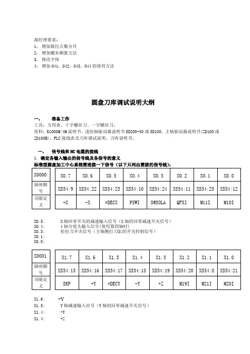
郝经理要求:1,增加限位点数分开2,增加螺补测量方法3,修改字体4,增加G41、G42、G43、G44的使用方法圆盘刀库调试说明大纲一,准备工作工具:万用表、十字螺丝刀、一字螺丝刀,资料:K1000M/4M说明书、进给轴驱动器说明书SD200-30或SD100、主轴驱动器说明书(ZD100或ZD100B)、PLC接线表及刀库调试说明、刀库说明书、一,信号线和NC电缆的接线1,确定各输入输出的信号线及各信号的意义标准型圆盘加工中心系统需连接一下信号(以下只列出需接的信号线):X0.5: X轴回零开关的减速输入信号(X轴的回零减速开关信号)X0.4: 4轴分度头输入信号(使用第四轴时)X0.3: 松拉刀开关信号(主轴侧打刀缸的开关控制信号)X0.1:X0.0:X1.6: +YX1.5: Y轴减速输入信号(Y轴的回零减速开关信号)X1.4: -YX1.4: +ZX1.2: 主轴定位完成输入信号(主轴驱动器定向完成后给系统的完成信号)X1.1: 转台松开输入信号(第四轴使用分度头时放松转台)X1.0: 转台夹紧输入信号(第四轴使用分度头时加紧转台)X2.7: 主轴报警信号输入(检测主轴报警的信号)X2.6: -ZX2.5: Z轴减速输入信号(Z轴回零的减速开关信号)X3.6: 紧刀到位信号(主轴内紧刀到位信号)X3.5: 4轴减速输入信号(第四轴的回零减速信号)X3.3:ESP 急停(附加面板)X3.2: 暂停(附加面板)X3.1: 启动按钮(附加面板)X3.0: 程序开关(使用外部的程序开关)X100.0 数刀信号(刀库上的计数信号)X100.1 倒刀磁开关信号(刀套倒下和水平面平行时的位置检测信号)X100.2 回刀磁开关信号(刀套倒下和水平面垂直时的位置检测信号)X100.3 扣刀确认信号X100.4 原点确认信号X100.5 马达停止信号X100.6 打刀极限开关信号(松刀到位信号)X101.0 零位信号(刀库的零位信号正常最好接通,防止刀库出现乱刀现象时恢复刀库正常状态 )X101.1 手动刀库正转信号(可在外部增加开关单独控制刀库的正转方便在调试时使用)X101.2 手动刀库反转信号(可在外部增加开关单独控制刀库的反转方便在调试时使用)X101.3 刀库确认信号输出信号诊断表Y0.6: 红色报警灯的信号输出Y0.4: 润滑油开(如用系统控制油泵时可用该信号进行控制,如不用系统控制时可不接)Y0.3: 冷却液开输出(控制水泵开关的控制信号)Y0.1: 主轴反转Y0.0: 主轴正转Y1.7: 加工完成黄色灯信号的输出Y1.6: 模拟主轴输出指示Y1.4: 润滑油关脉冲输出Y1.1: 转台放松输出信号Y1.0: 转台夹紧输出信号Y2.7: 松刀输出信号Y2.6: 分度头气动放松输出Y2.3: 主轴定向输出Y2.1: 模拟主轴高档输出Y2.0: 模拟主轴低档输出Y100.0 刀盘正转Y100.1 刀盘反转Y100.2 倒刀(刀套倒下垂直水平面)Y100.3 回刀(刀套回位平行水平面)Y100.4 拉刀(紧刀输出信号)Y100.5 手臂马达动作(机械手动作的控制信号)Y100.6 模式切换输出(使主轴驱动器进入位置控制方式信号)2,NC电缆的连接根据系统侧背面的插头编号和电缆编号连接NC、主轴驱动器、进给轴驱动、主轴电机、进给轴电机之间的电缆。
派特操作手册简易本

目录PAD系统简介 (3)培训主题概述 (4)电脑基本知识 (5)打版放码系统 (7)生产实际流程 (9)纸样操作介绍 (10)排料操作介绍 (24)南京贝特CAD技术有限公司NANJING BETTER CAD TECHNOLOGIES CO., LTD.地址:南京市江宁区文靖路59号E-mail:316387972@PAD系统简介欢迎使用PAD计算机辅助服装设计系统。
PAD公司(PAD System Technologies)是世界最先进的服装CAD/CAM专业技术公司之一,其总部设在加拿大的蒙特利尔,在美国设有分部。
PAD在全球的54个国家和地区共有11,000多家用户。
本系统提供各种工具,用户可以在电脑上直接完成制版、打刀眼、打洞眼、贴边、作缝份、作省、省转移、剪切、拼接等传统的制版方法;并提供三种形象的放码方法,以应不同客户的需要;自动排料及人机交互式排料,灵活方便;独有的三维立体试衣,即时体现设计效果,同时检验版形线条,已减少生产失误。
系统的特点:1、系统操作灵活、方便、快速a、简单易学,操作方便;b、多视窗下编辑及修改;c、样片、设计图、排料图可在同一视窗或多个视窗间任意修改、复制/粘贴,以及多个模块间的复制/粘贴;d、排料图上可直接进行纸样编辑、修改。
2、苹果机和PC机下的WINXP的工作环境通用,操作界面亲切。
3、 PAD(派特)系统是个开放的系统a、能驱动三十多种绘图仪、二十多种数字化仪;b、图形及文本文件或其它著名服装CAD设计软件的数据库文件,如Gerber、Lectra等,都可在PAD(派特)系统环境下运行;4、独有的真三维立体试衣效果5、能适合每个人体需要,进行量身度做6、十四种语言版本可任意的选择、转换7、根据客户规模大小而定做的各种模块,不仅适应个人同时也适合大型企业培训主题概述派特系统的培训是使用户对技术的理解达到一个高的水平。
通过理论和实践的案例,用户将理解并能预估,在视窗上打板、放码及排料的不同步骤。
新代系统调试手册v1.3教学文稿
8轴(含)以下
I/O基址
0X340
(832)
0X320
(800)
JP16(4)
JP15(3)
JP14(2)
JP13(1)
轴卡二片以下Pr01800轴卡超过二片Pr01768
2.Servo_6的第一片轴卡基址为768
(目前一部控制器仅支援一张Servo_6,不可与Servo_4混插)
3.Embedded第一片轴卡基址固定为512
CN2 (公)
Relay 1
X88~X95
Y96~Y110
PIO3_3
CN1 (母)
Relay 2
X120~X159
Y120~Y131
CN2 (公)
Relay 1
X48~X55
Y56~Y70
4
PIO3_1
CN1(母)
Relay2
X00~X39
Y00~Y11
CN2(公)
Hardkey2
X40~X136
PIO4_2
X120~X151
Y120~Y135
PIO4_3
X160~X191
Y160~Y191
PIO4_4
X200~X231
Y200~Y231
组态
位址
接头
I/O板
型态
Input (X)
Output (Y)
6
PIO5_1
XI1
TB16IN
X00~X15
XI2
TB16IN
X16~X31
XI3
TB16IN
G28及G30参考点回归指令会复归到最初原点复归动作之机械原点。
支援背隙补偿、节距补偿及寻原点栅格量检查功能。
Pentair 泵组控制面板安装和维修手册说明书
NOTE! To the installer: Please make sure you provide this manual to the owner of the equip m ent or to the responsible party who maintains the system.MODEL CNC-600-43DW (60 HP, 460V, 3 PH)CNC CONTROL PANELSINSTALLATION AND SERVICE MANUALFor Duplex 460V, 3 Phase.Part # 23833A167 | © 2012 Pentair Pump Group, Inc. | 11/08/1223833A167 11/08/122LOCATION AND MOUNTINGPOWER SUPPLYINDOOR USELocate the control box in a convenient location, preferably close to the pump installation. The box may be secured to a wall or other stable vertical support by use of the four mounting holes located in the mounting feet on the top and bottom of the box.The box should be mounted approximately 5 feet from the floor to the circuit breaker handle. Care should be taken to avoid mounting the control box under sweating pipes, faucets or other damp locations.OUTDOOR USEThe control box may be mounted at the location of the pump and basin or may be mounted in a remote location. The box should be secured to a stablevertical support which in turn should be secured to a concrete basin or footer. The box could also bemounted to the side of the house or other stationary support if available within a reasonable distance.When selecting a location, you should consider the visibility of the alarm light.The box may be secured by the use of four mounting holes located in the mounting feet on the top and bottom of the box. The box should be mounted approximately 5 feet from the ground to the circuit breaker handle.WARNING:Do not attempt to wire this control box unless you have a good working knowledge of electricity and are familiar with state and local codes. If you are in doubt about anything, contact an electrician.Do not attempt to operate this unit on any other voltage or power distribution other than for which it was originally designed (check nameplate). Failure to comply with this will result in the immediate cancellation of all warranties and claims.It is advisable to put the panel on its own circuit using a circuit breaker adequately sized to protect the pump(s). Check state and local codes for the correct wire size and circuit protection to use. The wire should be sized large enough to handle the full load current of the pump(s) you are operating and any voltage drop that might occur due to long service runs.Run power supply lines to the control box and secure (knockouts are not supplied in this box).Select a convenient location on the bottom to enter the box with the power supply. Cut a hole with a chassis punch; caution should be taken not to get metal chips in the components while cutting hole. After the hole is cut, any metal particles must be removed from box. Failure to do so may result in premature component failure.Connect incoming power to the terminal blockslabeled L1, L2, L3, and all necessary ground wires to the ground lug at the bottom of the box. The ground lug should be fastened to a good driven earth ground by one of the methods described in the National Electric Code.CALIFORNIA PROPOSITION 65 WARNING: This product and relatedaccessories contain chemicals known to the State of California to cause cancer, birth defects or other reproductive harm.CONNECTING PUMP(S) AND FLOATS TO CONTROL BOXRun the cords from the pump(s) to the bottom of the control box by means of one of the methods described in your pump or basin installation instructions. A hole must be cut into the controlbox (use the same procedure as that describedfor incoming power supply lines).POWER CORD: Connect red, white and black wires to terminals marked M1, M2 and M3. Fasten green wire to ground lug.CONTROL CORD: Connect the black and white wires (motor heat sensor), and the red and orange wires (seal leak probe) to the appropriate terminal blocks. (See wiring diagram for correct terminal numbers.) Fasten green wire to ground lug.FLOAT CORDS: See basin instructions for the proper depth at which to set the floats. Strip the float cord wires 3⁄8", twist strands together, and connect black and white wires to terminal strip in the control box. (See wiring diagram for proper terminal connections.)OPERATING PUMPS1. Make sure that all wires are inside the control boxand not in a position to be pinched or shortedwhen the door is closed.2. Turn on power to the control box.3. Turn hand-off-auto switches to the HAND position.The pumps should start and the pump run lightsshould come on. (On Duplex panels, this should be done for both pumps.)4. The alarm light should activate when the alarm testswitch is used.5. To put into service, put the hand-off-auto switch inthe AUTO position. (On Duplex panels, this should be done for both pumps.) See basin instructions. 6. If unit does not operate as described, seetroubleshooting chart.NOTE: Addition of electrical components and circuitry to this unit is expressly forbidden unless writtenfactory authorization is obtained. Failure to doso will result in warranty cancellation.ROTATION OF THREE PHASE PUMPSIMPORTANT:Rotation of three phase pumps must be established by one of the two methods described below. CAUTION:Keep hands and feet clear of impeller when checking rotation. Be sure to disconnect power to the control box while handling pumps. Make sure pump is wired and readied for rotation test before the control box is energized.1. Before positioning pump in basin, run wires tocontrol box. Lay the pump unit on its side andsecure so that the starting torque of the motor will not cause the pump to roll. Energize the pump by turning the circuit breaker on and the hand-off-auto to HAND. The rotation should be counterclockwise as observed facing the bottom of the pump.If you do not get the proper rotation, disconnectthe power to the control box and change theposition of any two of the black motor leads inthe terminal blocks.2. Install the pump in the basin and run in some waterso the pump can operate. Energize the pump byturning the circuit breaker on and the hand-off-auto switch to HAND. Let the pump pull the waterdown in the basin, and when the water reachesthe bottom of the pump the rotation of the watercan be observed. The water should rotate in aclockwise direction if the pump rotation is correct.If you do not get the proper rotation, disconnectthe power to the control box and change theposition of any two of the black motor leads inthe terminal blocks.23833A167 11/08/12 323833A167 11/08/124CHECKING PUMP CURRENT DRAWCHECKING PUMP AND FLOAT RESISTANCETO CHECK PUMP OR FLOAT, DISCONNECT INCOMING POWER AND REMOVE WIRES FROM THE TERMINAL BLOCK AND WITH AN OHMMETER CHECK THE MEASUREMENTS PER CHART. (pg. 7)NOTE: Readings may vary slightly depending on length of wire running to the motor and the accuracy of the measuring instrument.1. Use an amprobe to check the amperage of the pump.2. Turn the hand-off-auto switch to the HAND position and compare the amperage reading to the values shown on the chart. (See page 8.)3. If you get a reading of 0, make sure there is voltage to the motor leads. Push the overload reset button on the overload relay in the control panel. If you still do not get a reading, either the motor has failed or there might be a wiring problem between the control panel and pump (improper connection in the junction box).CORD MEASURED ITEM MEASURED CORRECT READING OHMMETER SETTING IF YOU GET ANY OTHER READING CHECK FOR THE FOLLOWINGPower Cord Motor Winding (Any Leg)(See Chart)R x 1Damaged winding or cord Power Cord Ground to Motor Windings (Green to Red, Black or White)Infinity to 200R x 100K Damaged winding or cordmoisture in motor Control Cord Overload Contacts (Black to White)0R x 1Overload tripped, failed, or damagedControl Cord Ground to Seal Probe (Green to Red or Orange)Infinity to 200R x 100K Water in seal chamber ordamaged cord Control Cord Ground to Overload Contacts (Green to Black or White)Infinity to 200R x 100K Overload has failed or is wet Float Cord Ground to Float Contacts (Green to Black or White)Infinity to 200R x 100K Water in float or damaged cord Float CordFloat Contacts (Black to White)0–Float On Infinity–Float OffR x 1Switch has failed or damaged cordTESTING COMPONENTS IN CONTROL BOXWARNING: To prevent electrical shock, disconnect power entering the control box and turn the circuit breaker in the control box to the OFF position. CONTACTOR:1. Physically examine the contactor for badly burnt orsticking contacts. The contactor arm should move in and out freely.2. Remove the wires on the coil to the contactor andmeasure the resistance. Zero the ohmmeter, andon the R x 1 scale you should read approximately138 ohms (1–3 HP pumps), approximately 75 ohms (5–71⁄2 HP pumps), approximately 75 ohms(10–15 HP pumps – 460 VAC), approximately23 ohms (10–15 HP pumps – 208/230 VAC.3. Often a burnt coil can be spotted by merely lookingto see if it is badly discolored or has a dark burntspot on it.OVERLOAD BLOCK:1. Remove the wires from the terminals on the side ofthe overload block.2. With an ohmmeter on the R x 1 scale, touch thetwo terminals. Y ou should get a reading of 0. If you do not get this reading, push the large black resetbutton on the front of the overload block. OVERLOAD HEATER:1. Remove the heater from the overload blockand examine it for physical damage. A slightdiscoloration is normal, but if it is melted or warped it should be replaced.FUSES:1. Pull the fuse out of the fuse block and check forcontinuity with an ohmmeter.2. With the ohmmeter on the R x 1 scale, you shouldget a reading of 0. If you do not, replace it with the same type and rating that is shown on the decallocated next to the fuse block.OVERRIDE RELAY: (DUPLEX PANELS ONL Y)1. Physically examine the relay for burnt or stuckcontacts and for a burnt or discolored coil.2. Remove the relay from the socket and with anohmmeter or R x 1000 scale, you should readapproximately 7.68 ohms on pins 13 and 14.O ften a burnt coil can be spotted by merely looking to see if it is badly discolored or has a dark burntspot on it.ALARM LIGHT:1. The light should activate when the alarm test switchis used; if not, replace the light bulb.2. If light still does not work, replace flasher unit.AL TERNATOR RELAY: (DUPLEX PANELS ONL Y)1. When power is on and the relay is functioningproperly, one of the two lights on top of the relayshould be on.2. With circuit breaker turned off, remove relay fromsocket. With an ohmmeter on the R x 1000 scale,touch the alternator coil terminals. The black leadshould be on pin 3, and the red lead should be onpin 5. Y ou should have a reading of approximately920–1020 ohms.3. If alternator shows physical damage or does not testproperly, replace it.TRANSFORMER:208 VOLT1. Remove the wires from the primary side (H3-H4) andalso from the secondary side (X2-XF-X1).2. With an ohmmeter on the R x 1 scale, touchterminals H3 and H4 (primary). Y ou should get areading of approximately 12–16 ohms for 100 VAand 3.5–6.0 ohms for 200 VA transformers.3. With an ohmmeter on the R x 1 scale, touchterminals X1 and X1 (secondary). Y ou should get areading of approximately 2.5–4.0 ohms for 100 VAtransformers, .9–1.6 ohms for 150 VA transformers,and less than 1 ohm for 200 VA transformers.4. With an ohmmeter on the R x 1 scale, touchterminals XF and X1. Y ou should get a reading of 0.If you do not, replace the fuse.230 VOLT1. Remove the wires from the primary side (H2-H4) andalso from the secondary side (X2-XF-X1).2. With an ohmmeter on the R x 1 scale, touchterminals H2 and H4 (primary). Y ou should geta reading of approximately 11–16 for 100 VAtransformers, 4.5–7.0 ohms for 150 VA transformers, and 4.0–6.0 ohms for 200 VA transformers.3. With an ohmmeter on the R x 1 scale, touchterminals X2 and X1 (secondary). Y ou should get areading of approximately 2.5–4.0 ohms for 100 VAtransformers, .9–1.6 ohms for 150 VA transformers,and less than 1 ohm for 200 VA transformers.4. With an ohmmeter on the R x 1 scale, touchterminals XF and X1. Y ou should get a reading of 0.If you do not, replace the fuse.460 VOLT1. Remove the wires from the primary side (H1-H4) andalso from the secondary side (X2-XF-X1).2. With an ohmmeter on the R x 1 scale, touchterminals H1 and H4 (primary). Y ou should get areading of approximately 39–53 ohms for 100 VAtransformers, 16–23 ohms for 150 VA transformers,and 14–20 ohms for 200 VA transformers.3. With an ohmmeter on the R x 1 scale, touchterminals X2 and X1 (secondary). Y ou should get areading of approximately 2.5–4.0 ohms for 100 VAtransformers, .9–1.6 ohms for 150 VA transformers,and less than 1 ohm for 200 VA transformers.4. With an ohmmeter on the R x 1 scale, touchterminals XF and X1. Y ou should get a reading of 0.If you do not, replace the fuse.NOTE: Ohm readings will vary with ambient temperatures.23833A167 11/08/12 523833A167 11/08/126TROUBLESHOOTING CHART (DUPLEX MODELS)P r o b l e mP o s i t i o n o f H a n d -A u t o S w i t c hR u n L i g h t C h e c kP u m p 1 a n d 2 W i l l N o t R u nH a n dO nG -A -L -KH a n dO f fC -E -B -GA u t oO n A -G -L -KA u t oO f f F -I -C B -E -G P u m p 1 o r 2 W i l l N o t R u nH a n dO n A -G -KH a n dO f fC -G -LA u t oO nA -G -K -L A u t oO f f M -F -G A l a r m A c t i v a t e sA u t oB o t h L i g h t s O n H -I -JA u t oO n l y O n e L i g h t O nG -DA u t oN o R u n L i g h t O nE -L C i r c u i t B r e a k e r T r i p p e d A u t o - O f f - H a n dO f f G -N F u s e i n C o n t r o l C i r c u i t B l o w n A u t o - O f f - H a n dO f f H -I -J -K C o n t r o l B o x B u z z e s A u t o - O f f - H a n d O n o r O f fL C A U S ER E M E D YA M o t o r o v e r l o a d t r i p p e d .R e s e t b y p u s h i n g o v e r l o a d r e s e t b u t t o n . I f o v e r l o a d d o e s n o t t r i p a g a i n , p r o b l e m m a y b e fi x e d . I f o v e r l o a d t r i p s a g a i n , c h e c k p o w e r s u p p l y v o l t a g e . C h e c k m o t o r w i n d i n g r e s i s t a n c e . M a k e s u r e p u m p s h a f t i s n o t l o c k e d .B T r i p p e d c i r c u i t b r e a k e r o rf u s e a t p o w e r s u p p l y p a n e l –w r o ng s u p p l y v o l t a g e .R e s e t b r e a k e r s o r r e p l a c e f u s e s . I f t h e y c o n t i n u e t o b l o w , c h e c k a m p c a p a c i t y o f w i r e a n d b r e a k e r s . M a k e s u r e i t i s w i r e d p r o p e r l y a n d t h a t y o u h a v e t h e c o r r e c t p o w e r s u p p l y s y s t e m . (S e e i n s t r u c t i o n s “P o w e r S u p p l y ”.)C T r i p p e d c i r c u i t b r e a k e r i nc o n t r o l p a n e l.R e s e t b y p u s h i n g h a n d l e d o w n t o O F F p o s i t i o n a n d r e s e t t i n g t o O N p o s i t i o n . M a k e s u r e t h a t w i r e s a r e n o t s h o r t e d a n d t h a t t h e b o x i s w i r e d p r o p e r l y .D O v e r r i d e r e l a y n o t w o r k i n gp r o p e r l y .T r y o p e r a t i n g b o t h p u m p s i n H A N D p o s i t i o n . I f t h e r u n l i g h t s c o m e o n , t h e n t h e p u m p i s o p e r a t i n g p r o p e r l y . R e p l a c e o v e r r i d e r e l a y .E C o n t r o l c i r c u i t f u s e b l o w n .C h e c k f u s e p e r i n s t r u c t i o n s . R e p l a c e f u s e w i t h s a m e t y p e a n d r a t i n g .F L e v e l i n b a s i n m a y n o tb e h i g h e n o u g h t o t u r n s w i tc h o n .C h e c k b a s i n . R u n p u m p m a n u a l l y t o s e e i f p u m p o p e r a t e s p r o p e r l y .G M a y n o t b e w i r e d p r o p e r l y .C h e c k w i r i n g p e r w i r i n g d i a g r a m . M a k e s u r e p u m p i s c o n n e c t e d t o t e r m i n a l b l o c k p r o p e r l y .H T o o m u c h w a t e r c o m i n gi n t o b a s i n .R e d u c e w a t e r fl o w . P u m p m a y n e e d s e r v i c i n g .I F l o a t s w i t c h m a y h a v e f a i l e d .O p e r a t e m a n u a l l y t o s e e i f b a s i n p u m p s d o w n a n d a l a r m g o e s o f f . R e p a i r fl o a t i f n e c e s s a r y .J P u m p o r d i s c h a r g e l i n e m a yb e p l u g g e d .P u l l p u m p a n d c h e c k d i s c h a r g e l i n e a n d p u m p i n l e t . (C A U T I O N : N e v e r p u t h a n d s o n g r i n d e r i m p e l l e r u n l e s s p o w e r i s t u r n e d o f f .)K M a y b e f a i l e d c o m p o n e n to p e r a t i n g c o i l.C h e c k c o m p o n e n t s p e r i n s t r u c t i o n s .L W r o n g o p e r a t i n g v o l t a g eo r w r o n g v o l t a g e c o m p o n e n t s .C h e c k v o l t a g e a n d m a k e s u r e r e l a y s a n d c o n t a c t o r s a r e o f t h e p r o p e r v o l t a g e .M M a y n o t b e l e a d p u m p i na l t e r n a t i n g p h a s e – a l t e r n a t o r m a y n o tb e w o r k i n g p r o p e r l y .L e t fl o a t s w i t c h e s c y c l e b a s i n t o s e e i f a l t e r n a t o r i s a l t e r n a t i n g p u m p s . I f n o t , c h e c k a l t e r n a t o r r e l a y p e r i n s t r u c t i o n s .N M a y b e s h o r t c i r c u i t i nw i r i n g o r p u m p p o w e r s u p p l y –s h o r t i n m o t o r .C h e c k w i r i n g . (S h o r t w i l l n o t b e l o c a t e d i n c o n t r o l c i r c u i t u n l e s s c o n t r o l c i r c u i t f u s e i s b l o w n .) C h e c k m o t o r . (S e e c h a r t f o r c h e c k i n g p u m p c a b l e .)PUMP CURRENT DRAW, WINDING RESISTANCE,OVERLOAD SELECTIONMODEL HP VOL TAGE PHASE RPM F.L.A.L.R.A.RESISTANCE 6VC600M4-43604603175079290.2823833A167 11/08/12723833A167 11/08/1289THIS PAGE INTENTIONALLY LEFT BLANKTHIS PAGE INTENTIONALLY LEFT BLANK1101 MYERS PARKWAY 490 PinEbuSh RoAd, unit #4 AShLAnd, ohio, uSA 44805 CAMbRidGE, ontARio, CAnAdA n1t 0A5 419-289-1144 800-363-PuMP Warranty Rev. 12/13STANDARD LIMITED WARRANTYPentair Myers ® warrants its products against defects in material and workmanship for a period of 12 months from the date of shipment from Pentair Myers or 18 months from the manufacturing date, whichever occurs first – provided that such products are used in compliance with the requirements of the Pentair Myers catalog and technical manuals for use in pumping raw sewage, municipal wastewater or similar, abrasive-free, noncorrosive liquids.during the warranty period and subject to the conditions set forth, Pentair Myers, at its discretion, will repair or replace to the original user, the parts that prove defective in materials and workmanship. Pentair Myers reserves the right to change or improve its products or any portions thereof without being obligated to provide such a change or improvement for prior sold and/or shipped units.Start-up reports and electrical schematics may be required to support warranty claims. Submit at the time of start- up through the Pentair Myers website: /startupform/startupform.asp?type=m. Warranty is effective only if Pentair Myers authorized control panels are used. All seal fail and heat sensing devices must be hooked up, functional and monitored or this warranty will be void. Pentair Myers will cover only the lower seal and labor thereof for all dual seal pumps. under no circumstance will Pentair Myers be responsible for the cost of field labor, travel expenses, rented equipment, removal/reinstallation costs or freight expenses to and from the factory or an authorized Pentair Myers service facility.this limited warranty will not apply: (a) to defects or malfunctions resulting from failure to properly install, operate or maintain the unit in accordance with the printed instructions provided; (b) to failures resulting from abuse, accident or negligence; (c) to normal maintenance services and parts used in connection with such service; (d) to units that are not installed in accordance with applicable local codes, ordinances and good trade practices; (e) if the unit is moved from its original installation location; (f) if unit is used for purposes other than for what it is designed and manufactured; (g) to any unit that has been repaired or altered by anyone other than Pentair Myers or an authorized Pentair Myers service provider; (h) to any unit that has been repaired using non factory specified/oEM parts.Warranty Exclusions: PEntAiR MYERS MAKES no EXPRESS oR iMPLiEd WARRAntiES thAt EXtEnd bEYond thE dESCRiPtion on thE FACE hEREoF. PEntAiR MYERS SPECiFiCALLY diSCLAiMS thE iMPLiEd WARRAntiES oF MERChAntAbiLitY And FitnESS FoR AnY PARtiCuLAR PuRPoSE.Liability Limitation: in no EVEnt ShALL PEntAiR MYERS bE LiAbLE oR RESPonSibLE FoR ConSEQuEntiAL, inCidEntAL oR SPECiAL dAMAGES RESuLtinG FRoM oR RELAtEd in AnY MAnnER to AnY PEntAiR MYERS PRoduCt oR PARtS thEREoF. PERSonAL inJuRY And/oR PRoPERtY dAMAGE MAY RESuLt FRoM iMPRoPER inStALLAtion. PEntAiR MYERS diSCLAiMS ALL LiAbiLitY, inCLudinG LiAbiLitY undER thiS WARRAntY, FoR iMPRoPER inStALLAtion. PEntAiR MYERS RECoMMEndS inStALLAtion bY PRoFESSionALS.Some states do not permit some or all of the above warranty limitations or the exclusion or limitation of incidental or consequential damages and therefore such limitations may not apply to you. no warranties or representations at any time made by any representatives of Pentair Myers shall vary or expand the provision hereof.。
派尔高快球 speed安装和使用手册
1. 集成多协议解码器
a. 内置解码器,集成多种协议,最多可集成 16 种通讯协议,通讯波特率可调,通过球机内部
的简单拨码,即可与多种常用系统兼容,通用性极强。
b. RS485 串行控制;球机地址 1~1023。
2. 集成全方位云台
a. 水平 360º无限位连续旋转,其转动速度从 0.2~300rad/s 连续调整;垂直方向转动范围 0~
高速球型一体化摄像机 安装和使用手册
在使用高速球型一体化摄像机之前,敬请您仔细阅读本使用手册
安全提示:
注意
防止触电危险. 请不要打开!
注意:
为了减少触电危险,请勿自行拆卸。里面 没有用户自己可修理的零件。应由有资格 的人员进行维修工作。
在正三角形中闪烁的箭头符号,用以提醒用户在 本产品中附近出现较大的“非绝缘危险电压”, 足以对人体产生危险。
机可以在任意两点间作大于或小于 180 度扫描,扫描速度连续可调。
c. 六组可编程巡视轨迹。每组巡视轨迹包括 16 个预置位,每个预置位的运行速度和滞留时间
分别可调。
d. 轨迹自学习功能。球机能模拟出您在 40 秒内操作的 PTZ 路线,数据断电记忆。
e. 字符叠加功能。人性化的菜单结构设计,使球机的注意号,用以提醒用户参考有关 该机的重要操作与维护的文字说明。
本产品的制造号码标示于底部或侧面。请在下面空白 处填上本机的制造号码,并将此说明书妥善保存,以 便需要时查核。
型号:_________________________ 制造号码:_________________________
的操作方法,否则可能对产品造成损坏。 4. 请不要自行拆卸球机内部器件,以免影响使用,里面没有用户自行维修的零件。
TA167 AC DC CURRENT PROBE 用户手册说明书
TA167AC / DCCURRENT PROBEUser ’s GuideSAFETYThe following symbols appear on the product:Attention! Refer to Manual.Application around and removal fromUNINSULATED HAZARDOUS LIVE conductors is permitted.Double/Reinforced Insulation.Complies with the relevant European standards.Do not dispose of this product as unsortedmunicipal waste. Contact a qualified recycler for disposal.To avoid electric shock:• Use caution during installation and use of this product; high voltages and currents may be present in the circuit under test.• This product must be used only by qualified personnel practicing applicable safety precautions.• Do not use the product if damaged.• Always connect the probe to the scope device before installing it around the conductor.• Do not hold the probe anywhere beyond the tactile barrier: see Fig. 1.SPECIFICATIONElectrical data(All accuracies stated at 23 °C ± 1 °C)Nominal current ............... 200 / 2000 A AC peak or DC Measuring range (s) .......... 200 / 2000 A Overload capacity ............. 2200 A (60 s) Output sensitivity .............. 10 / 1 mV/AAccuracy 1)(0 – 200/1500 A) ± 1% of rdg ± 100 / ± 500mA Accuracy 1) (1500 – 2000 A) ± 5% of reading Resolution ........................ ± 100 / ± 500 mA Gain variation ................... ± 0.15% of reading/°CFrequency range .................... DC to 20 kHz (-1 dB)............................................. I RMS x f ≤ 400,000 Power supply .......................... 9 V Alkaline battery ............................................. PP3, MN 1604 ............................................. or IEC6LR61Load impedance (minimum) ..... > 100 k Ω and ≤ 100 pFGeneral dataConductor size ........................ 32 mm diameterOutput cable and connectors .... 2 m long coax terminated ............................................. with safety BNC connector Operating temperature ............ 0 °C to +50 °C Storage temperature withBattery removed ..................... -20 °C to +85 °C 1)Accuracy quoted is for conductor in centre of apertureFig 11.Jaws2. Conventional current direction3. Tactile Barrier4. Battery cover5. Battery cover screw6. Jaw trigger7. ON/OFF and Range switch 8. Auto zero button 9.LED47 46813952OPERATING INSTRUCTIONS Switch OnWhen the probe is switched on to the required measuring range, the green LED will illuminate. The LED starts flashing when the battery voltage is too low for normal operation and warns the user that it requires changing. This procedure is described below.Auto ZeroThe output zero offset voltage of the probe may change due to thermal shifts and other environmental conditions. Select the required measuring range and to null the output voltage depress the Auto Zero button. Ensure that the probe is away from the current carrying conductor whilst the probe is being nulled.Current Measurement1.Switch on the probe by selecting the required measuringrange and check that the green LED is lit.2.Connect the output lead to the oscilloscope,3.Zero the probe using the Auto Zero button.4.Clamp the jaws of the probe round the conductor ensuringa good contact between the closing faces of the jaws.5.Observe and take measurements as required. Positiveoutput indicates that the current flow is in the direction shown by the arrow on the probe.Auto Power OFFIn order to save battery life, the probe will automatically switch itself off after approximately 10 minutes. To disable the Auto power off function, Switch Off the probe and Switch On whilst pressing the auto zero button. The red LED will illuminate and the probe will stay ON until switched off again.Battery ReplacementThe green or red LED will flash when the minimum operating voltage is approached. Refer to Fig 1. Use the following procedure:Unclamp the probe from the conductor, turn it off using the On- Off switch and disconnect the output leads, from externalequipment.Loosen the captive screw which secures the battery cover. Liftthe cover through 30° and pull it clear of the probe body asshown in Fig 1. Replace the battery and re-fit the battery coverand fasten the screw.Fit only Type 9 V PP3 Alkaline (MN 1604).SAFETY STANDARDSEN 61010-1EN 61010-2-032300V Cat III, Pollution Degree 2EMC StandardsEN 61326-2-2ROHS and WEEE compliantThis product is designed to be safe under the followingconditions:- indoor use- altitude up to 2000 m- temperature 0 °C to +50 °C- maximum relative humidity 80% for temperatures up to31 °C decreasing linearly to 40% relative humidity at50 °C.Use of the probe on uninsulated conductors is limited to300 V AC RMS or DC. and frequencies below 1 kHz.Safety in its use is the responsibility of the operator, who mustbe a suitably qualified or authorized person. Ensure that yourfingers are behind the tactile barrier (see Fig. 1) when usingthe probe. Always inspect the probe and lead for damagebefore use.To avoid electric shock, keep the probe clean and free ofsurface contamination.Use a cloth moistened with isopropyl alcohol to clean the probe.Make sure that the probe is completely dry before using it.WARRANTYYour current probe is guaranteed for one year from the date ofpurchase against defective material or workmanship. If theprobe fails during the warranty period, we shall, at ourdiscretion, repair or replace it with a new or reconditioned unitprovided we are satisfied that the failure is due to defectivematerial or workmanship. To make a claim under warranty,return the probe to us, postage prepaid, with a description ofthe defect.Goods alleged by the buyer to be defective shall not form thesubject of any claim for injury, loss, damage, or any expensehowsoever incurred, whether arising directly or indirectly fromsuch alleged defects other than death or personal injuryresulting from the seller‘s negligence.No condition is made or to be implied, nor is any warrantygiven or to be implied as to the life or wear of goods suppliedor that they will be suitable for any particular purpose or foruse under specific conditions, notwithstanding that suchpurpose or conditions may be made known to the seller.Pico Technology LimitedJames HouseColmworth Business ParkSt NeotsCambridgeshirePE19 8YPUnited KingdomTel: +44 (0) 1480 396395Fax: +44 (0) 1480 396296Technical Support: ********************。
- 1、下载文档前请自行甄别文档内容的完整性,平台不提供额外的编辑、内容补充、找答案等附加服务。
- 2、"仅部分预览"的文档,不可在线预览部分如存在完整性等问题,可反馈申请退款(可完整预览的文档不适用该条件!)。
- 3、如文档侵犯您的权益,请联系客服反馈,我们会尽快为您处理(人工客服工作时间:9:00-18:30)。
Pantec调试说明书
第二版)
)
(第二版
手册说明:
版本号创建时间作者备注
A 2011-02-16 徐蓉初稿
B 2011-04-20 徐蓉第二版
一,设置电脑IP地址
将下图中红色框内的地址中,前三位设置成和控制器前三位一样,最后一位和控制器不一样。
二,调试软件使用
与通讯
调试软件使用与通讯
Pantec界面如下:
Pantec的连接方式有两种:
1) Ethernet指的是TCP/IP连接。
2) RS232指的是Com口连接
我们只用第一种连接方式,因为TCP/IP的速度快。
如果不知道Pantec控制器的IP地址,从连接界面退出
然后鼠标单击菜单“IPsetup”,菜单和其弹出的界面如下:
点击扫描按钮,则会在列表中显示Pantec控制器的IP地址。
然后点击下图的IPaddress并将此地址复制。
然后从菜单进入连接界面,把IP地址粘贴在controller IP中将其设为控制器的Ip地址。
至此此软件与控制器通讯成功。
三,CPU update
参考CPU Update.doc 文档。
目的是解决程序中的一些Bug 。
例如:回零时,有时只回X 轴和Y 轴,不会Z 轴。
五,调试调试软件软件软件向导向导
下面开始调试,我们可以通过菜单或者工具栏两种方法进入软件调试界面,如下所示:
1. Start
这个界面是调试软件向导,不用调试,界面如下:
2.Software
在此界面中下载固件和机器参数,具体操作如下:
1.点击初始化控制器
每台新的控制器必须要初始化一次控制器,否则,可能会出现调试参数保存不住的现象。
2.下载固件:点击如下图的按钮
并选中“firmware_WPC2040_3053_20110318.pmc”,如下:
3.下载机器参数文件,如下:
然后通过把参数下载到调试软件
Customer:指的是Pantec公司的用户,我们暂时选Other
Controlier:指的是控制器版本,我们目前用的是WPC2040
DPR Buffer over Etherne: 触发测头选OFF,扫描测头选ON。
Positioning Head:测头类型
4th Axes:第四轴的电机类型
说明:一般情况下这个界面的参数不需要进行修改。
因为这些参数是从导入的WPDAT 文件中自动读取的。
说明:这个界面的参数是从固件中下载下来的,不需要修改。
在此界面设置各轴分辨率,跟随误差和峰值电流。
说明:1.各轴分辨率根据实际轴上的光栅尺决定。
2.跟随误差必须设置为4.
3.峰值电流设置成正常工作电流的二倍左右。
(各轴电机的工作电流可以在电机的
标牌上查到,各轴电机的工作电流可能不同)
6.Moves Settings
Pos Vel:运动速度
Pos Acc:运动加速度
Mes Vel:测量速度
Mes Acc:测量加速度
Inposition windows:定位窗口
Fast Vel:操纵杆快速模式的速度
Fast Acc:操纵杆快速模式的加速度
Slow Vel:操纵杆慢速模式的速度
Slow Acc:操纵杆慢速模式的加速度
Backmove vel: 操纵杆回退的速度
Backmove Acc: 操纵杆回退的加速度
说明:调试的时候,运动速度和加速度要给大一点。
一般根据机型输入允许范围内的最大速度和加速度。
7.Current Loop
I Gain:积分增益
P Gain:比例增益
Phase Offset: 零漂,这个参数不需要设置,软件会自动判断。
Time:测试时间和Current level:测试电流比例,这两个参数使用默认值,不需要修改Encoder counting direction:编码器计数方向Tacho counting direction:转速计计数方向,这两个参数决定当前轴的计数方向。
点击start开始调试,Kill中断调试。
调试后可以按照下面的步骤查看调试的结果。
点击上图的选项,并查看下图中的绿色曲线,正确的走势如下:
2.查看Actural Velocity Tacho
正确的曲线请参照下图中绿色曲线。
依照同样的方法调试Y轴和Z轴。
Z轴:
8.Velocity Loop
Proportional:比例增益
Integral:积分增益
以上2个参数是PI增益参数,需要调试
Time Const:持续时间
Velocity:速度
Time Acc:加速度
以上参数是影响测试产生的梯形图形,其余参数不用修改。
点击start开始调试,Kill中断调试。
调试后可以按照下面的步骤查看调试的结果。
用同样的方法调试Y轴和Z轴。
9.Position Loop
Proportional:比例增益
Derivative:微分增益
Velocity Feedforward:速度前馈
Integral:积分增益
Dead Band Gain : 比例增益
Dead band size :定位窗口
除去上图中红色框内参数,其余参数不用修改
点击start开始调试,Kill中断调试。
调试后可以按照下面的步骤查看调试的结果。
10.Emergency I/O
这个界面测试急停状态、限位开关和气压传感器等其他状态是否正常。
正常状态下颜色为绿色,当有任一急停开关按下后,颜色变为灰色,如下:
11.Optional IO
此界面用于测试各轴限位开关和零位磁块是否生效,分别移动机器的各个轴,使其运动到正负极限位置,看上图中的绿色是否变为灰色。
12.Encoder IO
说明:这个界面用于显示各轴是否正常通讯,一般不需要修改。
13.8 In / 8 Out IO
Professional控制器中出现。
14.Hardware Limits
说明:按照上图选中standard,其余参数不用修改,只看状态,可以按下对应的限位开关,查看限位开关是否正常,和一般控制器不同,机器往正向走,如果压住负向限位开关,机器才会停止,压住正向限位开关,机器不会停止
15.Probe
说明:
1.触发式测头:如果是TP20:选disable,如上图。
2.SP25扫描测头:必须按照如下进行设置。
3.任何时候如果当前测头发生改变,都会出现上图中黄色的Active Probe 按钮,你必须点
击此按钮激活更换后的测头。
激活后界面上的黄色按钮会自动消失,如下:
16.Joystick
Joystick Window和AD-Gain:这两个参数设置操纵杆的灵敏度。
下图设置操纵杆的方向:
说明:
1表示沿X轴正向;-1表示沿X轴负向1表示沿Y轴正向;-1表示沿Y轴负向1表示沿Z轴正向;-1表示沿Z轴负向Slow/Fast:用于操纵盒快慢速测试。
其余参数不用调试。
17.Home
在此界面中设置回零时的速度,加速度,回零顺序,回零方向及回零方式。
18.Software Limits
Velocity reduction distance:速度离零位开关减速的距离
Limit:限位
Actual Position:当前位置
说明:一般情况下实际输入的限位值要比机器实际量程大一些。
以上图为例,实际量程为686机型。
19.Save & Finish
至此界面调试已经全部完成,下面我们将调试后的参数进行保存,具体步骤如下:1.点击Create:按钮,在弹出的对话框中输入参数文件保存的名称,如下:
然后点击上图“保存”按钮,参数文件被保存,如下:
保存进度结束后会弹出如下文件,说明保存成功。
然后重新导入刚才新生成的文件,如下:。