RG-iS1000E智能存储系统配置手册
HDS存储系统安装配置手册

HDS存储系统安装配置手册目录第一章安装配置 (3)1.1 安装管理软件 (3)1.1.1 安装过程 (4)1.1.2 SNM2服务器端服务的操作 (4)1.1.3 客户端Java需求: (5)1.2 启动界面 (5)1.3 注册存储 (6)1.4 配置存储 (7)1.4.1 登陆到存储 (8)1.4.2 初始化设置 (8)1.4.3 输入License (13)1.4.4 设置hot-spare (14)1.4.5 创建RAID组 (15)1.4.6 创建LUN (17)1.4.7 格式化LUN (18)1.4.8 映射LUN (18)1.4.9 全局设置 (23)1.5 其他 (30)1.5.1 高级设置 (30)第一章安装配置本章主要描述通过管理软件对存储进行配置和设置。
1.通过浏览器直接访问AMS2000存储,则进行基本状态的检查和相关的维护;2.存储的配置需要通过Storage Navigator 2进行(简称SNM2,下同);3.AMS2000存储的管理是三层结构,浏览器-》服务器-》存储,SNM2是服务器软件,客户端使用浏览器方式进行。
1.1 安装管理软件AMS2000系列管理软件的安装说明:1.SNM2软件可以支持多种平台,包括Windows系列和Linux,本文以Windows为例进行说明;2.SNM2有Web和CLI两种方式,本文以Web方式说明;3.Server: Windows XP/2003/Vista/2008 with 1.5GB free disk.4.Browser: IE6.0 (SP1) or IE7.0. The 64-bit IE is not supported.5.JRE: JRE 1.6.0_10. The 64-bit JRE is not supported.6.如果Sever已经安装HiCommand其它软件,安装之前需要停了这些软件的Services。
CS1000E三合一卡板安装手册

1.系统安装1)前期准备插好U盘,接上console线2)设备加电开启电源出现提示按F3)选择启动项这里我们选择从U盘启动选择后按Enter键,出现以下界面这里直接按Enter是console线输出。
也可以选择KVM输出,直接输入KVM即可。
4)开始安装Enter之后,出现以下画面,询问是否开始安装,选择YEnter→询问是否格式化→选择YEnter→选择安装方式→我们选择1,Normal installationEnter→Enter继续5)配置ElAN TLAN IP, HOSTNAME , Domain 等配置IP,掩码,网关,最后询问是否配置Domain Nmane,选择Y配置TLAN IP地址询问是否配置Tlan的IPV6地址→选择N按Enter继续。
6)配置时区Enter后配置时区,选择14Enter→选择1Enter→确认配置没有错误就选择Y,有错误就选择N ,回去更改-→enter7)Enter继续配置DNS→选择NO确认DNS配置,选择YEnter→选择YEnter按Enter继续配置密码这个密码是Root的密码。
Enter继续,配置admin2的密码8)Deployment Server询问是否配置成Deployment Server→YEnter→Y接下来就进入安装,等待一段时间。
9)安装完成至此,CS1000E的系统安装已经完成了。
2.初始化配置使用admin2 帐号登录1)Security Configuration选择Security Configuration,如下选择Next选择Primary→Next配置admin的密码→Next配置信息 Finish点击Restart2)Deployment Server使用admin 帐号登录EM,选择S oftware Deployment选择Software Deployment之后出现如下界面,输入admin及密码,然后点击Save点击Save之后,选择Software Loads选择Software Loads之后,出现如下界面,选择Deployment Server→Browse→Add Load点击Add Load之后出现如下界面等待一段时间后,出现如下界面,选择Deployment View出现如下界面之后选择Ccs1000 System然后点击Add选择Add之后,如下,点击Next点击Next之后,出现如下界面,选择Validate出现如下界面,使用默认的语言和数据库,然后选择Next出现如下界面,选择Add出现如下界面,选择Finish出现如下界面,选择Server出现如下界面,选择commit出现如下画面,选择Deploy出现如下画面,选择Next等待一段时间后出现如下界面3)Join UCM用console连接到PBX,使用admin2 帐号登录Linux和Call Server,(第一次登录Call Server 时,出事密码是0000)登入后,进入LD 117,输入ucm register system指令,会提示输入用户名和密码,使用Admin 的帐号及密码即可,完成后使用logo指令退出.4)添加TTY5)Add Bandwidth Zone 登入EM,点击如下按钮出现如下界面选择IP Network Bandwidth Zones出现如下界面,选择Add出现如下界面,只要填写Zone Number值就可以了,其他的都用默认值,最后选择Save6)Add Superloops登入EM,点击如下按钮出现如下姐main选择,Core Equipment→Superloops→Add出现如下界面,如下配置7)Add Customers登入EM,点击如下按钮出现如下界面选择Customers→Add出现如下界面,填写信息→Save8)Add DDB选择Routes and Trunks→Digital Trunk Interface→Digital Trunk Interface Data Block出现如下界面点击确定出现如下界面,选择to add出现如下界面,选择submit出现如下界面9)配置Media Gateway登入EM后,选择System→IP Network→Media Gateways,出现如下界面,选择Superloops ID出现如下界面,Next出现如下界面,选择确定出现如下界面,配置IP地址- Save出现如下界面,选择确定出现如下界面10)配置VGW Channels登入EM后,选择System→IP Network→Media Gateway出现如下界面,选择Superloops,在下拉菜单中选择VGW Channels出现如下界面,选择Add出现如下界面,如下图配置,最会Save保存11)添加TDS and CONF 用console链接到PBX完成添加后,在LD 34下面启用12)Add DTR13)VxWorks System Boot将console线接到MGC,出现如下界面的时候按Ctrl+B出现如下界面,命名为test选择b出现如下界面,选择2出现如下界面,选择0出现如下界面,如下配置在如下界面的时候按ctrl+I,并输入diskformat "all"Enter之后询问是否格式化,选择Y到如下界面的时候,输入reboot在如下界面按ctrl+B之后,输入mgc set up出现如下界面,配置IP地址,最后选择Y注册成功。
EdgeLogix -RPI-1000 用户手册说明书
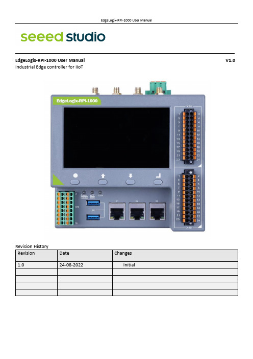
———————————————————————————————————————————EdgeLogix-RPI-1000 User Manual V1.0 Industrial Edge controller for IIoTExplanation of symbols usedThe following symbols are used in these instructions:NOTENOTE indicates tips, recommendations and useful information on specific actionsand facts.NOTICENOTICE indicates a situation which may lead to property damage if not avoided.CAUTIONCAUTION indicates a dangerous situation of riskContents1.Introduction (1)1.1 Features (1)1.2 Interfaces summary (2)1.2.1 Front view (2)1.2.2 Top view (3)1.3 Product label (4)1.4 Block Diagram (5)2.Installation and Wiring (6)2.1 Mounting (6)2.2 Connectors and Interfaces (7)2.2.1 Power supply (7)2.2.2 Left connector (8)2.2.3 Connectors of Signal Board (10)2.2.4 HDMI (11)2.2.5 Ethernet (12)2.2.6 USB HOST (12)2.2.7 Console (USB TYPEC) (12)2.2.8 LED (13)2.2.9 SMA Connector (14)2.2.10 SIM card slot (14)2.2.11 LCD panel and keyboard (15)2.3 GPIO Multiplex (16)2.4 Mainboard (17)2.4.1 Mini PCIe (18)2.4.1.1 Mini-PCIe 1 (19)2.4.1.2 Mini-PCIe 2 (20)2.4.2 PCIe subsystem (21)2.4.3 LCD board (21)2.4.4 Signal board (21)3.Drivers and Programming (21)3.1 LED (21)3.2 Serial Port (RS232 and RS485) (21)3.3 Cellular over Mini-PCIe (22)3.4 WDT (24)3.4.1 Block Diagram of WDT (24)3.4.2 How it works (25)3.5 RTC (25)3.5.1 Wiring (25)3.5.2 How it works (25)3.6 LoraWAN over Mini-PCIe (26)3.7 Signal board (26)4.Software Basics (26)5.Applications (26)6.Electrical specifications (26)7.Mechanical (26)1.IntroductionEdgeLogix-RPI-1000, modular, open-architecture edge controllers manage complex interfaces across assets and devices or into the cloud directly, with legacy and next generation industry control system. EdgeLogix-RPI-1000 provides performance and scalability for a wide range of industrial applications, including motion control, networking, IO and IIoT in a compact model, as while as the advantages of traditional IEC-61131-3 programming with the flexibility of Linux.The EdgeLogix-RPI-1000 Series covers all the functions required of logic computing, including easy operation and compatibility with a variety of control and measurement applications. This flexible device for ultra-reliable measurement and control of industry users the customized logic and control needed to meet application requirements. Industry-leading configurability and programmability fulfill standard to complex requirements while secure, built-in flow measurement calculations make it easier than ever to prove compliance. In addition, cloud-enabled functionality for licensing simplifies day-to-day operations. Digitally transform your operation by streamlining complex processes with the agile, intuitive EdgeLogix. This new controller is also p art of Seeed Studio’s next-generation EdgeLogix Series measurement and control platform that offers a common set of configuration tools, to expedite setup and facilitate commonly performed tasks.1.1 Features•Rugged, reduced-maintenance hardware•High isolation, surge, and short circuit protection•Open architecture support custom programming•Ethernet, I/O ,4G/LTE, CANopen and Modbus bridging•Natively Supports Modbus & CANopen Protocols•Cloud Connectivity to IIoT Cloud Platforms•Display for commissioning and diagnostics•IEC 61131-3 compliant programs support (under developing).•Flexible of local BUS extension•Neural Processing Unit (NPU) enables Artificial Intelligence for automation•Wide power supply from 10.8 to 36V DCThese features make the EdgeLogix designed as a cost-effective controller that provides the functions required for a variety of field automation applications. The EdgeLogix monitors, measures, and controls equipment in a remote environment. It is ideal for applications requiring flow computation; Proportional, Integral, and Derivative (PID) control loops; logic sequencing control; and a gateway with flexible wireless and field sensors expansion.1.2 Interfaces summary1.2.1Front view1. 4.3-inch LCD panel2.X30, up connector of Signal Board3.X40, down connector of Signal Board4.X3, Ethernet port 35.X2, Ethernet port 26.X1, Ethernet port 17.Dual USB 2.0 port8.X10, Left connector, Multi-Func phoenix connector9.Key board10.3x dual color LED1.2.2Top view1.Antenna A42.Antenna A33.Antenna A24.Antenna A15.HDMI port to monitor6.LocalBUS port7.Main power supply8.Console of Type-C9.TF card slot10.SIM card slot1.3 Product label1.4 Block DiagramThe processing core of the EdgeLogix-RPI-1000 is a Raspberry CM4 board. A customized carrier board implements the specific features. Refer to next figure for the block diagram.2.Installation and Wiring2.1 MountingThe 35mm DIN-rail mount is the primary method, as while as the wall mount.• The entire power supply must be disconnected and electrostatic discharge must take place on the housing or ground connection before removing any covers or components from the device and installing or removing any accessories, hardware or cables.• Remove the power cable from the device.2.2 Connectors and Interfaces2.2.1Power supplyConnect the device to the voltage supply according to the following figure.1.24V, main power supply+2.GND, main power supply-3.EARTH, connect to earth2.2.2Left connectorLeft connector is a Multi-Func phoenix connector.NOTE 1:24awg to 16awg cable are suggested.NOTE 2:All RS485 signals are isolated with other signals. NOTE 3: All DO and DI signals are isolated.◆Characteristics of Isolated RS485 Interface⚫Can used as Modbus/RTU Master or Modbus/RTU Extension .⚫Supported Function Codes: #01, #02, #03, #04, #05, #06, #07, #0F, #10 .⚫Maximum 32 devices on bus (1 master and 31 extensions) .⚫Built-in asymmetrical protection against transient voltages resulting from electro-static discharge (ESD), electrical fast transients (EFT), and lighting.⚫Terminal resistor of 120 OHM has been installed default.◆Characteristics of RS232 Interface⚫The RS-232 serial interface communication standard has been in use for many⚫years. It is one of the most widely used connections for serial data transmitting⚫because it is simple and reliable.⚫The RS232 serial interface standard still retains its popularity and remains in widespread⚫use. It is still found on some computers and many interfaces, often being⚫used for applications ranging from data acquisition to supply a serial data communication⚫facility in general computing environments.⚫The interfaces intended to operate over distances of up to 15 meters.◆Characteristics of I/O Interface⚫DC voltage for input is 24V (+- 10%).⚫DC voltage for output should be under 60V, the current capacity is 500ma.⚫Channel 1 and channel 2 of input are isolated to each other.⚫Channel 1 and channel 2 of output are isolated to each other.2.2.3Connectors of Signal BoardThe signal board is fully isolated with main PCB board. It contains X30, X40 and X6 of connectors.X30 is used as DIO signals. The following figure shows details of wiring.X30 wiring◆Characteristics of DI and DO Interface⚫The power supply of DI should be 5-36V DC,24V default.⚫The power supply of DO should be 10.8-60V DC,24V default, and the current of each channel is 1A.X40 wiringNOTE: All “GND” signals are connected together and isolated with main power island.X6 connectorX6 connector is used for Local Bus extensions, such as DO, DI, AO, AO or RTD module can be connected in this bus.2.2.4HDMIDirectly connected to the Raspberry PI CM4 board with TVS array. The default display in EdgeLogix-RPI-1000conforms to the HDMI standard.2.2.5EthernetEthernet interface is same as Raspberry PI CM4,10/100/1000-BaseT supported, available through the shielded modular jack. Twisted pair cable or shielded twisted pair cable can be used to connect to this port.2.2.6USB HOSTThere are two USB interfaces at the connector panel. The two ports share the same electronic fuse. NOTE: Max current for both ports is limited to 1600ma.2.2.7Console (USB TYPEC)CM4 USB-UART Bridge USB TYPECThe design of console used a USB-UART converter, most OS of the computer have the driver, if not, the link below may be useful:/products/CH9102.htmlThis port is used as a Linux console default. You can log into the OS use the settings of 115200,8n1(Bits: 8, Parity: None, Stop Bits: 1, Flow Control: None).A terminal program such as putty is needed, too.The default user name is pi and password is raspberry.2.2.8LEDEdgeLogix-RPI-1000 use three green/red dual color LED as outside indicators.LED1: green as power indicator and red when 4G/LTE active.LED2: green as signal indicator and red as user programmable led connected to GPIO13, high active and programmable.LED3: LED3 is used for Local BUS, it is to be defined in future. It indicates the communication between main and extensions.2.2.9SMA ConnectorThere are four SMA Connector holes for antennas. The antenna types are very depended on what modules fitted into the Mini-PCIe socket. The A1 is recommended for WI-FI signal from CM4 module and A2 for cellular.NOTES:The functions of the antennas are not fixed, maybe adjusted to cover other usage.2.2.10SIM card slotThe sim card is only needed in cellular (4G/LTE or others based on cellular technology) mode.NOTES: O nly Standard Sim card is accepted, pay attention to the card size.2.2.11 LCD panel and keyboardThe LCD display allows you to view meter data and perform basic configuration, or used for system diagnosis.◆LCD panelThe LCD display has the resolution of 800x480 pixel. It has an individual display controller connector to main CPU (Raspberry PI CM4) via SPI interface. The program model is full open to customers.SPI RGBKey x 4The backlight dims after a defined period of inactivity. When the meter detects an unacknowledged activehigh priority alarm, the display flashes until the alarm is acknowledged. ◆Home buttonPressing the home button takes you to the associated menu screen. If you are in a data screen, pressing the home button takes you to the display menu, and pressing home twice takes you to the summary display screen. If you are in a setup screen, pressing home takes you to the setup menu, and pressing home again takes you to the display menu. Function keys◆ Arrow buttonThe two arrow keys can be used for navigation and selection.◆ Enter buttonNormally used as confirm or Enter.2.3 GPIO MultiplexOverview of the GPIO usage from CM4, most of the GPIO have the fixed function as list.The Mainboard spans the inner width of the device and has outward-facing ports on frond and up sides. It is mounted to the heat sink with four M3x6 pan head screws.EdgeLogix-RPI-1000 itself has two mini-PCIe card slots, one for 4G/LTE with SIM cad support and the other has SPI signals.The orange area is the rough PCIe add-on card position, only one M2x5 screw is needed.The table below show all the signals. Full size Mini-PCIe card are supported.NOTE 1: All blank signals are NC (not connect).NOTE 2: 4G_PWR is the individual power supply for Mini-PCIe card. It can be shut down or turn on by the GPIO22 of CM4, the control signal is high active.NOTE 3:4G_LED signal is connected to LED1 internallyNOTE 1: SPI1 signals are used only for LoraWAN card, such as SX1301, SX1302. NOTE 2:All PCIe signals are optional.2.4.2PCIe subsystemThe CM4 itself has only on channel of PCIe 1x. The design of EdgeLogix-RPI-1000 use a switch to extern 3 NIC cards and one optional channel to mini PCIe 2 slots.2.4.3LCD board2.4.4Signal board3.Drivers and Programming3.1 LEDThe is a LED used as user indicator, refer to 2.2.8.Use LED2 as a mexample to test the function.$ sudo -i #enable root account privileges$ cd /sys/class/gpio$ echo 13 > export #GPIO21 which is user LED of LED2$ cd gpio13$ echo out > direction$ echo 1 > value # turn on the user LED, HIGH activeOR$ echo 0 > value # turn off the user LED3.2 Serial Port (RS232 and RS485)There are two individual serial ports in the system. The /dev/ttyACM1 as RS232 port and/dev/ttyACM0 as RS485 port. Use RS232 as a example.$ python>>> import serial>>> ser=serial.Serial('/dev/ttyACM1',115200,timeout=1)>>> ser.isOpen()true>>> ser.isOpen()>>> ser.write('1234567890')103.3 Cellular over Mini-PCIe◆Use Quectel EC20 as a example and follow the steps:1.Insert the EC20 into Mini-PCIe socket and sim card in related slot, connect the antenna.2.Log in the system via console use pi/raspberry.3.Turn on the power of Mini-PCIe socket and release the reset signal.$ sudo -i #enable root account privileges$ cd /sys/class/gpio$ echo 22 > export #GPIO22 which is POW_ON signal$ echo 5 > export #GPIO5 which is reset signal$ cd gpio22$ echo out > direction$ echo 1 > value # turn on the power of Mini PCIeAND$ cd gpio5$ echo out > direction$ echo 1 > value # release the reset signal of Mini PCIeNOTE: Then the LED of cellular is start to flash.4.Check the device:$ lsusb$ Bus 001 Device 005: ID 2c7c:0125 Quectel Wireless Solutions Co., Ltd. EC25 LTE modem ……$ dmesg$……[ 185.421911] usb 1-1.3: new high-speed USB device number 5 using dwc_otg[ 185.561937] usb 1-1.3: New USB device found, idVendor=2c7c, idProduct=0125, bcdDevice= 3.18 [ 185.561953] usb 1-1.3: New USB device strings: Mfr=1, Product=2, SerialNumber=0[ 185.561963] usb 1-1.3: Product: Android[ 185.561972] usb 1-1.3: Manufacturer: Android[ 185.651402] usbcore: registered new interface driver cdc_wdm[ 185.665545] usbcore: registered new interface driver option[ 185.665593] usbserial: USB Serial support registered for GSM modem (1-port)[ 185.665973] option 1-1.3:1.0: GSM modem (1-port) converter detected[ 185.666283] usb 1-1.3: GSM modem (1-port) converter now attached to ttyUSB2[ 185.666499] option 1-1.3:1.1: GSM modem (1-port) converter detected[ 185.666701] usb 1-1.3: GSM modem (1-port) converter now attached to ttyUSB3[ 185.666880] option 1-1.3:1.2: GSM modem (1-port) converter detected[ 185.667048] usb 1-1.3: GSM modem (1-port) converter now attached to ttyUSB4[ 185.667220] option 1-1.3:1.3: GSM modem (1-port) converter detected[ 185.667384] usb 1-1.3: GSM modem (1-port) converter now attached to ttyUSB5[ 185.667810] qmi_wwan 1-1.3:1.4: cdc-wdm0: USB WDM device[ 185.669160]qmi_wwan 1-1.3:1.4 wwan0: register 'qmi_wwan' at b-1.3, WWAN/QMI device,xx:xx:xx:xx:xx:xxxx:xx:xx:xx:xx:xx is the MAC address.$ ifconfig -a……wwan0: flags=4163<UP,BROADCAST,RUNNING,MULTICAST> mtu 1500inet 169.254.69.13 netmask 255.255.0.0 broadcast 169.254.255.255inet6 fe80::8bc:5a1a:204a:1a4b prefixlen 64 scopeid 0x20<link>ether 0a:e6:41:60:cf:42 txqueuelen 1000 (Ethernet)RX packets 0 bytes 0 (0.0 B)RX errors 0 dropped 0 overruns 0 frame 0TX packets 165 bytes 11660 (11.3 KiB)TX errors 0 dropped 0 overruns 0 carrier 0 collisions 05.How to use AT command$ miniterm --- Available ports:--- 1: /dev/ttyAMA0 'ttyAMA0'--- 2: /dev/ttyttyACM0 'CP2105 Dual USB to UART Bridge Controller'--- 3: /dev/ttyttyACM1 'CP2105 Dual USB to UART Bridge Controller'--- 4: /dev/ttyUSB0 'Android'--- 5: /dev/ttyUSB1 'Android'--- 6: /dev/ttyUSB2 'Android'--- 7: /dev/ttyUSB3 'Android'--- Enter port index or full name:$ miniterm /dev/ttyUSB3 115200Some useful AT command :⚫AT //should return OK⚫AT+QINISTAT //return the initialization status of (U)SIM card, the response should be 7⚫AT+QCCID //returns the ICCID (Integrated Circuit Card Identifier) number of the (U)SIM card6.How to dial$su root$ cd /usr/app/linux-ppp-scripts$./quectel-pppd.shThen the 4G led is flashing.If success, the return like this:7.Add the router path$ route add default gw 10.64.64.64 or your gateway XX.XX.XX.XXThen have a test$ ping 3.4 WDT3.4.1Block Diagram of WDTThe WDT module have three terminals, input, output and LED indicator.Note:3.4.2How it works1.System POWER ON.2.Delay 200ms.3.Send WDO a negative pulse with 200ms low level to reset the system.4.Pull up WDO.5.Delay 120 seconds while the indicator flashing (typical 1hz).6.Turn off the indicator.7.Wait for 8 pulses at WDI to active WDT module and light the LED.8.Get Into WDT-FEED mode, at least one pulse should be feed into WDI in at least every 2 seconds, ifnot, the WDT module should output a negative pulse to reset the system.9.Goto 2.3.5 RTC3.5.1WiringThe chip of RTC is PCF8563 or other compatible. It is mounted on the system I2C bus.The OS itself has the driver inside, only we need are some configurations.3.5.2How it worksOpen /etc/rc.local AND add 2 lines:echo " pcf8563 0x51" > /sys/class/i2c-adapter/i2c-1/new_devicehwclock -sThen reset the system and the RTC is working.Note:1.make sure the i2c-1 driver point is open, and the point is closed default.2. the estimated backup time of the RTC is 10 days.3.6 LoraWAN over Mini-PCIe3.7 Signal board4.Software Basics5.Applications6.Electrical specifications6.1 Power consumptionThe power consumption of the EdgeLogix-RPI-1000 strongly depends on the application, the mode of operation and the peripheral devices connected. The given values have to be seen as approximate values. The following table shows power consumption parameters of the EdgeLogix-RPI-1000:Note: On condition of power supply 24V, no add-on card in sockets and no USB devices.6.2 Power supply7.Mechanical。
poweredge-m1000e用户手册

Dell PowerEdge M1000e 机柜用户手册管制型号: BMX01注、小心和警告注: “注”表示可以帮助您更好地使用计算机的重要信息。
小心: “小心”表示可能会损坏硬件或导致数据丢失,并说明如何避免此类问题。
警告: “警告”表示可能会造成财产损失、人身伤害甚至死亡。
© 2013 Dell Inc. 保留所有权利。
本文中使用的商标: Dell™、Dell 徽标、Dell Boomi™、Dell Precision™、 OptiPlex™、Latitude™、PowerEdge™、PowerVault™、PowerConnect™、OpenManage™、EqualLogic™、Compellent™、KACE™、FlexAddress™、Force10™、Venue™和 Vostro™是 Dell Inc. 的商标。
Intel®、Pentium®、Xeon®、Core®和 Celeron®是 Intel Corporation 在美国和其他国家或地区的注册商标。
AMD®和 AMD Opteron™、AMD Phenom™以及 AMD Sempron™是 Advanced Micro Devices, Inc.的注册商标或商标。
Microsoft®、Windows®、Windows Server®、Internet Explorer®、MS-DOS®、Windows Vista®和 Active Directory®是 Microsoft Corporation 在美国和/或其他国家或地区的商标或注册商标。
Red Hat®和 Red Hat® Enterprise Linux®是 Red Hat、Inc. 在美国和/或其他国家或地区的注册商标。
RG-EG系列出口网关RGOS10.3(4b7)版本WEB配置手册

在设置完应用的设置后,单击“下一步”进入用户配置页面,如下图所示:
4
Web 配置指导
用户可以通过.XLS 文件导入用户信息。在设置完用户的设置后,单击“下一步”进入 完成配置页面,如下图所示:
点击 完成配置 按钮。
5
Web 配置指导
1.2.1.2 网关模式下的快速配置
点击
进入网络配置:
网桥模式下的接口配置,先配置管理口,管理口是用户管理员用户直接管理设备的入 口;设备支持 双入双出 线路,你可以配置两条线路并对每条线路分别进行管理。
总流量柱状图监控的是 当前所在接口(线路)的总流量,如果当前总流量的值达到接口 (线路)的总流量的 90% 则柱状图会显示黄色警告,警告说明当前总流量过高,可 能会影响到内网网络流畅;这个时候就需要管理员查看流量消耗在那里了,是否是利 用于工作还是被滥用了。
按流量排序用户:选择
后用户将按照所选的方式排序。
15
Web 配置指导
内存使用率报表:审计一天内存使用情况,把握内存使用走势;同 CPU 一样以表格 和曲线图两种方式展现。
16
Web 配置指导
1.4.2 流量管理
1.4.2.1 用户流量分析
按照接口(线路)分析用户的流量,实时监控用户的当前流量状况和使用应用详细情况, 支持对用户流量进行简易调整,从而达到快速限制流量过高的用户。
1.1 进入 Web 管理
在浏览器地址栏中输入EG出口网关设备的内网口或外网口或是管理口的IP地址,您的 PC的IP地址必须与EG设备的IP地址在同一网段。复位或初始情况下,在浏览器中输 入默认地址:http://192.168.1.1。 网关模式下 PC 机连接 Gi0/0 端口;网桥模式下连接 MGMT 口。 系统初始页面如下:
COM100D COM100E 智能能通讯箱 用户手册说明书

3.1 功能描述....................................................................................................... 5 3.1.1 产品简介 ............................................................................................. 5 3.1.2 组网应用 ............................................................................................. 5
COM100D/COM100E智能通讯箱用 户手册COM100D_E-UCN-Ver11-
202201
COM100D_E-UCN-Ver11-202201
COM100D/COM100E 智能通讯箱 用户手册
目录
1 关于本手册 ......................................................................... 1
8 附录 ................................................................................................................. 30
RG-iS16FSAS用户安装手册

人体产生的静电会损坏电路板上的静电敏感元器件。在接触机箱内的电路 板、芯片等部件之前,为防止人体静电损坏敏感元器件,必须佩戴防静电手 环,并将防静电手环的另一端良好接地。
ห้องสมุดไป่ตู้
�
手持电路板时只能接触边缘, 从防静电袋或产品取出电路板后, 请将电路板 侧面朝上放置在无静电的接地表面上。请勿将电路板在任何表面上滑动。
各类标志
本书采用以下醒目标志来表示在操作过程中应该特别注意的地方, 这些标志的意义 1
如下: 1 . 红色底纹,表示警告、注意,提醒操作中须小心注意的事项。
� � ☺
符号
警告 2 . 黄色底纹,表示约定、参考,对正文的补充说明。
说明 3 . 绿色底纹,表示建议、小窍门、推荐的操作方法。
建议
< >:表示按键名称、按钮名称以及操作员从终端输入的信息,如<Enter >、< a>分别表示回车、小写字母 a。 [ ] :表示人机界面、菜单条、数据表和字段名等,其中多级菜单用“→”隔开。 如[檔→新建]多级菜单,表示[檔]菜单下的[新建]子菜单。
1434343434连接扩柜连接扩柜连接扩柜连接扩柜展展展展341341341341连接多台扩柜连接多台扩柜连接多台扩柜连接多台扩柜展展展展342342342342主柜接口主柜接口主柜接口主柜接口15343343343343扩柜接口扩柜接口扩柜接口扩柜接口展展展展35353535管理管理管理管理线连接线连接线连接线连接通过一根网线连接到交换机上存储默认ip地址是1921681100用户名
� � � �
宽敞的安装场所。 螺丝刀。 网线。 防静电设备或方法。
3.2 开箱检查
检查设备是否完好。 检查附件是否齐全。
安装 3.3 设备 设备安装
锐捷 Reyee RG-EW 系列路由器 Web 配置指南说明书

Ruijie Reyee RG-EW Series Routers Web-Based Configuration GuideCopyright StatementRuijie Networks©2021Ruijie Networks reserves all copyrights of this document. Any reproduction, excerption, backup, modification, transmission, translation or commercial use of this document or any portion of this document, in any form or by any means, without the prior written consent of Ruijie Networks is prohibited.Exemption StatementThis document is provided “as is”. The contents of this document are subject to change without any notice. Please obtain the latest information through the Ruijie Networks website. Ruijie Networks endeavors to ensure content accuracy and will not shoulder any responsibility for losses and damages caused due to content omissions, inaccuracies or errors.PrefaceThank you for using our products.AudienceThis manual is intended for:●Network engineers●Technical support and servicing engineers●Network administratorsObtaining TechnicalAssistance●Ruijie Networks Website: https:///●Technical Support Website: https:///support ●Case Portal: https://●Community: https://●Technical Support Email: *****************************●Skype: *****************************Related DocumentsConventionsThis manual uses the following conventions:Configuration Guide Overview 1 OvervieweWeb is a Web-based network management system that manages or configures devices. You can access eWeb via browsers such as Google Chrome.Web-based management involves a Web server and a Web client. The Web server is integrated in a device, and is used to receive and process requests from the client, and return processing results to the client. The Web client usually refers to a browser, such as Google Chrome IE, or Firefox.1.1 ConventionsIn this document, texts in bold are names of buttons (for example, OK) or other graphical user interface (GUI) elements (for example, ARP List).12 Configuration Guide2.1 PreparationScenarioAs shown in the figure below, an administrator can access the device from a browser and configure the device through the eWeb management system.Figure 2-1-1 Data Exchange PrincipleDeliver or requestcommandsthrough AJAX.Administrator Return dataWebserviceDeviceDeployment↘Configuration Environment RequirementsClient requirements:●An administrator can log into the eWeb management system from a Web browser to manage devices. The client refersto a PC or some other mobile endpoints such as laptops or tablets.●Google Chrome, Firefox, IE10.0 and later versions, and some Chromium-based browsers (such as 360 ExtremeExplorer) are supported. Exceptions such as garble or format error may occur if an unsupported browser is used.●1024 x 768 or a higher resolution is recommended. If other resolutions are used, the page fonts and formats may not bealigned and the GUI is less artistic, or other exceptions may occur.●The client IP address is set in the same LAN network as the device IP address, such as 192.168.110.X. The subnetmask is 255.255.255.0. Alternatively, you can set the IP assignment mode to Obtain an IP address automatically or enter into the address bar of the browser to access eWeb.The default gateway is device management address 192.168.110.1.Server requirements:●The device is enabled with Web service (enabled by default).23The device is configured with a management IP address (Default: 192.168.110.1). You can enter http://192.168.110.1to access the eWeb management system.To log into the eWeb management system, open the Google Chrome browser, and enter http://192.168.110.1 into the address bar, and pressEnter .F igure 2-1-2 Login PageEnter the password and click Login .2.2 WizardYou will enter the Wizard page without login at initial setup.2.2.1 Welcome PageThe welcome page will appear when you configure the device for the first time.Figure 2-2-1 Welcome PageThe network status will be displayed when you configure the device for the second time. Figure 2-2-2 Wizard Page4If the network are configured with repeaters, their number is displayed. (In the above figure, X32G-PRO is the primary router.)2.2.2 Network SettingsWhen the device is not connected via network cables, the following page is displayed.Figure 2-2-3 Network Settings52.2.2.1 Wireless RepeatingTo scan nearby Wi-Fi, click Wireless Repeating.Figure 2-2-7 Wi-Fi List6Figure 2-2-8 Wireless Repeating 1Enter the Wi-Fi password of the primary router (This item will not be displayed if the primary router Wi-Fi is open).Click Next to set the wireless information and management password of the device (This configuration applies to only new devices).Figure 2-2-9 Wireless Repeating 2Figure 2-2-10 Completing Wireless Repeating Configuration2.2.2.2 Wired RepeatingWhen the device is connected via network cables, the wired repeater can be configured. (This option is ready for new devices only).Figure 2-2-11 Wired RepeatingClick Check, and enter the local router SSID, password and management password. Click Save to complete the configuration.Figure 2-2-12 Wired Repeater PageFigure 2-2-13 Completing Configuration2.2.2.3 InternetWhen the device is not configured with the repeating configuration, you can access the Internet through the following means: If the device fails to access the Internet, the system will check IP assignment automatically. It is recommended to select DHCP.Figure 2-2-14 Normal ConnectionFigure 2-2-15 DHCPFigure 2-2-16 PPPoEFigure 2-2-17 Static IP2.2.3 WiFi SettingsThis module allows you to configure the SSID, WiFi password and management password.Figure 2-2-18 WiFi Settings2.2.4 FinishAfter the configuration is delivered, click Finish to enter the homepage. Figure 2-2-19 FinishNote: For a new device which is configured via a mobile client, the automatically pop-up page does not display Finish. Click Add Router.Figure 2-2-20 Add Router2.3 GUI2.3.1 Phone-Based GUIThe system switches between the phone-based GUI and PC-based GUI according to the screen width and browser type. The phone-based GUI is more concise.Figure 2-3-1 Phone-Based GUI2.3.2 PC-Based GUIClick Pro in the upper right corner of phone-based GUI to switch over to the PC-based GUI. The PC-based GUI provides more configuration items. For details, see eWeb Configuration .Figure 2-3-2 PC-Based GUI3 eWeb ConfigurationThis chapter introduces the features on the PC-based GUI.3.1 OverviewThe Overview page displays the device details, WiFi and interface details.Figure 3-1 Overview3.2 ClientsThe Clients module allows you to bind the static IP, manage blocked time and block WLAN clients. Figure 3-2-1 Online ClientsFigure 3-2-2 Blocked Time ManagementFigure 3-2-3 Add RuleBind the Static IP AddressFigure 3-2-4 Bind Static IP AddressYou can convert a dynamic IP address to a static IP address by clicking Unbinded. In the displayed dialog box, configure settings and click OK.3.3 InternetThe Internet module allows you to select an IP assignment mode.Figure 3-3-1 Internet3.4 WiFiThe WiFi module allows you to configure WiFi settings. Figure 3-4-1 WiFi Settings3.5 More3.5.1 Basics3.5.1.1 WANThe WAN module allows you to configure WAN settings. There are three IP assignment modes available: Static IP Address, DHCP and PPPoE.Figure 3-5-1 WAN Settings3.5.1.2 LANThe LAN module contains LAN Settings, DHCP Clients, Static IP Addresses and DNS Proxy.3.5.1.2.1 LAN SettingsThe LAN module allows you to set the IP address of the LAN port and DHCP status.Figure 3-5-2 LAN Settings3.5.1.2.2 DHCP ClientsThe DHCP Clients page displays DHCP clients.Figure 3-5-3 DHCP ClientsClick Convert to Static IP in the Action column to convert a DHCP-assigned IP address to a static IP address. Alternatively, select DHCP-assigned IP addresses and click Batch Convert to convert more than one IP address.3.5.1.2.3 Static IP AddressesThe Static IP Addresses module allows you to add, delete and edit static IP addresses.Figure 3-5-4 Static IP AddressesClick Add to add a static IP address manually. In the displayed dialog box, configure settings and click OK.Figure 3-5-5 Add Static IP Address3.5.1.2.4 DNS ProxyThe DNS Proxy module allows you to configure DNS proxy settings.Figure 3-5-6 DNS Proxy3.5.1.1 IPTV/VLANThe IPTV/VLAN Settings module allows you to configure IPTV/VLAN settings. Figure 3-5-7 IPTV/VLAN3.5.1.2 IPv6 AddressThe WAN Settings module allows you to configure WANv6 settings. Figure 3-5-7 IPv6 AddressFigure 3-5-8 LAN SettingsFigure 3-5-9 DHCPv6 Clients3.5.1.3 RepeaterThe Repeater module displays the current mode and the other available modes.Figure 3-5-10 Router ModeFigure 3-5-11 Wired RepeaterFigure 3-5-12 Wireless RepeaterFigure 3-5-13 Wi-Fi ListSet a new Wi-Fi password (optional). Figure 3-5-14 Wi-Fi Password3.5.2 Wireless3.5.2.1 WiFi3.5.2.1.1 WiFi SettingsThe WiFi Settings module allows you to configure the primary WiFi.Figure 3-5-15 WiFi Settings3.5.2.1.2 Guest WiFiThe guest WiFi is disabled by default. You can enable guest WiFi on this page or homepage.AP isolation is enabled by default and cannot be edited.Set a schedule, and the guest WiFi will be enabled only during this period time. When the time expires, the guest WiFi will be disabled.Figure 3-5-16 Guest WiFiFigure 3-5-17 Enable Guest WiFi3.5.2.1.3 Smart WiFiThe Smart WiFi module allows to configure the smart WiFi.Figure 3-5-18 Smart WiFi3.5.2.1.4 Healthy ModeThe Healthy Mode module allows you to enable health mode and set a schedule.Figure 3-5-19 Healthy Mode3.5.2.2 Blocked ClientsThe Blocked Clients module allows you to add, edit or delete blocked clients.Click Delete in the Action column to delete a blocked client. Alternatively, select target clients and click Delete Selected to delete more than one blocked clients.Figure 3-5-20 Blocked ClientsClick Add to add a blocked Clients. In the displayed dialog box, configure settings and click OK.Figure 3-5-21 Add Blocked Client。
- 1、下载文档前请自行甄别文档内容的完整性,平台不提供额外的编辑、内容补充、找答案等附加服务。
- 2、"仅部分预览"的文档,不可在线预览部分如存在完整性等问题,可反馈申请退款(可完整预览的文档不适用该条件!)。
- 3、如文档侵犯您的权益,请联系客服反馈,我们会尽快为您处理(人工客服工作时间:9:00-18:30)。
StorageManager 配置
2.2.3 磁盘组
本章节主要包括以下内容: 磁盘组属性 新建磁盘组 修改和删除磁盘组 磁盘漫游
磁盘组属性
在“磁盘组”选项中的“磁盘组属性”选项里面,显示了当前 RG-iS1000E 系统中的磁 盘数,空闲磁盘数,以及磁盘组数。
10 / 67
StorageManager 配置
在“虚拟磁盘”选项中,“虚拟磁盘属性”列出了当前虚拟磁盘个数和磁盘组数。在左 侧的菜单栏里面可以点击具体的虚拟磁盘查看详细信息。 RG-iS1000E 具有 IP SAN 和 NAS 一体化属性,因此虚拟磁盘会有两种,一种是供 iSCSI 使用,一种供 NAS 使用。
新建虚拟磁盘
在“虚拟磁盘属性”里面选择“新建虚拟磁盘”来创新一个新的虚拟磁盘。需要输入虚 拟磁盘的名称,选择在哪一个磁盘组上创建虚拟磁盘,以及虚拟磁盘的容量(单位是 MB)。在虚拟磁盘类型中需要选择 iSCSI 或者 NAS。
StorageManager 配置
中至少应该设置一块热备盘。
修改和删除磁盘组
点击左侧列表中选定的磁盘组,会进入该磁盘组的属性界面,可以完成修改和删除磁盘 组工作。
删除磁盘组操作时,系统会提示你是否确认“删除”,如果该磁盘组在使用中,将不能 被删除。
磁盘漫游
a
RG-iS1000E 支持在同一控制器上将物理磁盘从一个电缆连接或背板插槽移动到另一个 电缆连接或背板插槽。控制器将自动识别重新定位的物理磁盘并按照逻辑将其置于作为 磁盘组一部分的适当的虚拟磁盘中。
本书约定
命令行格式约定
命令行字体采用用 Arial,具体相关格式意义如下: 粗体:命令行关键字(命令中保持不变必须照输的部分)采用加粗字体表示。 斜体:命令行参数(命令中必须由实际值进行替代的部分)采用斜体表示 [ ] :表示用[ ] 括起来的部分,在命令配置时是可选的。 { x | y | ... }:表示从两个或多个选项中选取一个。 [ x | y | ... ]:表示从两个或多个选项中选取一个或者不选。 //:由双斜杠开始的行表示为注释行。
15 / 67
StorageManager 配置
2.2.5 iSCSI
本章节主要包括以下内容: iSCSI 管理界面 iSCSI 权限管理 iSCSI 连接状态
2.1.2 登录界面
RG-iS1000E 的登录界面如图所示。
4 / 67
StorageManager 配置 StorageManager 的用户名是:admin,密码是:123456。
2.2 选项说明
主要介绍 StorageManager 中各选项的功能及使用方法以及注意事项。
本章节主要包括以下内容:
5 / 67
StorageManager 配置
退出
登录进入管理界面以后,右上角的“退出”可以退出 RG-iS1000E 的管理界面。
关闭
登录进入管理界面以后,右上角的“关闭”,可以将 RG-iS1000E 系统正常关机。 6 / 67
a
StorageManager 配置
当关闭 RG-iS1000E 时,必须保证主机端没有正在使用 RG-iS1000E 的程序或者设备, 否则关闭 RG-iS1000E 会导致应用中断或者数据丢失。
特性 产品规格
1.1.1 特性
存储处理器使用多核 Xeon 处理器,Fully Buffered DDR2 内存,提高了产品的性能。 拥有 2 个 iSCSI 1Gb 主机信道,允许使用现有的以太网网络传输 SCSI 指令和数据。 在 2U 空间可以灵活安装 12 个 SAS/SATA-Ⅱ 3.5 英寸硬盘,同时支持 DAS(Direct Access Storage)和 SAN(Storage Area Network)连接,具有极高的可用性、可靠性 和可维护性。 提供 NAS 存储服务,支持 iSCSI、CIFS、NFS、HTTP 等多种协议, 可根据需要灵活配置应用存储环境,为企业用户构建低成本的存储方案。 可加载第三方应用程序,将用户的应用和存储融合在一起 电源模块+散热模块、磁盘托架支持热插拔。
2 / 67
配置综述
1.1.1 产品规格
外形规格 CPU 系统缓存 主机通道 支持传输协议 支持网络文件系统 支持网络客户端 磁盘通道 扩展柜 LUN 数量 主机连接数 存储容量
磁盘数 硬盘规格
RAID 级别 热备盘 IOPS 带宽 管理软件
2U12 盘位机架式 标配一颗 Intel Xeon 双核 1.6GHz 处理器,最大两颗 CPU 标配 2GB Fully Buffered DDR2 内存,最大扩展到 16GB 标配 2 个 1Gb 以太网接口,可扩展至 4 个主机接口 CIFS、NFS、iSCSI CIFS/NFS Windows/Linux SAS 2U12 盘位 JBOD,最大 3 个 1024 个 最大 128 个 SAS:单柜最大容量 3.6TB(300GB*12),系统最大 14.4TB SATA:单柜最大容量 12TB(1TB*12),系统最大 48TB 48 个 3.5" 146/300GB 15k RPM SAS3.0 磁盘 3.5" 500/750GB/1TB 7200 RPM SATAⅡ磁盘 RAID0、1、10、5 支持,阵列后台自动重建 ≥90000(4 主机端口) ≥400MB/S(4 主机端口)
本章介绍通过 StorageManager 来对 RG-iS1000E 进行配置的方法。 本章节主要包括以下内容:
初始设置 选项说明
2.1 初始设置
本章节主要包括以下内容: 默认设置 登录界面
2.1.1 默认设置
RG-iS1000E 的默认设置中,eth0 的真实 IP 地址为:192.168.1.10,eth1 的真实 IP 地址 为:192.168.1.11,连接好网络,RG-iS1000E 启动完成以后,输入以上 IP 地址即可登录 RG-iS1000E 的管理界面。 RG-iS1000E 默 认 组 IP 设 置 为 192.168.1.10 , 我 们 也 可 以 在 浏 览 器 内 直 接 输 入 “192.168.1.10”直接登录 StorageManager 配置存储(eth0 需要连接网线)。
在“系统”选项中的“硬件状态”选项里面,显示了当前 RG-iS1000E 系统中的硬件状 态和属性,包含硬盘状态信息、网络接口状态信息、电源状态信息等。将鼠标在右侧机 箱图片上的某个设备上,会自动显示出来该设备的状态和信息。 如果有未连接的网络端口或者电源工作不正常,左下角的系统状态会有警告。
8 / 67
StorManager 存储系统管理软件
1.2 配置方式
RG-iS1000E 内嵌有管理软件,用户可以直接通过浏览器登录来管理存储,使用存储提 供的所有功能,也可以通过 CLI 终端界面来对存储进行一些基本的设置。
3 / 67
StorageManager 配置
2 StorageManager 配置
日志
StorageManager 配置
在“系统”选项中的“日志”选项里面,显示了当前 RG-iS1000E 系统的日志,可以查 询、下载、清空这些日志,RG-iS1000E 默认显示最新的 500 条日志,若要查看所有日 志,需要下载日志到本地后查看。
性能状态
在“系统”选项中的“日志”选项里面,显示了当前 RG-iS1000E 系统的性能状态统计, 包含 CPU 占用率、内存占用率、网络接口的性能统计、磁盘的性能统计。“性能状态” 便于我们了解 RG-iS1000E 的工作负载以及性能表现。
各类标志
本书采用以下醒目标志来表示在操作过程中应该特别注意的地方,这些标志的意义如 下: 1 . 红色底纹,表示警告、注意,提醒操作中须小心注意的事项。
a
警告 2 . 黄色底纹,表示约定、参考,对正文的补充说明。
说明
3 . 绿色底纹,表示建议、小窍门、推荐的操作方法。
☺
建议
符号
< >:表示按键名称、按钮名称以及操作员从终端输入的信息,如<Enter>、<a>分 别表示回车、小写字母 a。
1.1 产品简介
RG-iS1000E 系列是推出的全新网络存储产品,提供 IP SAN/NAS 一体化数据存储。 RG-iS1000E 系列采用先进的设计理念和体系架构,融入 SAS、多核处理器、多协议负 载均衡等多项先进的数据处理和传输技术,保证了系统的高可用性、高性能和强大的扩 展能力。 本章节主要包括以下内容:
磁盘漫游必须将系统关闭后才可进行。 当 RAID 在进行容量扩充时,请勿进行磁盘漫游。 磁盘漫游必须在同一控制器内进行,如非必需,请勿进行磁盘漫游操作!
13 / 67
StorageManager 配置
2.2.4 虚拟磁盘
本章节主要包括以下内容: 虚拟磁盘属性 新建虚拟磁盘 修改和删除虚拟磁盘
虚拟磁盘属性
配置手册 RG-iS1000E 智能存储系统
版权声明
福建星网锐捷网络有限公司©2008 版权所有,保留一切权利。 没有经过本公司书面许可,任何单位和个人不得擅自摘抄、复制 本书内容的部分或者全部,并且不得以任何形式传播。
、
、
、
、
网锐捷网络有限公司的注册商标,不得仿冒。
、
、
都是福建星
前言
读者对象
本书适合下列人员阅读: 网络工程师 技术推广人员 网络管理员
重启、退出与关闭 系统 磁盘组 虚拟磁盘 iSCSI NAS 设置
2.2.1 重启、退出与关闭
重启
a
本章节主要包括以下内容: 重启 退出 关闭
登录进入管理界面以后,右上角的“重启”可以让 RG-iS1000E 系统重启。重新启动系 统需要几分钟时间。
当重新启动 RG-iS1000E 时,必须保证主机端没有正在使用 RG-iS1000E 的程序或者设 备,否则重启 RG-iS1000E 会导致应用中断或者数据丢失。