BAO40- UAC-5中文资料
JCB 515-40 LOADALL产品介绍说明书

You want compact size and manoeuvrability. You want a machine that works in restricted height buildings. You want excellent lift height, lift capacity and reach. Before, all of this meant a combination of skid steer, wheeled loading shovel and forklift… not now. One machine, the JCB 515-40, ticks all the boxes, opening up telehandler versatility to a whole new range of users.So how does the 515-40 do it? One word… innovation. Everything hinges on our revolutionary, off-set, single-spine chassis which has its core strength under the boom and wraps around the cab. This allows us to position the cab lower than usual providing three key benefits.First, the whole machine is low, 1.8m in fact. Second, to achieve that height we haven’t had to shrink the cab, as in some competitor machines, so there’s no compromise on comfort or space. And third, cab entry is now at low level for improved health and safety.Despite mini proportions, the 515-40 packs a real punch, in line with customer feedback which told us you want compact dimensions, with power. So this incredible innovation can lift 1.5 tonnes to 4m height, and 1 tonne across 2m for loading the opposite side of a truck.Inside greenhouses, chicken sheds, tunnels and multi-storey car parks; craned into high-rise developments; a secondary site machine alongside your full-size Loadall; rental, builders’ merchants, fruit farms, smallholdings, vineyards: the 515-40 is the mini marvel we’ve all been waiting for.Innovation at its heart At 1.8m, it’s the ultimate, go-anywhere, mini marvelSo, the 515-40 can get in where doorways or building height often prove an obstacle to other machines. The same is true of a skid steer, you say. Y es, but often a skid steer can’t give access or loading height.At the same time, the 515-40 gives shovel performance comparable to a skid steer or wheeled loading shovel. Plus, individual hydraulic wheel motors and four-wheel steer equals superb movement in the face of tight corners, pillars and narrow doorways.Where ground conditions may vary, in builders’ merchants or farmyards, for instance, four-wheel drive and good ground clearance more than copes with the challenging terrain. Add a hydrostatic transmission for easy operation, infinite speed variations and better fuel efficiency, and you have the winning formula for versatile performance and productivity.The other feature that sets the 515-40 apart from its competitors is comfort. Thanks to the chassis design, there is no compromise on cab size to achieve the 1.8m height. So the interior is spacious with superb visibility.The stable-type door allows you to shut out unpleasant conditions, or open up the top half for a little fresh air whilst still protecting the operator from mud and debris. Optional air conditioning or face level fan further enhance operator comfort. And the cab itself, with side, low-level entry, also means the 515-40 is a safer machine.You’ve got it into a tight space,now what?Incredible manoeuvrability, performance and comfort…that’s whatMachine model515-40Main service pump operating system pressure bar (psi) 230 (3336)Flow at system pressure (@ 2800rpm) ltr/min (gal/min) 47.6 (10.5)Maximum auxiliary flow (@ 230bar) ltr/min (gal/min)47.6 (10.21)Cycle times seconds Boom raise 7.3Boom lower 5.4Extend 5.8Retract 3.7Bucket dump 2.8Bucket crowd3.9HYDRAULICSHydrostatic transmission.Closed loop variable displacement piston pump with twin displacement transmission wheel motors.Transmission inching facility on operation of a combined inching and braking pedal.Front and rear drive axles: Permanent 4WS and 4WD.– Rear axle oscillation.– Automatic torque transfer system between front and back axles.– Maximum travel speed 20kph (12.4mph).TRANSMISSIONService brake: Hydraulically activated, drum brake on the front wheel motors.Parking brake: Manually operated drum brake on the front wheel motors.BRAKESBoom is manufactured from high tensile steel.Low maintenance, hard wearing pads.JCB tool carrier parallel lift carriage with manual pin locking, accepts forkframe with integral pallet forks and a wide range of attachments.Compact Tool Carrier: Compact Loadall compatibility.Skid Steer Tool Carrier: Skid steer universal compatibility hitch.BOOM AND CARRIAGEFitted to crowd, extension and lift rams.SAFETY CHECK VALVES12 V negative earth, 60 AH heavy-duty battery. 80 amp alternator.ELECTRICSQuiet, safe and comfortable cab conforms to ROPS ISO3471 and FOPS ISO 3449. Internal noise 85 Lpa. Radio console. Arm rest. Tinted glass all round with laminated front and roof screen. Front, rear screen wash/wipe and heater/screen demister. Opening door window. Optional air conditioning or face-level fan. Visual warning system for coolant temperature, engine oil pressure, air cleaner, battery charge, transmission oil pressure, engine temperature, fuel gauge and hourmeter.Boom control lever incorporating forward/reverse switch. Throttle and brake pedals floor mounted. Optional fabric or vinyl adjustable. Adjustable deluxe suspension seat with side mounted park brake lever. Automatic eye level audio-visual loadmoment indicator warning system receiving a signal from a load sensor on the rear axle. This system continuously monitors the machine’s forward stability and leaves the operator in control at all times.CABFull hydrostatic power steering. Permanent 4WS with 32° lock front and rear axles provides exceptional manoeuvrability.STEERINGOptions: Road lights, work lights, rotating flashing beacon, fire extinguisher, front screen guard, sun blind, traction, industrial orsemi-turf tyres, chaff guard, canopy, mechanical compact loadall quickhitch or and Skid Steer quickhitch, battery isolator, industrial or semi-turf tyres, chaff guards, canopy. Cab options : Air conditioning, face level fan, opening door window, screen guard.Attachments: Compact loadall quickhitch: GP shovel with teeth or toeplate, industrial or floating forks, bale spike, power grab. OPTIONS AND ACCESSORIESlitres (UK gal)Fuel tank 50 (11)SERVICE CAPACITIESENGINE515-40Model Deutz D2009L04Displacement litres2.3 Fuel Diesel CoolingLiquid Bore mm (in) 90 (3.5)Strokemm (in)90 (3.5)Gross power @ 2800 rpmISO 14396kW (hp)36.8 (50)Gross torque @ 1800 rpmISO 14396Nm (lb/ft)146 (107.68)Emission certification EC Stage IIIA/USA EPA Tier 3Engine oil service intervals500 hoursJCB Sales Limited, Rocester, Staffordshire, United Kingdom ST14 5JP. Tel: +44 (0)1889590312Email:***************** Download the very latest information on this product range at: 。
迈克罗斯 47007-0005450 远程控制器用户指南说明书

For countries outside the European Union:
If you wish to discard these items, please contact your local authorities or dealer and ask for the correct method of disposal.
• If you must operate this unit while driving, do not take your eyes off the road or an accident could result.
• If any of the following problems occur, immediately stop using this unit and consult your dealer from whom you purchased this unit: – smoke coming from the unit. – abnormal odors or smells. – a foreign object has entered the unit. – liquid has been spilled on or into the unit. If you continue to use the unit when it is not operating properly, damage could result in an accident or fire.
Notes
• Depending on the car stereo, there may not be some buttons with the same names as those on this unit.
钢铁大侠Dixon A540系列地面接线器说明书

A540 SERIES GROUND CLAMPContentsOverview (2)Features (2)Technical Specifications (3)Installation (6)Maintenance (8)Replacement parts (8)Operation (9)Warranty (9)Sales and Service Contacts (10)OverviewThe A540 Series ground clamps are key to creating a quality temporary connection for antistatic grounding applications. The clamp features three teeth to penetrate dirt, corrosion, and road grime when in use. The teeth are constructed of stainless steel to ensure lasting operation, and isolated from the clamp handle to allow operators to establish ground and a ground-verification signal in a single clamp action. The A540 also includes a high durability cable and junction box for convenient wiring access during installation and maintenance.Common applications for the A540 series ground clamp include:•Tank truck and Rail car loading facilities•Drum and barrel filling sites•Loading of stationary tanksFeatures•Clamp tethered to cable by stainless steel strap to protects connection from strain and wear. •Pull-out resistant cord grip on junction box holds cable tighter the harder it is pulled. •Junction box creates convenient service point for hazardous location installations.•Coiled cable for compact storage.•Strong clamping force to penetrate grime and remain connected during loading process. •Can provide ground and a ground-verification signal in a single clampTechnical SpecificationsMIN MAX NOMINAL AMBIENT TEMPERATURE -40°C 90°C -JUNCTION BOXHEIGHT 10.75 in. [27.3cm] INCLUDES STRAIN RELIEFWIDTH 3.0 in. [7.62cm]DEPTH 3.0 in. [7.62cm]WEIGHT 5 lbs. (2.27 kg)INGRESS PROTECTION Weatherproof, raintight, and dust tightCONDUIT ENTRIES ONE ¾” TRADE SIZE HOLE + FACTORY INSTALLED CABLE ONBOTTOMSUITABLE FOR INSTALL IN HAZARDOUS LOCATIONS: Class I, Division 1 & 2, Groups B, C, and D hazardous locationsClass II, Division 1 & 2, Groups E, F, and G hazardous locationsClass III hazardous locationsSUITABLE FOR CONNECTION TO HAZARDOUS LOCATIONS: Class I, Division 1 & 2, Groups A, B, C, and D hazardous locationsClass I, Zone 0, 1 & 2, Groups IIC, IIB, and IIA hazardous locationsCABLELENGTH 25 ft. stretched [7.6m] (Standard; other lengths available) DIAMETER 0.4 in. [1.0cm]WEIGHT 2.5 lbs. [1.13kg]; 0.1 lbs. PER FOOT [0.15g per meter] JACKET MATERIAL Thermoplastic Elastomer, resistant to harsh environments. RESISTANCE 0.14Ω (6mΩ/foot)RECOMMENDED WIREBETWEEN CONTROLLER ANDA54018 GA Stranded copper wire (THHN)AccessoriesGround Verification Monitor:The A240 series ground verification monitors are designed to mitigate the danger of static buildup by verifying the presence of a high quality and reliable earth-ground bond. With the presence of a ground path for static to dissipate, loading and unloading of flammable or combustible liquids can be done safely. The A240 monitor verifies the bond is of sufficient quality to prevent static buildup. Internal indicators inform the operator whether the process connection is safely grounded and internal relay contacts may be used to interlock operations until a safe earth bonding has been established.Sealing Fitting:Sealing fittings are required within 18 inches of each enclosure entry used. These seal conduits from passing hazardous vapors or propagating flame. Sealing fittings are installed in-line with conduit, then filled with sealing compound once wiring has been installed and verified. Downstream junction boxes containing Intrinsically Safe circuits may be serviced without danger.¾” NPT Vertical Seal fitting with nipple; P/N: 30192ALNote: Actual color may differWiring DiagramInstallationINSTALLATION MUST BE COMPLETED BY QUALIFIED PROFESSIONALA540 Series ground clamps are suitable for installation and use in ordinary and specific hazardous locations (listed in technical specifications section) as defined by NEC NFPA70 and IECEx standard 60079. Installation to be performed by a qualified professional.MechanicalIt is recommended to wall mount the unit using stainless steel or galvanized steel hardware suitable for the monitor’s weight and wall material.ing the bolt pattern provided below, locate a sturdy area, large enough to install the junctionbox.For greatest environmental resistance it is recommended to mount the junction box in theorientation shown. Keep in mind the coiled cable will hang below the box, and the clamp must be stored in an ungrounded position. The enclosure can withstand rain and sun exposure butwill last longer when protected from the elements.2.Level the bolt pattern and drill two holes marked on the pattern.3.Have another person lift the junction box into position in front of the drilled holes.4.Insert the two anchors or bolts into the two mounting holes shown below.5.Tighten all the screws and ensure that the junction box is secure.Electrical•To be installed per NEC NFPA70 requirements for U.S. installations.•Installation in other regions must conform to local electrical codes. Instructions provided below are general guidelines and may not cover local requirements.1.Remove the lid from the A540 junction box.2.Run conduit to junction box. Ensure conduit has sealing fitting at feeder end if installation is inhazardous location.Conduit connection should be sealed from water intrusion through either rubber washers,caulking, or other sealing means.3.Pull cable from process controller into A540 junction box.4.Refer to wiring diagram above, as well as documentation for process controller to properly wirethe process controller to the A540 ground cable.5.Reinstall lid onto junction box.6.Designate an ungrounded location to store the ground clamp while not in use. It is critical thatthe ground clamp be ungrounded while not in use. Storing in a grounded state can lead tounsafe loading conditions.7.Verify proper functionality of system by testing before putting into service.MaintenanceSERVICE SHOULD BE COMPLETED ONLY BY A QUALIFIED HAZARDOUS LOCATION TECHNICIAN. REPLACE PARTS WITH GENUINE DIXON OR APPROVED EQUIVALENT PARTS; SUBSTITUTION MAY IMPAIR INTRINSIC SAFETY.The A540 has few parts that will require regular maintenance and is designed for long service periods. Unsheltered units should be serviced in dry weather to prevent rainwater from entering the enclosure and minimize moisture exposure.1.If the ground connection is becoming intermittent, it is advised to inspect the clamp and cable.2.Dulling of the clamp teeth may be a sign that the clamp has reached the end of its usable lifeand should be replaced. Contact Dixon for replacement parts.3.Checking the cable for a failing conductor can be done by clamping to a known grounded pieceof metal, then flexing the cable. If the ground controller’s indicator changes while flexing thecable, the cable has reached the end of its usable life and should be replaced. Do not attempt to repair the cable. Contact Dixon for replacement parts.a.In the event that the cable does need to be replaced, it can be removed while energized.b.Open the A540 junction box and note the wire positions for each conductor in the A540cable on the terminal block.c.Remove the wires from the terminal block.press the mesh cordgrip by pushing it toward the bottom of the junction box.e.With the cordgrip compressed, the old cable may be pulled out, and new cable installed.f.Once the new cable has been installed into the mesh cordgrip, re-wire the cable into theA540 junction box terminal strip.g.Close the A540 junction box.h.Verify proper functionality of system by testing before putting into service. Replacement partsDescription Part NumberRack Cable with clamp 30585Cord Grip 30708Sealing Fitting; ¾” Vertical 30129ALSealing Compound 30339 for 5 lbs. or 30339-002 for 1 lb.OperationWARNING - USING THE A540 IN A MANNER NOT DEFINED IN THIS MANUAL MAY IMPAIR SAFETY.1.Verify process controller is powered on and idle.2.Test the controller’s operation by clamping to a known grounded piece of metal. Verify thecontroller’s indicator changes from RED to GREEN. Remove the clamp from the test point.3.Before any other electrical connections are made, secure the A540 clamp to the processconnection that is to be loaded.4.Verify the process controller’s indicator changes from RED to GREEN.plete any other process connections.6.Once all other safety measures are active, begin the loading process.7.Once loading is complete, remove all other process connections, then the A540 last.8.Return the A540 clamp to the isolated storage facility, verifying the indicator remains red. WarrantyFor warranty claims and information regarding coverage, please contact Dixon Support at+1 (877) 582-3569Sales and Service ContactsEurope:Dixon Group Europe Ltd.Preston, EnglandPhone: +44 (0) 1772 323529Fax: +44 (0) 1772 314664Email: ************************.ukCanada:Dixon Group Canada Limited Innisfil (Barrie), OntarioPhone: 705-436-1125Fax: 705-436-6251Toll Free: 877-963-4966E-mail: ***************************USA:Dixon Bayco USAChestertown, MarylandPhone: 410-778-2000Fax: 410-778-4702Toll Free: 800-355-1991E-mail: *************************Mexico:Dixva, S. de R.L. de C.V.Monterrey, N.LPhone: 01-800-00-DIXON (34966)Fax: 01-81-8354-8197E-mail: **************************.mxAsia Pacific:Dixon (Asia Pacific) Pty Ltd Wingfield, South AustraliaPhone: +61 8 8202 6000Fax: +61 8 8202 6099E-mail: ************************.au。
INA105KP,INA105BM,INA105KU2K5,INA105KU2K5E4,INA105KPG4,INA105KUE4,INA105AM, 规格书,Datasheet 资料
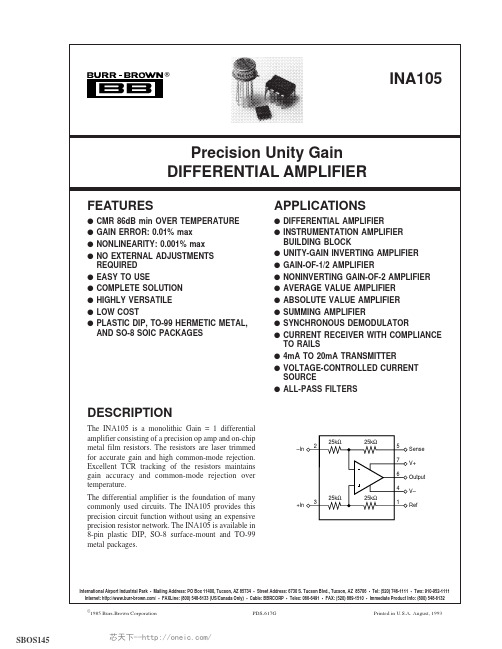
©1985 Burr-Brown Corporation PDS-617G Printed in U.S.A. August, 1993Precision Unity Gain DIFFERENTIAL AMPLIFIERCMR 86dB min OVER TEMPERATURE APPLICATIONSq DIFFERENTIAL AMPLIFIER q INSTRUMENTATION AMPLIFIER BUILDING BLOCK SBOS145芯天下--/SPECIFICATIONSELECTRICALAt +25°C, V CC = ±15V, unless otherwise noted.T Specification same as for INA105AM.NOTES: (1) Connected as difference amplifier (see Figure 4). (2) Nonlinearity is the maximum peak deviation from the best-fit straight line as a percent of full-scale peak-to-peak output. (3) 25kΩ resistors are ratio matched but have ±20% absolute value. (4) Maximum input voltage without protection is 10V more than either ±15V supply (±25V). Limit I IN to 1mA. (5) With zero source impedance (see “Maintaining CMR” section). (6) Referred to output in unity-gain difference configuration. Note that this circuit has a gain of 2 for the operational amplifier’s offset voltage and noise voltage. (7) Includes effects of amplifier’s input bias and offset currents. (8) Includes effects of amplifier’s input current noise and thermal noise contribution of resistor network.The information provided herein is believed to be reliable; however, BURR-BROWN assumes no responsibility for inaccuracies or omissions. BURR-BROWN assumes no responsibility for the use of this information, and all use of such information shall be entirely at the user’s own risk. Prices and specifications are subject to change without notice. No patent rights or licenses to any of the circuits described herein are implied or granted to any third party. BURR-BROWN does not authorize or warrant any BURR-BROWN product for use in life support devices and/or systems.®INA1052芯天下--/®INA1053PIN CONFIGURATIONSThis integrated circuit can be damaged by ESD. Burr-Brown recommends that all integrated circuits be handled with appropriate precautions. Failure to observe proper handling and installation procedures can cause damage.ESD damage can range from subtle performance degradation to complete device failure. Precision integrated circuits may be more susceptible to damage because very small parametric changes could cause the device not to meet its published specifications.ABSOLUTE MAXIMUM RATINGSSupply ................................................................................................±18V Input Voltage Range ............................................................................±V S Operating Temperature Range: M ..................................–55°C to +125°CP, U................................–40°C to +85°CStorage Temperature Range: M .....................................–65°C to +150°C P, U .................................–40°C to +125°C Lead Temperature (soldering, 10s) M, P .......................................+300°C Wave Soldering (3s, max) U ..........................................................+260°C Output Short Circuit to Common..............................................ContinuousPACKAGE DRAWING TEMPERATUREPRODUCT PACKAGE NUMBER (1)RANGE INA105AM TO-99 Metal 001–40°C to +85°C INA105BM TO-99 Metal 001–40°C to +85°C INA105KP 8-Pin Plastic DIP 006–40°C to +85°C INA105KU8-Pin SOIC182–40°C to +85°CNOTE: (1) For detailed drawing and dimension table, please see end of data sheet, or Appendix C of Burr-Brown IC Data Book.PACKAGE/ORDERING INFORMATION芯天下--/®INA1054SMALL SIGNAL RESPONSE(No Load)Time (µs)Ou t p u t V o l t a g e (m V )0510+50–50STEP RESPONSETime (µs)O u t p u t V o l t a g e (V )–10 t o +100481216SMALL SIGNAL RESPONSE (R LOAD = , C LOAD = 1000pF)Time (µs)O u t p u t V o lt a g e (m V )510+50–50Ω∞MAXIMUM V OUT vs I OUT(Negative Swing)–I OUT (mA)V O U T (V )–17.5–15–12.5–10–7.5–5–2.50–2–4–6–8–10–12CMR vs FREQUENCYFrequency (Hz)10C M R (d B )110100908070601001k10k 100kAM, KP, UBMMAXIMUM V OUT vs I OUT(Positive Swing)I OUT (mA)V O U T (V )17.51512.5107.552.5061218243036TYPICAL PERFORMANCE CURVESAt T A = 25°C, V S = ±15V, unless otherwise noted.芯天下--/®INA1055COMMON-MODE INPUT RANGE vs SUPPLY (Difference Amplifier Connected, V OUT = 0)Supply Voltage (V)±3I n p u t R a n g e (V )363024181260±6±9±12±15±18±21POWER SUPPLY REJECTIONvs FREQUENCYFrequency (Hz)1P S R R (d B )140120100806040101001k 10k 100kV–V+TYPICAL PERFORMANCE CURVES (CONT)At T A = 25°C, V S = ±15V, unless otherwise noted.APPLICATION INFORMATIONFigure 1 shows the basic connections required for operation of the INA105. Power supply bypass capacitors should be connected close to the device pins.The differential input signal is connected to pins 2 and 3 as shown. The source impedances connected to the inputs must be nearly equal to assure good common-mode rejection. A 5Ω mismatch in source impedance will degrade the com-mon-mode rejection of a typical device to approximately 80dB. If the source has a known mismatch in source imped-ance, an additional resistor in series with one input can be used to preserve good common-mode rejection.The output is referred to the output reference terminal (pin 1) which is normally grounded. A voltage applied to the Ref terminal will be summed with the output signal. This can be used to null offset voltage as shown in Figure 2. The source impedance of a signal applied to the Ref terminal should be less than 10Ω to maintain good common-mode rejection.Do not interchange pins 1 and 3 or pins 2 and 5, even though nominal resistor values are equal. These resistors are laser trimmed for precise resistor ratios to achieve accurate gain and highest CMR. Interchanging these pins would not pro-vide specified performance.FIGURE 1. Basic Power Supply and Signal Connections.芯天下--/®INA1056FIGURE 2. Offset Adjustment.FIGURE 3. Precision Difference Amplifier.FIGURE 4. Precision Instrumentation Amplifier.FIGURE 5. Current Receiver with Compliance to Rails.芯天下--/®INA1057FIGURE 6. Precision Unity-Gain Inverting Amplifier.FIGURE 7. ±10V Precision Voltage Reference.FIGURE 8. ±5V Precision Voltage Reference.FIGURE 10. Pseudoground Generator.FIGURE 11. Precision Average Value Amplifier.芯天下--/®INA1058FIGURE 15. Precision Bipolar Offsetting.FIGURE 12. Precision (G = 2) Amplifier.FIGURE 16. Precision Summing Amplifier with Gain.FIGURE 13. Precision Summing Amplifier.FIGURE 14. Precision Gain = 1/2 Amplifier.芯天下--/®INA1059FIGURE 17. Instrumentation Amplifier Guard Drive Generator.FIGURE 18. Precision Summing Instrumentation Amplifier.芯天下--/FIGURE 21. Isolating Current Source.®INA10510芯天下--/FIGURE 25. Precision Voltage-Controlled Current Source with Buffered Differential Inputs and Gain.FIGURE 27. Boosting Instrumentation Amplifier Common-Mode Range From ±5 to ±7.5V with 10V Full-Scale Output.FIGURE 28. Precision Absolute Value Buffer.FIGURE 29. Precision 4-20mA Current Transmitter.Addendum-Page 1PACKAGING INFORMATIONOrderable DeviceStatus(1)Package Type PackageDrawingPins Package QtyEco Plan(2)Lead/Ball FinishMSL Peak Temp (3)Samples (Requires Login)INA105AM NRND TO-99LMC 820Green (RoHS & no Sb/Br)AU N / A for Pkg Type Samples Not Available INA105BM NRND TO-99LMC 81Green (RoHS & no Sb/Br)AUN / A for Pkg TypeSamples Not Available INA105KP ACTIVE PDIP P 850Green (RoHS & no Sb/Br)CU NIPDAU N / A for Pkg Type Contact TI Distributor or Sales Office INA105KPG4ACTIVE PDIP P 850Green (RoHS & no Sb/Br)CU NIPDAU N / A for Pkg Type Contact TI Distributor or Sales Office INA105KU ACTIVE SOIC D 875Green (RoHS & no Sb/Br)CU NIPDAU Level-3-260C-168 HR Contact TI Distributor or Sales Office INA105KU/2K5ACTIVE SOIC D 82500Green (RoHS & no Sb/Br)CU NIPDAU Level-3-260C-168 HR Purchase Samples INA105KU/2K5E4ACTIVE SOIC D 82500Green (RoHS & no Sb/Br)CU NIPDAU Level-3-260C-168 HR Purchase Samples INA105KUE4ACTIVESOICD875Green (RoHS & no Sb/Br)CU NIPDAU Level-3-260C-168 HRContact TI Distributor or Sales Office(1)The marketing status values are defined as follows:ACTIVE: Product device recommended for new designs.LIFEBUY: TI has announced that the device will be discontinued, and a lifetime-buy period is in effect.NRND: Not recommended for new designs. Device is in production to support existing customers, but TI does not recommend using this part in a new design.PREVIEW: Device has been announced but is not in production. Samples may or may not be available.OBSOLETE: TI has discontinued the production of the device.(2)Eco Plan - The planned eco-friendly classification: Pb-Free (RoHS), Pb-Free (RoHS Exempt), or Green (RoHS & no Sb/Br) - please check /productcontent for the latest availability information and additional product content details.TBD: The Pb-Free/Green conversion plan has not been defined.Pb-Free (RoHS): TI's terms "Lead-Free" or "Pb-Free" mean semiconductor products that are compatible with the current RoHS requirements for all 6 substances, including the requirement that lead not exceed 0.1% by weight in homogeneous materials. Where designed to be soldered at high temperatures, TI Pb-Free products are suitable for use in specified lead-free processes.Pb-Free (RoHS Exempt): This component has a RoHS exemption for either 1) lead-based flip-chip solder bumps used between the die and package, or 2) lead-based die adhesive used between the die and leadframe. The component is otherwise considered Pb-Free (RoHS compatible) as defined above.Green (RoHS & no Sb/Br): TI defines "Green" to mean Pb-Free (RoHS compatible), and free of Bromine (Br) and Antimony (Sb) based flame retardants (Br or Sb do not exceed 0.1% by weight in homogeneous material)(3)MSL, Peak Temp. -- The Moisture Sensitivity Level rating according to the JEDEC industry standard classifications, and peak solder temperature.芯天下--/Important Information and Disclaimer:The information provided on this page represents TI's knowledge and belief as of the date that it is provided. TI bases its knowledge and belief on information provided by third parties, and makes no representation or warranty as to the accuracy of such information. Efforts are underway to better integrate information from third parties. TI has taken and continues to take reasonable steps to provide representative and accurate information but may not have conducted destructive testing or chemical analysis on incoming materials and chemicals. TI and TI suppliers consider certain information to be proprietary, and thus CAS numbers and other limited information may not be available for release.In no event shall TI's liability arising out of such information exceed the total purchase price of the TI part(s) at issue in this document sold by TI to Customer on an annual basis.Addendum-Page 2芯天下--/TAPE AND REEL INFORMATION*All dimensions are nominalDevicePackage Type Package Drawing Pins SPQReel Diameter (mm)Reel Width W1(mm)A0(mm)B0(mm)K0(mm)P1(mm)W (mm)Pin1Quadrant INA105KU/2K5SOICD82500330.012.46.45.22.18.012.0Q1*All dimensions are nominalDevice Package Type Package Drawing Pins SPQ Length(mm)Width(mm)Height(mm)INA105KU/2K5SOIC D8*******.0367.035.0IMPORTANT NOTICETexas Instruments Incorporated and its subsidiaries(TI)reserve the right to make corrections,enhancements,improvements and other changes to its semiconductor products and services per JESD46C and to discontinue any product or service per JESD48B.Buyers should obtain the latest relevant information before placing orders and should verify that such information is current and complete.All semiconductor products(also referred to herein as“components”)are sold subject to TI’s terms and conditions of sale supplied at the time of order acknowledgment.TI warrants performance of its components to the specifications applicable at the time of sale,in accordance with the warranty in TI’s terms and conditions of sale of semiconductor products.Testing and other quality control techniques are used to the extent TI deems necessary to support this warranty.Except where mandated by applicable law,testing of all parameters of each component is not necessarily performed.TI assumes no liability for applications assistance or the design of Buyers’products.Buyers are responsible for their products and applications using TI components.To minimize the risks associated with Buyers’products and applications,Buyers should provide adequate design and operating safeguards.TI does not warrant or represent that any license,either express or implied,is granted under any patent right,copyright,mask work right,or other intellectual property right relating to any combination,machine,or process in which TI components or services are rmation published by TI regarding third-party products or services does not constitute a license to use such products or services or a warranty or endorsement e of such information may require a license from a third party under the patents or other intellectual property of the third party,or a license from TI under the patents or other intellectual property of TI.Reproduction of significant portions of TI information in TI data books or data sheets is permissible only if reproduction is without alteration and is accompanied by all associated warranties,conditions,limitations,and notices.TI is not responsible or liable for such altered rmation of third parties may be subject to additional restrictions.Resale of TI components or services with statements different from or beyond the parameters stated by TI for that component or service voids all express and any implied warranties for the associated TI component or service and is an unfair and deceptive business practice. TI is not responsible or liable for any such statements.Buyer acknowledges and agrees that it is solely responsible for compliance with all legal,regulatory and safety-related requirements concerning its products,and any use of TI components in its applications,notwithstanding any applications-related information or support that may be provided by TI.Buyer represents and agrees that it has all the necessary expertise to create and implement safeguards which anticipate dangerous consequences of failures,monitor failures and their consequences,lessen the likelihood of failures that might cause harm and take appropriate remedial actions.Buyer will fully indemnify TI and its representatives against any damages arising out of the use of any TI components in safety-critical applications.In some cases,TI components may be promoted specifically to facilitate safety-related applications.With such components,TI’s goal is to help enable customers to design and create their own end-product solutions that meet applicable functional safety standards and requirements.Nonetheless,such components are subject to these terms.No TI components are authorized for use in FDA Class III(or similar life-critical medical equipment)unless authorized officers of the parties have executed a special agreement specifically governing such use.Only those TI components which TI has specifically designated as military grade or“enhanced plastic”are designed and intended for use in military/aerospace applications or environments.Buyer acknowledges and agrees that any military or aerospace use of TI components which have not been so designated is solely at the Buyer's risk,and that Buyer is solely responsible for compliance with all legal and regulatory requirements in connection with such use.TI has specifically designated certain components which meet ISO/TS16949requirements,mainly for automotive ponents which have not been so designated are neither designed nor intended for automotive use;and TI will not be responsible for any failure of such components to meet such requirements.Products ApplicationsAudio /audio Automotive and Transportation /automotiveAmplifiers Communications and Telecom /communicationsData Converters Computers and Peripherals /computersDLP®Products Consumer Electronics /consumer-appsDSP Energy and Lighting /energyClocks and Timers /clocks Industrial /industrialInterface Medical /medicalLogic Security /securityPower Mgmt Space,Avionics and Defense /space-avionics-defense Microcontrollers Video and Imaging /videoRFID OMAP Mobile Processors /omap TI E2E Community Wireless Connectivity /wirelessconnectivityMailing Address:Texas Instruments,Post Office Box655303,Dallas,Texas75265Copyright©2012,Texas Instruments Incorporated。
CS4205-KQ资料

PCM_DATA
Σ
LINE_OUT MONO_OUT
Preliminary Product Information
P.O. Box 17847, Austin, Texas 78760 (512) 445 7222 FAX: (512) 445 7581
This document contains information for a new product. Cirrus Logic reserves the right to modify this product without notice.
Copyright Cirrus Logic, Inc. 2001 (All Rights Reserved)
APR ‘01 DS489PP2 1
CS4205
TABLE OF CONTENTS
1. CHARACTERISTICS AND SPECIFICATIONS ..................................................................7 Analog Characteristics ........................................................................................................7 Absolute Maximum Ratings ................................................................................................8 Recommended Operating Conditions...........................
RCS-9200A微机五防系统技术和使用说明书介绍
奥马格 FPUD400系列扁平扁盘泵说明书

The OMEGA ® FPUD400 Series drumpumps can empty a wide variety of containers in various applications. The pump tube and motor are supplied separately in modular construction for maximum flexibility.Available motor types are 115 or 230 Vac powered, continuous duty, totally-enclosed, fan-cooled (TEFC) motors; and air driven motors.All Vac powered units include 3.6 m (12'), three-wire cord, built-in ON/OFF switch; and circuit breaker with manual reset. The FPUD411 includes a wall plug.The FPUD431 air motor has a ¹⁄₄" female NPT fitting for hooking up to a customer-supplied air hose, and includes a flow-regulating valve and muffler. Anoptional air lubricator/filter assembly is also available when your air source is not filtered and lubricated.When pumping flammable or combustible materials, or in explosive environments, use an air motor with a stainless steel tube and the FPUD34-SK static protection kit to avoid sparks produced by static electricity discharge.* For CE certified models, see order chart on next page.MediuM Viscosity druM PuMPsU P ump Tube and Motor Supplied Separately for Maximum Flexibility U C PVC, 316 SS or Sanitary Polished 316 SS Pump Tubes U T EFC or Air Driven Motors U F or Fluids up to2000 cps Viscosity and 1.8 Specific GravityThe FPUD4-SNT40 sanitary pump tube features a polished 316 SS tube and shaft, a graphite-filled seal, and pure PTFE internals. It has an ACME sanitary nut connection so the tube can be easily removed for cleaning.FPUD4 Series pump tubes are rated up to 65°C (150°F) (SS and sanitary tubes), or 82°C (180°F) (CPVC tubes), 2,000 cps viscosity (2000 cps air motor; 400 cps electric motor) and 1.8 specificgravity. All tube assemblies have graphite-PTFE seals with PTFE internals, and feature 25 mm (1") ID hose connection on the outlet.Refer to performance graphs for flow rate vs. discharge head data.FPUD4 Pump TubesFPUD400Pump MotorsShown smaller than actual sIze.FPUD411, 115 Vac motorFMXD11-AM,air motor.LComes complete with operator’s manual. AC pump motors include integral power cords.Power cords for 115 Vac models include grounded wall plugs.Ordering Examples: FPUD411, 115 Vac motor and, FPUD4-S40 316 SS pump tube.FPUD431, 80 psi air motor, FPUD34-SK, anti-static kit and FPUD4-C40 CPVC 15⁄8" pump tube.FPUD34-SK,FPUD4-SNT40, sanitary pump tube FPUD4-C40, CPVC pumptube FPUD4-S40,316 SS pump tubeAll shown smaller than actual size.FPUD4-PSFPUD4-SSFPUD4-SDA-S。
гомдустру roduction EFPAU TEST NO说明书
感谢您购买 产品!请仔细阅读本手册,它将帮助你妥善设置并运行您的系统,使其发挥卓越的性能。
并保留这些说明以供日后参照。
警告:为了降低火灾与电击的风险,请不要将产品暴露在雨中或潮湿环境中。
警告:为了降低电击的风险,非专业人士请勿擅自拆卸该系统。
仅供专业人士操作。
等边三角形中的闪电标记,用以警示用户该部件为非绝缘体,系统内部存在着电压危险,电压。
可能足以引起触电。
可能足以引起触电如系统标有带惊叹号的等边三角形,则是为提示用户严格遵守本用户指南中的操作与维护规定。
注意:请勿对系统或附件作擅自的改装。
未经授权擅自改装将造成安全隐患。
警告:燃不得将明火源(如点的蜡烛)放在器材上面。
1. 请先阅读本说明。
2. 保留这些说明以供日后参照。
3. 注意所有警告信息。
4. 遵守各项操作指示。
5. 不要在雨水中或潮湿环境中使用本产品。
6. 不要将产品靠近热源安装,例如暖气管、加热器、火炉或其它能产生热量的装置(包括功放机 )。
7. 不要破坏极性或接地插头的安全性设置。
如果提供的插头不能插入插座,则应当请专业人员更换插座。
8. 保护好电源线和信号线,不要在上面踩踏或拧在一起(尤其是插头插座及穿出机体以外的部分 )。
9. 使用厂商规定及符合当地安全标准的附件。
10.雷电或长时间不使用时请断电以防止损坏产品。
12. 不要让物体或液体落入产品内——它们可能引起火灾或触电。
13. 请注意产品外罩上的相关安全标志。
. 仅与厂商指定或与电器一同售出的推车、架子、三脚架、支架或桌子一起使用。
推动小车/电器时,应谨防翻倒。
11注意事项产品的安装调试须由专业人士操作。
在使用非本厂规定的吊装件时,要保证结构的强度并符合当地的安全规范。
警告:1扬声器及扬声器系统的产品有限保修期为自正式购买日起的3年。
由于用户不合理的应用而导致音圈烧毁或纸盆损坏等故障,不包含于产品保修项目。
产品吊附件(包括音箱装配五金件和吊挂配件)的有限保修期为自正式购买日起的1年。
- 1、下载文档前请自行甄别文档内容的完整性,平台不提供额外的编辑、内容补充、找答案等附加服务。
- 2、"仅部分预览"的文档,不可在线预览部分如存在完整性等问题,可反馈申请退款(可完整预览的文档不适用该条件!)。
- 3、如文档侵犯您的权益,请联系客服反馈,我们会尽快为您处理(人工客服工作时间:9:00-18:30)。
Broadband TelCom Power, Inc.
BTCPower BTCPower
TM
Redefining “Current” Limits In Power Conversion
BAO40 Series
40W Open Frame AC-DC Power Modules
• Universal Input 90-264 Vac • PCB Mountable • Efficiency to 85%
• Industry Standard Pin Out • 100 % full load burn-in test
• ISO-9001 certified manufacturer
•
Short circuit / overload / over voltage protection
• Approvals: UL / TUV / CE
Specifications
Input voltage range………………………………………………………………..90-264 Vac Input frequency………….…………………………………………………………47 – 63 Hz
Inrush current………………………………………………………………………Cold start, 25A / 155Vac, 50A / 230Vac Output voltage….………………………………………………………………….Refer to below table Initial Accuracy …………………………………………………………………….±1.0% max. Temperature Coefficient ………………………………………………………….±0.05% / ºC
Ripple & Noise, 20Mhz BW ………………………………………….…………. .50mVp-p, max @ 3.3/5Vo; 1%p-p,max @ other output voltage modules Hold-up time ¹ ……………………………………………………………………..8ms typ. Short circuit protection……………...………………………………………….…Continuous Line regulation ² .………………………………………………………………….±0.05% max. Load regulation ³ ……………………………………………………………….…±1.0% max.
Efficiency ………..…..………………………………………………………….…Refer to below table Isolation Voltage (Input/Output) …………………………………………….. .4242 Vac Operating temp. range …………………………………………………………..0 ºC – 50 ºC Storage temp. range ………………………..…………………………………...-40 ºC – +100 ºC Cooling…………………………………………………………………………..…Free air convection
Part No
Output
Tolerance
Ripple
Efficiency
BAO40-UAC-3.3 3.3V, 6A +/ - 1 % 50 mV 74% BAO40- UAC-5 5V, 6A +/ - 1 % 50 mV 78% BAO40- UAC-9 9V, 4.45A +/ - 1 % 90 mV 82% BAO40- UAC-12 12V, 3.34A +/ - 1 % 120 mV 84% BAO40- UAC-15 15V, 2.67A +/ - 1 % 150 mV 85% BAO40- UAC-24 24V, 1.67A +/ - 1 % 240 mV 86% BAO40- UAC-30 30V, 1.33A +/ - 1 % 300 mV 86% BAO40- UAC-36 36V, 1.11A +/ - 1 % 360 mV 87% BAO40- UAC-48
48V, 0.834A
+/ - 1 %
480 mV
88%
Note: The output voltage cab be 0.1V interval changed .
元器件交易网
BTCPower BTCPower
T M
Broadband TelCom Power, Inc. – 1719 S. Grand Avenue, Santa Ana, CA 92705 U.S.A. Pg. 2.
Tel.: 714-259-4888 • Fax: 714-259-0840 • • Email: sales@ AC/DC BAO40 PS Ver1 8-7-03
Note:
1. Measured at Vin = 115 Vac, Full load
2. Measured from high line to low line
3.
Measured from full load to 10% load
4. BAO40 input connector mates with Molex housing 09-50-3031 and Molex 2878 series crimp terminal.
5.
BAO40 output connector mates with Molex housing 09-50-3041 and Molex 2878 series crimp terminal.
MECHANICAL DRAWING
元器件交易网。