The Class-D Amplifier(课程教材)
d类功放转电流

d类功放转电流D类功放转电流的原理及应用引言:D类功放(Class D amplifier)是一种高效率的功率放大器,其工作原理是通过将音频信号转换为脉冲宽度调制(PWM)信号,然后经过滤波器得到模拟音频信号输出。
本文将介绍D类功放的工作原理,并探讨其在音响领域的应用。
一、D类功放的工作原理D类功放的核心是脉冲宽度调制技术。
当输入音频信号为正弦波时,D类功放将其转化为一系列的脉冲信号,脉冲的宽度随着音频信号的幅度变化而调整。
这些脉冲信号经过一个高频开关管(MOSFET)进行放大,然后由低通滤波器进行滤波,最终得到模拟音频信号输出。
D类功放的工作过程可以分为两个阶段:脉冲宽度调制和功率放大。
脉冲宽度调制阶段通过比较器和误差放大器将音频信号转化为PWM 信号,PWM信号的频率通常在几十千赫茨到几百千赫茨之间。
功率放大阶段则通过高频开关管对PWM信号进行放大,将其转化为模拟音频信号输出。
二、D类功放的优势相比传统的A类和AB类功放,D类功放具有以下优势:1. 高效率:由于D类功放采用了脉冲宽度调制技术,其功率转换效率通常可达到90%以上,远高于传统功放的效率。
2. 小尺寸:D类功放由于功率转换效率高,不需要大型散热器,因此体积更小,更适合集成在各种便携设备中。
3. 低热量:传统功放在工作时会产生大量的热量,而D类功放由于高效率的原因,热量较少,不易造成设备过热。
4. 低失真:D类功放的PWM信号经过滤波器后,可以得到较为纯净的模拟音频信号,音质更好,失真更低。
三、D类功放在音响领域的应用D类功放由于其高效率和小尺寸的特点,在音响领域得到了广泛的应用。
以下是几个常见的应用场景:1. 车载音响:由于车载空间有限,需要小尺寸的功放设备,D类功放能够满足这一需求,并且其高效率可以减少对汽车电池的负担。
2. 便携式音箱:便携式音箱通常需要长时间的续航能力,D类功放的高效率可以延长电池的使用时间,同时小尺寸也方便携带。
d类功放原理
d类功放原理D类功放原理。
D类功放(Class-D Amplifier)是一种高效率的功率放大器,它利用数字调制技术将音频信号转换成脉冲宽度调制(PWM)信号,然后通过功率开关器件进行放大。
与传统的A类、B类功放相比,D类功放具有更高的效率和更小的体积,因此在音响设备、汽车音响和无线通信等领域得到了广泛的应用。
D类功放的工作原理可以简单地分为两个部分,信号调制和功率放大。
首先,音频信号经过模数转换器(ADC)转换成数字信号,然后经过数字信号处理器(DSP)进行数字调制,将其转换成PWM信号。
PWM信号的脉冲宽度与音频信号的幅度成正比,频率与音频信号的频率相同。
这样就实现了对音频信号的数字化处理。
接下来,PWM信号通过功率开关器件(如MOSFET、IGBT)控制输出级的功率开关,将电源电压施加在负载上,从而实现对音频信号的功率放大。
在输出级,PWM信号经过滤波器进行滤波处理,去除高频成分,得到原始的音频信号。
最后,经过放大器输出到扬声器或其他负载上。
D类功放相比传统的A类、B类功放具有很多优点。
首先,D类功放的效率非常高,通常可以达到90%以上,而A类、B类功放的效率只有50%左右。
这意味着D类功放在同样输出功率下,可以减少很多功率损耗,从而减小散热器的尺寸和成本。
其次,D类功放的失真度较低,因为功率开关器件的开关速度非常快,可以更准确地跟随音频信号的变化,减少失真。
此外,D类功放的体积小、重量轻,适合于便携式音响设备和汽车音响系统的应用。
然而,D类功放也存在一些缺点。
首先,由于功率开关器件的开关频率较高,会产生一定的高频谐波,需要进行滤波处理,增加了设计的复杂度。
其次,功率开关器件的开关损耗会产生一定的电磁干扰,需要进行屏蔽和抑制。
另外,D类功放对电源的要求较高,需要较为稳定的直流电源,以保证输出的音频质量。
总的来说,D类功放作为一种高效率、高保真度的功率放大器,已经成为现代音响设备和汽车音响系统的主流选择。
D题:带啸叫检测与抑制的音频功率放大器--谭文王韬方向宏
D题:带啸叫检测与抑制的音频功率放大器--谭文王韬方向宏D题:带啸叫检测与抑制的音频功率放大器--谭文王韬方向宏2014年TI杯大学生电子设计竞赛D题:带啸叫检测与抑制的音频功率放大器(本科)王韬谭文方向宏2014.8.15啸叫抑制系统报告一、摘要本文基于TI的D类功放TPA3112D1,以前置全向麦克风采集语音信号,通过信号提取,滤波,功率放大等处理,通过8欧姆5W喇叭输出声音,并通过啸叫声频率检测电路反馈,由高阶程控陷波器LTC1068-25,完成啸叫检测、啸叫抑制以及功率计算等功能,系统效率较高。
关键字:D类功放啸叫声频率检测程控陷波器Based on TI's Class-D amplifier TPA3112D1, in front the whole collection to the microphone voice signal by signal extraction, filtering, power amplification and other processing, by 8 ohm 5W speaker output sound and frequency detection circuit by howling feedback from higher-order programmable notch filter LTC1068-25,complete howling detection, howling suppression and powercalculation functions, higher system efficiency.二、题目描述2.1 任务基于TI的功率放大器芯片TPA3112D1,设计并制作一个带啸叫检测与抑制功能的音频放大器,完成对台式麦克风音频信号进行放大,通过功率放大电路送喇叭输出。
电路示意图如图1所示。
2(要求(1)设计并制作图1中所示的“拾音电路”和“功率放大电路”,构成一个基本的音频功率放大器。
各类音频放大电路

D类音频功率放大器(Class D Audio Power Amplifier)近二十年来电子学课本上所讨论的放大器偏压(Bias)分类不外乎A类、B类、C类等放大电路,而讨论音频功率放大器仅强调A类、B类、AB类而却把D类放大器给忘掉了,事实上D类放大器早在1958年已被提出(注一),甚至还有E 类、F类、G类、H类及S类等(注二),只是这些类型的电路与D类很接近,运用机会低,所以也就很少被提及。
音频功率放大器最大目的在提供喇叭得到最大功率输出,而卫衍生与电源所供给功率不对等的关系,即所谓功率放大器的效率(输出功率与输入功率之比)如表一所示:表一各類功率放大器的效率比随着轻、薄、短、小手持电子装置的发展,诸如手机、MP3、PDA、IPOD 及LCD TV…数位家庭等,寻求一个省电的高效率音频功率放大器是必然的。
因此最近几年音频功率放大器由AB类功率放大器转以D类功率放大器为主流。
如图1所示(注三),在实际应用上D类放大效率可达90%以上远超过效率50%的AB类放大。
所以D类放大的晶体管散热可大大的缩小,很适合应用于小型化的电子产品。
圖 1 D類及AB 類效率比A类放大器(又称甲类放大器)的特点是不论是否输入信号,其输出电路恒有电流流通,而且这种放大器通常是在特性曲线的线性范围内操作,如图2所示,以求放大后的信号不失真。
所以它的优点,是失真度小,信号越小传真度越高,最大的缺点是“功率效益”(Power Efficiency)低,最大只有25%,不输入信号时丝毫不降低消耗功率,极不适合做功率放大。
但因其高传真度,部分高级音响器材仍采用A类放大器。
图1图2(a)、(b)皆属A类放大器,设计时让V CE=1/2V CC,以求最大不失真范围。
注意到V i 不输入时仍有0.5V CC/R L的电流流过晶体管,所以晶体管需要良好的散热环境。
由于“共集极”组态(图2(a) Common Collector组态又称“射极跟随器”)转移特性曲线较“共射极”组态(图2(b) Common Emitter组态)有较佳的线性度(亦即失真较低)及较低的输出组抗,因此,同属于A类放大器,射级随耦器却较常被当成输出级使用(“共射级”组态较常被当成“驱动级”使用)。
Class-D功放详解
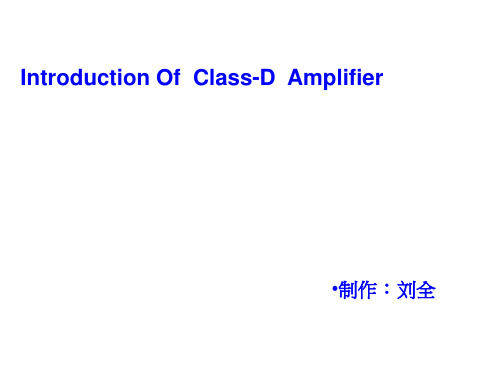
图2 原始信号和PWM输出信号以及经过低 通滤波器以后的信号频谱
雖然Class-D Amplifier 的工 作原理都是依靠PWM調製技術, 但在具體採樣方式和時序上,各 個廠商之間卻各不相同,以TI & PAM為例:
右圖為TI廠商型號:TPA3110D2 全橋輸出的波形。黃色曲綫和藍 色曲綫分別為負載兩端對地的波 形,紅色曲綫為黃色曲綫與藍色 曲綫做減法運算得到的波形即負 載的輸出波形。
最简单的PWM就是一个比较器,它的一端输入原始要放大的信号,另一端就 输入一个高频三角波。在这个比较器的输出就是一个脉宽被调制的矩形波。 这个矩形波就直接加到一对互补晶体管进行放大 。
NOTE:采用负反馈回路可降低失真,最简单的方式:直接从输出端经过RF反馈到输入端。
三角波可以采用如右图的方 式来产生。比较器输出的电 压为+V1和-V1。当输出电 压为-V1时,三角波以 m=V1/R6C4的斜率增长。假定 三角波的峰值幅度为从+VTP 到-VTP。再假定三角波的周 期为T=1/fT。那么较器在 其非倒相输入端的电压达到0 时,切换其状态。这发生于 V1/R8=VTP/R7。所以,三角 波的频率就等于
• Amplifiers that provide features like • Volume control • Speaker and headphone drive • I2C interface • Bass boost • Small package options
图5. D类放大器的结构图
OUTLINE
Class-D Audio Amplifier 的工作原理和结构特点
The Principle Of Class-D Amplifier
Class-D功放详解

• 图8.半桥式和全桥式结构比较
Compare Class-D Amplifier With Class AB
Audio amplifier basic configuration
Class-AB vs. Class-D
Class-AB amplifiers use the same push-pull architecture as class-B, but active devices are biased on with a small quiescent current when Vin = 0.
• NOTE:为了不失真地放大最高频率分量为 20KHz的音频信号,三角波的重复频率最好在十倍 音频的最高频率分量,也就是200KHz以上
右圖表明了一个1KHz的正 弦波音频信号,经过三角波 采样后的输出频谱,其中包 含有很多高频分量。在 PWM的输出后面加上一个 低通滤波器,就可以滤去矩 形波的高频分量。
advantage: excellent linearity
disadvantage: poor efficiency
Q4
Q3
Q5 Vin
PVDD
Q1
C1 Q2
Rload
Class-D amplifiers modulates the audio signal in to a high frequency PWM signal that drives the speaker(s).
fT=R8/4R6R7C4, VTP=V1R7/R8
图6. 三角波发生器
NOTE:积分电路的输出电压与输入 电压的积分成反比关系,所以阶跃信 号输入积分电路后会输出一个比例函 数的波形。
Class-D功放详解

Class D Vin
AP
LPF
AP
圖12 Test of Class-D and ClassAB
D类放大器的失真
Major Cause of Imperfection
Feedback Integrator
Switch nonidealities
Finite Ron Body diode Recovery (EMI)
最简单的PWM就是一个比较器,它的一端输入原始要放大的信号,另一端 就输入一个高频三角波。在这个比较器的输出就是一个脉宽被调制的矩形 波。这个矩形波就直接加到一对互补晶体管进行放大 。
NOTE:采用负反馈回路可降低失真,最简单的方式:直接从输出端经过RF反馈到输入端。
三角波可以采用如右图的方
式来产生。比较器输出的电 压为+V1和-V1。当输出电 压为-V1时,三角波以 m=V1/R6C4的斜率增长。假 定三角波的峰值幅度为从+ VTP到-VTP。再假定三角波 的周期为T=1/fT。那么2VTP =mT/2=V1/2fTR6C4。比较 器在其非倒相输入端的电压 达到0时,切换其状态。这发 生于V1/R8=VTP/R7。所以, 三角波的频率就等于
NOTE:死区时间会严重影响失真,时长 几十纳秒就可能导致THD达到1%以上。
图13 THD and Dead time
Power Supply Pumping
另一个导致THD增大的原因是总 线充电,可以在半桥拓扑向负载提 供低频的输出信号时观察到如右。 这主要是由于D类Amplifier的增益 与Vbus直接成比例关系,Vbus波 动造成输出失真。由于D类 Amplifier的开关时双向的,当大 量LPF电感储存的能量回流至电源 时,电源无法吸收从而导致Vbus 上升产生波动。
ClassD功放详解
Others:
THD+N (ex.0.01%, 80dBFs, A weighting Filter) Cross-Talk For Stereo
NOTE:死区时间会严重影响失真,时长 几十纳秒就可能导致THD达到1%以上。
图13 THD and Dead time
Power Supply Pumping
另一个导致THD增大的原因是总 线充电,可以在半桥拓扑向负载提 供低频的输出信号时观察到如右。 这主要是由于D类Amplifier的增益 与Vbus直接成比例关系,Vbus波 动造成输出失真。由于D类 Amplifier的开关时双向的,当大 量LPF电感储存的能量回流至电源 时,电源无法吸收从而导致Vbus 上升产生波动。
图7. 全橋式桥式输出的D类放大器
• 图8.半桥式和全桥式结构比较
Compare Class-D Amplifier With Class AB
Audio amplifier basic configuration
Class-AB vs. Class-D
Class-AB amplifiers use the same push-pull architecture as class-B, but active devices are biased on with a small quiescent current when Vin = 0.
完全工作于开关状态,損耗很小
只要考虑在导通时的损耗。假定
负载电阻为RL,晶体管导通时的 内阻为Ron,則效率為:
•
E=RL/(2Ron + RL)
• 除外,偏置电流、输入电容充 电、和切换电流都会降低效率,
右图为D类放大器和AB类放大器 在不同的输出功率时的效率 。
- 1、下载文档前请自行甄别文档内容的完整性,平台不提供额外的编辑、内容补充、找答案等附加服务。
- 2、"仅部分预览"的文档,不可在线预览部分如存在完整性等问题,可反馈申请退款(可完整预览的文档不适用该条件!)。
- 3、如文档侵犯您的权益,请联系客服反馈,我们会尽快为您处理(人工客服工作时间:9:00-18:30)。
The Class-D Amplifier(From the book Introduction to Electroacoustics and Audio Amplifier Design,Second Edition-Revised Printing,by W.Marshall Leach,Jr.,published by Kendall/Hunt, c°2001.)A class-D amplifier is one in which the output transistors are operated as switches.When a transistor is off,the current through it is zero.When it is on,the voltage across it is small,ideally zero.In each case,the power dissipation is very low.This increases the efficiency,thus requiring less power from the power supply and smaller heat sinks for the amplifier.These are important advantages in portable battery-powered equipment.The“D”in class-D is sometimes said to stand for“digital.”This is not correct because the operation of the class-D amplifier is based on analog principles.There is no digital coding of the signal.Before the advent of the class-D amplifier,the standard classes were class-A,class-AB,class-B,and class-C.The“D”is simply the next letter in the alphabet after“C.”Indeed,the earliest work on class-D amplifiers involved vacuum tubes and can be traced to the early1950s.Fig.1shows the basic simplified circuit of a class-D amplifier.We assume a bipolar power supply so that V−=−V+.The amplifier consists of a comparator driving two MOSFET transistors which operate as switches.The comparator has two inputs.One is a triangle wave,the other is the audio signal.The frequency of the triangle wave must be much higher than that of the audio input.The voltage output of the comparator can be writtenv C=−V1for v S>v T v C=+V1for v S<v T(1)This voltage is applied to the input of a complementary common-source MOSFET output stage. Each transistor operates as a switch.For v C=−V1,M1is on and M2is off.If the voltage drop across M1is negligible,then v0O=V+.Similarly,for v C=+V1,M2is on,M1is off,and v0O=V−. In practice,there is a small voltage drop across the on MOSFET switch so that the peak output voltage is less than the power supply voltage.For the case v S=0,v0O is a symmetrical square wave.The low-passfilter consisting of L1and C1passes the average value of the square wave to the loudspeaker,which is zero.Thus v O=0for v S=0.The network consisting of R1and C2compensates for the inductive impedance of the loudspeaker voice coil so that thefilter sees a resistive load at high frequencies.Figure1:Basic class-D amplifier.Fig.2shows the circuit waveforms for the case where v S is a sine wave.For purposes of illustration,the sine wave frequency is f S=1kHz and the triangle wave frequency is f T=20kHz. The sine wave amplitude is0.75V T P.For v S>0,the duty cycle of the square wave changes so that v0O spends more time at its positive level than at its negative level.This causes v0O to have a positive average value.Similarly,for v S<0,v0O has a negative average value.The waveform for v0Ois said to be pulse-width-modulated.The passive filter consisting of L 1and C 1passes the averageor low-frequency value of v 0O to the loudspeaker load and rejects the higher-frequency harmonics ofthe switching waveform.Figure 2:Ampli fier voltage waveforms.The e ffective gain of the ampli fier can be determined by applying a dc voltage at the input andcalculating the ratio of h v 0O i to v S ,where h v 0O i denotes the low-frequency time average of v 0O .If v S is increased,h v 0O i increases linearly until it reaches the level V OP ,which corresponds to the positiveclipping voltage at the output.This occurs when v S =V T P .It follows that the e ffective gain k is given by k =h v 0O i v S =V OP V T P(2)Fig.3shows the waveforms of the output voltage v O for two values of the cuto fffrequency of the LC filter.The transfer function of the filter isV o V 0o =1(s/ωc )2+(1/Q c )(s/ωc )+1(3)where ωc =2πf c =1/√L 1C 1is the resonance frequency and Q c =1/(ωc R L C 1)is the qualityfactor.The load resistance R L is the e ffective high-frequency resistance of the loudspeaker voice coil in parallel with the matching network consisting of R 1and C 2.The quality factor is Q c =1/√2for the waveforms in Fig.3so that the gain is down by 3dB at ωc .The signal frequency is f S =1kHz.The filter resonance frequency for the v O 1waveform is f c =1kHz.For the v O 2waveform,it is f c =8kHz.The harmonics of the pulse-width-modulated signal are clearly visible on the v O 2waveform.For minimum distortion,the frequency of the triangle wave should be as high as possible compared to the cuto fffrequency of the filter.Because the filter resonance frequency corresponds to the signal frequency for the v O 1waveform in Fig.3,the phase lag is 90o .The phase lag for the v O 2waveform is less because the resonance frequency is greater than the signal frequency.A higher-order filter can be used to more e ffectively remove the high-frequency switching harmonics.For example,a third-order LC filter or a fourth-order filter consisting of the cascade of two second-order LC filters could be used.Fig.4shows the spectrum of the v 0O waveform.It contains a fundamental at f S .Above f S ,the signi ficant switching harmonics are at f T ,f T ±2f S ,2f T ±f S ,2f T ±3f S ,etc.The lowest of these is at the frequency f T −2f S .The triangle wave frequency must be chosen high enough soFigure3:Output voltage waveforms for two different LCfilter cutofffrequencies.that the lowest significant harmonic is well above the highest signal frequency of interest.Thus we have the requirement f T−2f SÀf S or f TÀ3f S.To minimize ripple on the output,the cutofffrequency of the LCfilter should be much lower than f T.For example,in a wideband amplifier with a maximum signal frequency of20kHz,the switching frequency should ideally be600kHz or greater.Because of limitations imposed by a high switching frequency,a more practical value might be300kHz.The−3dB frequency of the LCfilter should be much lower than the switching frequency.For example,it might be30kHz for a300kHz switching frequency.Note that the amplitude of the harmonic at f T is larger than that of the signal.At the signal clipping level,the signal harmonic becomes1.5times as large as the harmonic at f T.Figure4:Unfiltered spectrum of the output voltage.Negative feedback can be used around the basic amplifier circuit to improve its performance. Fig.5shows such a circuit.The input op amp acts as an integrator to set the bandwidth.For a sinusoidal input signal with a frequency much lower than the switching frequency,the effective transfer function for the circuit and its pole frequency are given byV0o V s =−R FR211+s/ω0ω0=2πf0=kR F C F(4)The pole frequency must be greater than the highest frequency to amplified but lower than the switching frequency.Because the integrator has a very high gain at dc,it acts to minimize dc offsets at the output.For a wide band amplifier,a typical value of f0might be60kHz.Class-D amplifiers are often operated in a bridged configuration to increase the output power without increasing the power supply voltages.A bridged output stage is shown in Fig.6.A typical input circuit is shown in Fig.7.The feedback voltage v F is proportional to the difference voltageFigure5:Amplifier with negative feedback.v0O1−v0O2.The bridge circuit is often designed with V−=0and a dc offset at each output of V+/2 V,thus eliminating the need for a bipolar power supply.Figure6:Bridged output stage.Figure7:Input stage to the bridged amplifier with feedback.In the circuit of Fig.7,a diffamp is used to subtract v0O2from v0O1.The capacitors labeled C3 act as low-passfilters to limit the rise time of the signals applied to the op amp to prevent slewing. The transfer function for the diffamp and its pole frequency are given byV fV0o1−V0o2=R5R3+R411+s/ω1ω1=2πf1=1(R3k R4)C3(5)The overall transfer function for the amplifier is given byV0o1−V0o2V s =−R FR2R3+R4R51+s/ω1s/ω1ω2+s/ω2+1=−R FR2R3+R4R51+s/ω1(s/ω0)2+(1/Q0)(s/ω0)+1(6)whereω2,ω0,and Q0are given byω2=2πf2=R5R3+R4kR F C Fω0=2πf0=√ω1ω2Q0=rω2ω1(7)The amplifier should exhibit good stability for Q0≤1.Thus we have the conditionω1≥ω2. However,the simple model used here neglects higher order poles.Because the existence of such poles degrades stability,a conservative approach might be to design for Q0≤0.5so that the poles in Eq.(6)are real.This requiresω1≥4ω2.For example,in a wideband amplifier utilizing a switching frequency of300kHz,f1might be chosen to be equal to the switching frequency and f2 might be chosen to be75kHz.An example triangle wave generator circuit is shown in Fig.8.The circuit consists of an inte-grator driving a comparator that is connected as a Schmitt trigger.The output of the comparator drives the input to the integrator.Let the comparator output voltages be+V1and−V1.When the voltage is at the−V1level,the triangle wave output rises with the slope m=V1/R6C4.Let the peak values of the triangle wave be+V T P and−V T P.It follows that2V T P=mT/2=V1/2f T R6C4, where T=1/f T is the period of the triangle wave.The comparator switches states when the volt-age at its non-inverting input goes through zero.This occurs when V1/R8=V T P/R7.Solution forf T and V T P yieldsf T=R84R6R7C4V T P=R7R8V1(8)Figure8:Triangle wave generator.A problem called“shoot through”can reduce the efficiency of class-D amplifiers and lead to potential failure of the output devices.This occurs during the transition when one device is being cut offand another is being cut on.During the transition,both devices are on and a large current pulse canflow through the two.This can be eliminated by driving the gates of the MOSFETs with asymmetrical square waves such that one device is cut offbefore the other is cut on.One way of achieving this in the circuit of Figs.1and5is to use two comparators,one for each MOSFET.A positive dc offset is added to the triangle wave input to the comparator which drives M1and a negative dc offset is added to the triangle wave input to the comparator which drives M2.This effectively adds crossover distortion to the v0O output waveform,but the frequency components are above the switching frequency,thus outside the audio band.The high switching frequency used in class-D amplifiers is a potential source of rf interference with other electronic equipment.The amplifiers must be properly shielded and grounded to prevent radiation of the switching harmonics.In addition,low-passfilters must be used on all input and output leads,including the power supply leads.A variation of the class-D amplifier is called afilterless class-D amplifier.In the absence of an input signal,its output signal is zero rather than a symmetrical square wave.This eliminates the need of a low-passfilter to prevent application of the square wave to the loudspeaker.When the input voltage goes positive,the output voltage is a train of pulse width modulated pulses which switch between0and+V OP.When the input voltage goes negative,the output voltage is a train of pulse width modulated pulses which switch between0and−V OP.This is illustrated in Fig.9.The loudspeaker responds to the average value of the signal,which is the audio signal.Because there is nofilter,rf interference problems require the amplifier to be mounted as close to the loudspeaker as possible.The spectrum of the output signal is shown in Fig.10.One problem with thefilterless class-D amplifier is crossover distortion.To eliminate this,the FET control logic must be designed so that the amplifier puts out very narrow alternating positive and negative pulses in the absence of an input signal.In effect,this biases the amplifier in the class-AB mode.Figure9:Amplifier voltage waveforms.Figure10:Spectrum of the output voltage v0O.。
