4端口FXS语音接口模块产品手册
语音网关-FXO与-FXS工作原理
语音网关FXO与FXS工作原理FXO与FXS区别在VOIP网络中,语音网关是PSTN电话向VOIP电话过渡的产物,因此语音网关在VOIP网络环境中扮演一个重要的角色。
那么提到语音网关我们就不得不提到FXO和FXS两个关键字,这两个概念比较难理解,下面我们来通过了解语音网关的工作原理,组成结构以及应该用环境来了FXO和FXS 的区别。
一,语音网关工作原理就 PSTN 上的传统电话连接而言,电话局端交换提供电源与电话振铃。
电话本身提供塞尖(tip) /振铃电路,以请求服务或应答来自 PSTN 的呼叫。
对于通过因特网拨打的呼叫,FXS 电路将模拟电话局端交换的功能。
语音网关虚拟为交换机,为电话提供电源并进行振铃,并检测环路电流。
而在另一方面,FXO 电路则模拟电话功能,提供环路关闭功能并检测来话振铃。
二,FXS,FXO的组成部分我们了解了语音网关的工作原理之后,下面介绍一下FXS,FXO的组成部分:FXS 电路包括两部分:CODEC 与 SLIC(用户线路接口电路)。
CODEC由 ADC与 DAC构成。
ADC 将来自模拟电话的模拟信号转换为可通过VoIP网络传输的数字信号。
DAC将数字信号转换为模拟电平,以驱动模拟电话。
为了实现 4kHz的音频带宽, ADC与DAC的采样速率通常约为8kHz 。
SLIC 器件模拟PSTN电压电平。
它必须检测电话挂机还是摘机,并生成高达120V的振铃电压。
FXO电路包括CODEC与数据存取装置(DAA)。
CODEC与 FXS的功能相同,将模拟语音转换为数字信号,随后再转换回来。
DAA模拟(POTS)电话功能,其重要作用是去除高电压直流偏置,将PSTN 环路关闭,从而仅传送来自PSTN的模拟交流信号。
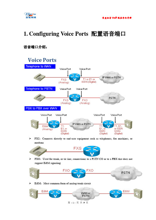
三,举例说明上面的说明或许比较复杂,下面我们通过一个例子可以很清楚的理解FXO和FXS网关在VOIP 环境中所扮演的角色FXS( Foreign eXchange Station)是用来连接传统电话机使用的,普通话机连接上语音网关的FXS口之后,他能够为话机提供电流与拨号音。
FXO中继模块说明

4.1 结构尺寸(Package Outline)
第 9页,共 10页
产品规格书
产品型号:TY4O-3/5A REV2.0 —————————————————————————————————————————
图 5 双列直插外形尺寸图(内孔径 35mil) 说明:1,模块使用的插针为定制型的 2.54mm 间距的方形插针。
2,推荐工作条件 (Recommended Operating Conditions)
参数(parameter)
符号(symbol)
数字电压(DC supply)
VDD
工作温度(Operating Temperature Range)
Ta
存储温度(Storage Temperature Range)
电话线对 3 的 T 线,也即 A 线 电话线对 3 的 R 线,也即 B 线 电话线对 4 的 T 线,也即 A 线 电话线对 4 的 R 线,也即 B 线
中断输出,OD 门,低电平有效, 需外接上拉电阻 SPI 总线片选信号,低电平有效,对应 1、2 路 SPI 总线片选信号,低电平有效,对应 3、4 路 SPI 总线时钟信号 从器件 SPI 总线输入数据信号 从器件 SPI 总线输出数据信号 数字电压输入
1.3 主要特点 (Key Features)
单模块产品支持 4 路 FXO 通道; 支持 DAA 接口功能; 设计体积小,功耗低,可满足用户无风扇设计;
迈普VoIP协同通信产品系列产品介绍

90~250V 50~60Hz 50W
90~250V 50~60Hz < 18W
定购信息
产品型号 MyPower VG M6000 系列 MyPower VG M6500 MyPower VG M6000 VM6000-4E1MPUH VM6000-2E1MPUH VM6000-MPUH VM6000-IWFH VM-32FXSH VM-16S16OH VM-1DSP VM-2DSP VM-1DSPA PCR01-48/20 VM6500-FANH AD150-1S007W1 DD150-5S007J1 MyPower VG2000
全模块化的设计 迈普专有“全模块化”硬件设计,所有产品业务端口类别、端口数量和处理能力都可配置,支持用 户根据现有网络结构和建设需求按需定制 IP 电话系统,保护现有投资,降低建设和升级成本。
PSTN 的可靠性 迈普专有聪明路由技术,能够动态地为当前呼叫选择最佳路径,即使在 IP 网络阻塞和单点设备故 障等异常情况下,也能够为用户提供高品质的通话、传真和增值应用体验,提供与 PSTN 媲美的可靠性。
丰富的增值功能 支持 PSTN 附加业务和特色增值业务,极大地提供客户的办公效率,提升 VoIP 系统价值: 电话会议 群组振铃 强打强拆 呼叫代答 IP 电话伴侣业务 电话用户配置 来电显示、识别 呼叫转接 呼叫转移(遇忙转移、无应答转移、无条件转移) 呼叫等待 热线拨号 忙音自动识别 二次拨号 IVR 录音
ITU-T G.703 (1999)
CAS: Analog CO Trunk、 中国一号
Analog CO Trunk
Listen Up 4ms 双路扩展模块用户手册说明书

Listen Up(Expander for Listen Four and Listen IO)4ms CompanyUser Manual 1.0 – Sept. 19, 2019The Listen Up is a passive expander module which provides stereo 1/4” (6.35mm) jacks for the Listen IO, Listen Four, and WAV Recorder modules. There are two pairs of stereo jacks, each pair connects to a module using the included 3-pin cables. Both pairs of jacks can be connected to the same module to provide 1/4’’ (6.35mm) inputs or outputs, or each of the two pairs can be connected to separate modules. The module requires no power and is available as a kit or built unit. For convenience, the top pair of jacks is labeled “Left/Right In” and the bottom pair is labeled “Left/Right Out”, but either pair of jacks can be used as an input or output.The Listen Up features:•Four 1/4” (6.35mm) jacks arranged in two stereo pairs.•Each stereo pair can be connected to the same module or to separate modules.•Each stereo pair (left/right) is bi-directional (input or output).•Left In and Left Out jacks are TRS stereo if corresponding Right jack is not unpatched.•Uses no power.•Connects directly to host module using 3-pin cables.•Two 3-pin cables included.•4HPSetting up your Listen Up1.Power off your Eurorack system.2.Plug one of the included 3-pin cables to one ofthe 3-pin connectors on the back of the ListenUp.3.Plug the other end of the cable to a 3-pinconnector on the back of the main module(Listen IO, Listen Four, or WAV Recorder). Makesure the same color wire is facing towards thetop at both ends of the cable.4.I f you want to connect the Listen Up t o another3-pin header (on the same or different module),use the other included 3-pin cable and repeat theprevious two steps.ing the included screws, securely attach theListen Up to the rails of your case.6.Power on your Eurorack system.FAQWhich way do I connect the 3-pin cable?It does not matter which color wire is on top, just be consistent. In the example images, the white wire is on top. If you reverse one side of the cable (e.g. white wire on top at one end, and black wire on top at the other end) then the modules will function perfectly, except that the left and right channels will be swapped.My Listen IO or Listen Four module has two (or more) headers, which one do I use?On the Listen IO and Listen Four, there are headers labeled INS and OUTS. You can choose either one (or both), depending on whether you want to use the Listen Up for 1/4” inputs or outputs (or both). Can I use the Left In and Right In jacks as outputs?Yes! And you can use the Left Out and Right Out jacks as inputs. Both sets of jacks are bi-directional and identical. The faceplate is labeled for a common typical use (stereo inputs and stereo outputs) but you can safely use either pair of jacks for any signal.Why are the Left In/Out jacks labeled “stereo”?If you want to use a TRS stereo cable with the Listen Up, plug it into the left jack and do not plug anything into the right jack. The right signal will appear on the ring of the TRS cable, and the left signal will appear on the tip.If you want to connect a stereo signal using two cables (one for left and one for right), then plug the cables into the left and right jacks of the Listen Up. The jacks are compatible with TS (mono) and TRS (stereo) cables, but the TRS stereo feature will only be active if the right jack is not patched.Using a Listen IO v1.0Look at the back of your Listen IO module to see what version you have. Version 1.0 and 1.0RC1 are the same. Version 1.1 and 1.2 are described in the following section.The Listen IO version 1.0 has two headers: INS and OUTS. Both headers correspond to the1/8” (3.5mm) line level jacks. Connecting a Listen Up allows you to add 1/4” (6.35mm) line-level inputs and outputs to your modular system. Typically, you will connect the top header of the Listen Up to the top header of the Listen IO, and the bottom header of the Listen Up to the bottom header of the Listen IO (see photo above on the right). Alternatively, you can choose to connect only one of the headers and use the second Listen Up header for a different module.Connecting a Listen IO to the INS header will connect the 1/4” (6.35mm) jacks to the Line In on the top half of the Listen IO.Connecting a Listen IO to the OUTS header will connect the 1/4” (6.35mm) jacks to the Line Out of the bottom half of the Listen IO.You can always use the Listen IO’s jacks at the same time as the Listen Up’s 1/4” (6.35mm) jacks. The signals will be automatically mixed and/or split.Using a Listen IO v1.1 and laterThe Listen IO version 1.1 and later versions have four headers: LINE IN and MOD OUT on the top; MOD IN and LINE OUT on the bottom. You can use two of these pairs with a single Listen Up module. (If you have two Listen Up’s then you can use all four headers).The LINE IN header connects to the Line In section on the top half of the Listen IO. Connecting a Listen Up here will give you 1/4” (6.35mm) line level inputs. The signal will be boosted by the Listen IO to modular level and will output on the Listen IO’s Mod Out 1/8” (3.5mm) jacks.The MOD OUT header connects to the Mod Out section on the top half of the Listen IO. Connecting a Listen Up here will give you 1/4” (6.35mm) modular level outputs. This can be useful for connecting to modular synthesizers with 1/4” jacks that input +/-12V or +/-15V signals.The MOD IN header connects to the Mod In section on the bottom half of the Listen IO. Connecting a Listen Up here will give you 1/4” (6.35mm) modular level inputs. This can be useful for connecting from modular synthesizers with 1/4” jacks that output +/-12V or +/-15V signals. The signal will be attenuated by the Listen IO module (based on the position of the bottom knob) and will output on the Listen IO’s Line Out jacks.The LINE OUT header connects to the Line Out section on the bottom half of the Listen IO. Connecting a Listen Up here will give you 1/4” (6.35mm) line level outputs.In all cases, you can use the jacks on the Listen Up at the same time as the jacks on the Listen IO. The signals will be automatically mixed and/or split without attenuation.Using a Listen FourThe Listen Four has two headers: INS and OUTS.Connecting the Listen Up to the INS header will provide 1/4” (6.35mm) inputs to the Listen Four as a fifth channel. The other four channels on the Listen Four can be used as normal. There will be no level control for the signal coming from the Listen Up, except for the Main Level knob and the headphone level knob.Connecting the Listen Up to the OUTS header will provide 1/4” (6.35mm) main outputs to the Listen Four. The Listen Four’s Main Level knob will control the volume of the outputs. Note that even though the Left Out jack on the Listen Up works with TRS cables to carry a stereo signal, it will not output a balanced signal. To use balanced 1/4” (6.35mm) stereo signals, we recommend the Listen Four Quarters module.Using a WAV RecorderThe WAV Recorder has one 3-pin header which connects to theinput jacks on the WAV Recorder. The normalization jumper on theWAV Recorder must be removed (see WAV Recorder UserManual). Connecting a Listen Up to a WAV Recorder will allow youto record directly from 1/4” (6.35mm) cables. Note that if you areusing line level signals on the 1/4” cables, you should set the Gainknob of the WAV Recorder to maximum.Electrical and Mechanical Specifications •4HP Eurorack format module.•0.94” (23.8mm) maximum depth.•Passive module, requires no power.。
常用语音VoIP配置命令手册
//Shows all voice port configurations in detail //Shows one voice port configuration in detail //Shows all voice port configurations in brief //Shows all DSP statuses
在 GW 上常用的配置命令: router(config)# voice service voip router(conf-voi-serv)# h323 router(conf-voi-serv)# no shutdown router(config)# interface loopback 0 router(config-if)# ip address 10.10.1.1 255.255.255.0 router(config-if)# h323-gateway voip interface router(config-if)# h323-gateway voip h323-id gw1 router(config-if)# h323-gateway voip bind srcaddr 10.10.1.1 在 GW 上定义编码配置: 定义编码集 router(config)# voice class codec 100 router(config-class)# codec preference 1 g711alaw router(config-class)# codec preference 2 g729br8 router(config)# dial-peer voice 500 voip 多编码协商 router(config-dial-peer)# voice-class codec 100 单信令编码协商 router(config-dial-peer)# codec g711alaw 在 GW 上配置 H323 参数 router(config)# voice class h323 600
IADFXSFXO混合语音网关用户手册范本

IADFXS/FXO混合语音网关用户手册修正记录目录第一章产品介绍11.1概述11.2产品外观11.3安装方式11.4组网应用11.5功能和特点1第二章基本操作32.1 话机操作32.1.1 拨打号码或分机号32.1.2 直接拨打IP地址32.2 呼叫保持42.3 呼叫等待42.4 呼叫转移4盲转〔Blind42.4.2 询问转移〔Attend42.5 三方通话52.6 功能52.7 发送和接收62.7.1 IAD〔FXS支持四种模式:62.7.2 T. 38 和Pass-Through的区别6第三章本地IVR操作73.1 本地设备IP地址查询73.2 恢复出厂设置73.3设置IP地址7第四章WEB配置84.1 WEB登陆84.1.1 登陆准备84.1.2 登陆WEB84.2 导航树目录84.3状态和统计8系统信息84.3.2 注册信息94.3.3 TCP/UDP统计94.3.4 RTP统计94.4网络配置104.4.1 本地网络104.4.2 VLAN参数104.4.3 MAC克隆<路由模式下可选配置>114.4.4 DHCP服务<路由模式下可选配置>114.4.5 DMZ主机<路由模式下可选配置>124.4.6 转发规则<路由模式下可选配置>124.4.7 静态路由124.4.8 ARP134.5 SIP服务器134.6 端口配置144.7 高级选项配置154.7.1 FXS参数154.7.2 媒体参数错误!未定义书签。
4.7.3 SIP参数184.7.4 参数204.7.5 拨号规则204.7.6 功能键214.7.7 系统参数224.8 呼叫和路由配置244.8.1 端口组244.8.2 IAD路由功能介绍244.8.3 路由参数254.8.4 IP-Tel254.8.4 Tel-IP路由264.9 号码变换264.9.1 IP-Tel 被叫号码264.9.2 Tel-IP 改变主叫号码274.9.3 Tel-IP 改变被叫号码284.10 维护284.10.1 syslog参数284.10.2 固件升级294.10.3 数据备份错误!未定义书签。
4端口FXS语音接口模块产品手册
Transition Delay Time, CS Rise to SDO Tri-
state Setup Time, CS to SCLK Fall Hold Time, CS to SCLK Rise
符号 (symbol)
tc tr tf
TY4S-48B 产品手册
产品型号:TY4S-48B
联系人付先生:13871048528
—————————————————————————————————————————
1.1 产品应用范围 (APPLICATIONS)
xDSL IADs or Modem VOIP Gateways and Routers VOIP MDU/SFU gateways Optical Network Terminals/Units (ONT/ONU) Fiber to Home/Building (FTTH/FTTB) Wireless local loop (WLL)、WiMAX CPE、PBX、ISDN and So on. 注:我司还有多种类语音模组,单端口、双端口、4 端口、8 个端口以及混合端口语音模组,其中包含 FXS, FXO,磁石,EM 等等,也可根据用户要求定制,具体联系我司,联系人付先生:13871048528。
io漏电流inputleakagecurrentil1010ua4用户线路接口fxs性能linefeedcharacteristics参数parameter符号symbol最小值min典型值type最大值max单位unit备注馈电电压feedvoltagevtr参数可调馈电电压精度opencircuitvoltageaccuracy4馈电电流feedcurrentiloop102045ma参数可调馈电电流精度loopcurrentaccuracyilim29ma10ring线对地直流输出阻抗dcoutputresistancegroundstartrrototip线对地直流输出阻抗dcoutputresistancegroundstartrtoto150环路摘机检测门限精度loopclosureringgrounddetectthresholdaccuracyithr1143ma20振铃环路摘机检测门限精度ringtripthresholdaccuracyithr4064ma10600cplx680两线阻抗2wireresistancerz参数可调振铃幅度ringamplitudevrms参数可调振铃频率ringfrequencyfrhz参数可调振铃频率精度ringingfrequencyaccuracy25hz1校准时间calibrationtime600ms端口相对发送增益adbr参数可调端口相对接收增益ddbr参数可调串行接口spi时序spitiming参数parameter符号symbol最小值min典型值type最大值max单位unit周期cycletimesclktc0062us上升时间risetimesclktr25ns下降时间falltimesclktf25ns延时delaytimesclkfallsdoactivetd120nsdelaytimesclkfallsdotransitiontd220nsdelaytimecsrisesdotristatetd320nssetuptimecssclkfalltsu125nsholdtimecssclkriseth120ns产品型号
yeastar ta400 800 fxs 网关用户手册说明书
电话:************传真:************国内销售邮件:****************技术支持邮件:*******************网址:版权版权所有©2006-2020厦门星纵信息科技有限公司。
保留一切权利。
未经本公司书面许可,任何单位和个人不得擅自摘抄、复制本文档内容,并不得以任何形式传播。
按照法律规定,复制包括翻译成其它语言或转换成其它格式。
当本文档在网络媒体传播时,厦门星纵信息科技有限公司允许进行私人用途的下载或打印。
文档的任何部分都不允许进行修改或用于商业用途。
对任何非法修改或转换文档而引起的伤害和损失,厦门星纵信息科技有限公司将不承担任何责任。
声明该设备符合CE、FCC的基本要求及其他有关规定。
保证关于本指南的信息,如有修改,恕不另行通知。
本指南尽量提供最准确的陈述、信息和建议,对构成的任何明示或暗示不进行担保。
用户对产品的应用应负全部责任。
厦门星纵信息科技有限公司对本指南不作任何保证,包括但不限于隐含的适销性和特定目的的担保。
对由于错误使用本指南造成的间接或附带的任何损失,本公司不承担任何责任。
WEEE警告由于电器和电子设备存在有害物质,为了避免对环境和人类健康可能产生的影响,用户应该了解该标志的含义。
对于WEEE产品,不能和其他生活垃圾一起处理,要分开单独收集处置。
目录简介 (5)第一章配置向导 (6)1.登录配置界面 (6)2.状态 (7)2.1系统状态 (7)2.1.1端口状态 (7)2.1.2网络状态 (7)2.1.3系统信息 (8)2.2报告 (8)2.2.1通话记录 (8)2.2.2系统日志 (9)2.2.3抓包工具 (9)2.2.4端口录音工具 (9)3.系统 (11)3.1网络参数 (11)3.1.1LAN设置 (11)3.1.2网络服务 (12)3.1.3VLAN设置 (12)3.1.4VPN设置 (13)3.1.5DDNS设置 (14)3.1.6静态路由 (14)3.1.7SNMP设置 (15)3.1.8TR-069设置 (16)3.2安全中心 (17)3.2.1安全中心 (17)3.2.2警报设置 (18)3.2.3证书 (20)3.2.4防火墙规则 (20)3.2.5IP禁止名单 (22)3.3系统参数 (23)3.3.1密码设置 (23)3.3.2日期和时间 (23)3.3.3邮件配置 (24)3.3.4自动配置设置 (25)3.3.5固件升级 (27)3.3.6备份与还原 (29)3.3.7重置与重启 (29)4.网关 (30)4.1FXS端口列表 (30)4.1.1FXS端口列表 (30)4.1.2寻线组 (34)4.2VoIP设置 (36)4.2.1VoIP服务器设置 (36)4.2.2拨号规则模板 (40)4.2.3SIP设置 (40)4.2.4IAX设置 (44)4.3网关设置 (45)4.3.1常规设定 (45)4.3.2特征码 (46)4.3.3速拨设置 (48)4.4语音文件设置 (48)4.4.1自定义提示音 (48)4.4.2等待音乐 (49)4.4.3系统提示音设置 (49)4.5高级设置 (50)4.5.1特色响铃 (50)4.5.2呼叫音设置 (50)4.5.3RADIUS设置 (51)第二章基础操作 (53)1.TA FXS网关语音菜单 (53)2.内部端口呼叫 (53)3.IP直呼 (53)4.呼叫保持 (54)5.呼叫等待 (54)6.呼叫转移 (54)7.三方会议 (55)简介TA400/800FXS网关是Yeastar面向小型企业、家庭式办公室和远程办公室而推出的桌面式模拟VoIP语音网关,采用标准的SIP、IAX协议,兼容各种IPPBX和VoIP语音平台(如:IMS、软交换系统、呼叫中心等),可满足不同网络环境下的组网应用需求。
思科 4000 系列 ISR 模拟语音网络接口模块说明书
产品手册适用于思科 4000 系列 ISR 的模拟语音网络接口模块 (NIM)在思科 4000 系列 ISR 上使用 NIM 支持多种语音应用简介思科® 4000 系列集成多业务路由器 (ISR) 支持使用思科网络接口模块 (NIM) 提高端口密度和模块容量,NIM 是增强版高速广域网接口卡 (EHWIC) 进一步演化的产物。
4000 系列 ISR 上最多提供三个集成 NIM 插槽,灵活地满足不同配置需求。
NIM 支持联机插拔 (OIR),减少了安装新模块或更换旧模块所需的停机时间。
目前提供的 NIM 包括以下类型:2 端口和 4 端口外部交换站 (FXS) 模块、直接内拨 (DID) 模块、外部交换局 (FXO) 模块、2 端口 FXS 和 4 端口 FXO 组合模块、4 端口收发 (E/M) 模块,以及 2 端口和 4 端口基本速率接口 (BRI) 模块(见图 1)。
BRI 模块(卡)仅支持语音功能。
NIM 具备专用的数字信号处理器 (DSP),用于处理时分复用(TDM) 模拟语音服务。
表 1 列出目前提供的模块。
注:思科 2900 和 3900 系列 ISR 不支持 NIM。
图 1.思科 4000 系列 ISR兼容的思科 FXO、FXS 和 2FXS/4FXO NIM表 1.思科 FXO 和 FXS NIM 类型及功能比较* 名称中包含“P”的版本是在制造流程中引入新的硬件组件后生产的,在功能上与名称中未包含“P”的版本并无不同。
FXS、FXO、E/M 和 BRI NIM 可在不关闭路由器的情况下,直接插入受支持的思科 4000 系列 ISR 的 NIM 插槽。
新一代思科 FXO/FXS NIM 在以前的广域网接口卡(VIC 和 VIC2)的基础上加入了许多增强功能。
FXO、FXS、E/M 和 BRI NIM 具有板载 DSP,因此无需在路由器主板上安装专用的分组语音 DSP 模块 (PVDM)。
Cisco各种模块及其详解
思科接口卡和模块产品详解鑫海网络商城/2008-04-08广域网网络模块/接口卡产品编号HWIC-CABLE-D-2单端口基于DOCSIS的cableCableHWIC HWIC-CABLE-E/J-2单端口基于Euro/J-DOCSIS2.0的cableHWIC-4T4端口串行高速WAN接口卡HWIC-4A/S4端口异步/同步高速WAN接口卡HWIC-8A8端口异步高速WAN接口卡串行和异步HWICHWIC-16A16端口异步高速WAN接口卡HWIC-8A/S-2328端口异步/同步高速WAN接口卡WIC-1T单端口串行WIC串行WICWIC-2T双端口串行WIC带CSU/DSU的T1WIC WIC-1DSU-T1-V2单端口T1接口卡,带CSU/DSUBRIWIC WIC-1B-S/T-V3单端口ISDNWICHWIC-2SHDSLG.SHDSL接口卡SHDSLHWICHWIC-4SHDSLG.SHDSL接口卡对称高比特率DSLWIC WIC-1SHDSL-V3单端口G.SHDSL接口卡HWIC-1ADSL单端口非对称数字用户线路HWICADSL2和ADSL2HWICHWIC-ADSL-B/STWIC-1ADSL单端口非对称数字用户线路WICADSLWIC WIC-1ADSL-DG单端口非对称数字用户线路WIC,带DyingGasp支持WIC-1ADSL-I-DG单端口ADSLoverISDNWIC,带DyingGasp支持WIC-2AM2端口模拟调制解调器HWICV.90调制解调器WICWIC-1AM单端口模拟调制解调器HWICHWIC-3G-CDMA3G无线HWICHWIC-3G-GSM网络模块/接口卡产品编号NM-1T3/E3单端口透明通道T3/E3网络模块T3/E3网络模块(纯信道)NM-1HSSI单端口HSSI网络模块NM-4T4端口串行网络模块NM-4A/S4端口异步/同步串行网络模块NM-8A/S8端口异步/同步串行网络模块串行连接网络模块NM-16A/S16端口异步/同步串行网络模块NM-16A-16端口异步网络模块NM-32A32端口异步网络模块NM-1CE1T1-PRI单端口通道化E1/T1ISDNPRI网络模块NM-2CE1T1-PRI2端口通道化E1/T1ISDNPRI网络模块ISDNPRI网络模块(第三代)NM-4B-S/T4端口ISDN-BRI网络模块NM-4B-U4端口ISDN-BRI网络模块,带NT-1ISDNBRI网络模块NM-8B-S/T8端口ISDN-BRI网络模块NM-8B-U8端口ISDN-BRI网络模块,带NT-1ATMOC-3网络模块(第二代)NM-1A-OC3-POM单端口ATMOC3接口模块,支持POM和SFPNM-1A-OC3MM单端口0C3ATM多模光纤网络模块ATMOC-3网络模块(第一代)NM-1A-OC3SMI单端口0C3ATM单模中距离光纤网络模块NM-1A-OC3SML单端口0C3ATM单模远距离光纤网络模块DS3/E3ATM网络模块NM-1A-T3单端口DS3ATM网络模块NM-1A-E3单端口E3ATM网络模块ATMAIM(内部插槽)AIM-ATMATM支持模块NM-CEM-4TE14端口T1/E1电路仿真模块IP网络模块上的电路仿真NM-CEM-4SER4串口电路仿真模块NM-6DM6端口数字调制解调器网络模块NM-12DM12端口数字调制解调器网络模块NM-18DM18端口数字调制解调器网络模块NM-24DM24端口数字调制解调器网络模块数字调制解调器网络模块NM-30DM端口数字调制解调器网络模块MMTL-3600管理调制解调器的软件licenseMICA-6MOD6个数字调制解调器升级NM-8AM-V28端口模拟调制解调器网络模块,带V.92V.92模拟调制解调器网络模块NM-16AM-V216端口模拟调制解调器网络模块,带V.92IPVSAT卫星网络模块NM-1VSAT-GILATIPVSAT卫星网络模块局域网网络模块/接口卡产品编号HWIC-1FE1端口快速以太口WAN模块快速以太网HWICHWIC-2FE2端口快速以太口WAN模块HWIC-4ESW4端口10/100交换机HWIC以太网交换机HWIC HWIC-D-9ESW9端口10/100交换机HWICNME-16ES-1G-P16端口以太交换服务模块,支持POE,带1个RJ45的10/100/1000以太网口以太网交换机业务模块NME-X-23ES-1G-P23端口以太交换服务模块,支持POE,带1个RJ45的10/100/1000以太网口NME-XD-24ES-1S-P24端口以太交换服务模块,支持POE ,带1个千兆SFP 端口NME-XD-48ES-2S-P24端口以太交换服务模块,支持POE ,带2个千兆SFP 端口NM-16ESW16端口以太交换服务模块NMD-36ESW36端口以太交换服务模块 局域网和WICCombo 网络模块NM-2FE2W-V2NM-1FE2W-V2 以太网/令牌环混合的介质网NM-1FE2WNM-2FE2WNM-2W2个WIC 插槽网络模块NM-1FE1R2WDSP 卡以太网交换机网络模块网络模块/接口卡产品编号 千兆以太网HWIC HWIC-1GE-SFP1个用于GESFP 的插槽千兆以太网网络模块 NM-1GE1个用于GBIC 的插槽络模块网络模块/接口卡产品编号VIC2-2FXS2端口FXS 语音/传真接口卡VIC2-2FXO2端口FXO 语音/传真接口卡(所有国家通用)。
- 1、下载文档前请自行甄别文档内容的完整性,平台不提供额外的编辑、内容补充、找答案等附加服务。
- 2、"仅部分预览"的文档,不可在线预览部分如存在完整性等问题,可反馈申请退款(可完整预览的文档不适用该条件!)。
- 3、如文档侵犯您的权益,请联系客服反馈,我们会尽快为您处理(人工客服工作时间:9:00-18:30)。
RROTO
-
TIP线对地直流输出阻抗DC Output Resistance—Ground Start
RTOTO
150
环路摘机检测门限精度 Loop Closure/RingGround Detect Threshold Accuracy
ITHR = 11.43 mA
-20
振铃环路摘机检测门限精度 Ring Trip Threshold Accuracy
SDITHRU: IO =–2 mA SDO, DTX: IO = –4mA
最小值 (min) 0.7 x VDD
-
VDD – 0.6
典型值 (type)
-
-
单位(unit) V V °C °C
单位(unit) V V °C °C
最大值 (max)
-
单位 (unit)
V
0.3xVDD
V
-
V
武汉市中光同友通信有限公司
VDD
电源电压(Battery supply)
VBAT
工作温度(Operating Temperature Range)
Ta
存储温度(Storage Temperature Range)
Tstg
值域(value) 3.13 to 3.47 -15 to -110 -40 to 85 -55 to 150
2.2 电气性能 (Electrical Specifications)
1,额定工作条件(Absolute Maximum Ratings) 参数(parameter) 数字电压(DC supply) 电源电压(Battery supply) 工作温度(Operating Temperature Range) 存储温度(Storage Temperature Range)
符号(symbol) VDD VBAT Ta Tstg
值域(value) -0.3 to 3.6 0.4 to -115 -40 to 85 -55 to 150
2,推荐工作条件 (Recommended Operating Conditions)
参数(parameter)
符号(symbol)
数字电压(DC supply)
武汉市中光同友通信有限公司
第2页,共9页
TY4S-48B 产品手册
产品型号:TY4S-48B
联系人付先生:13871048528
—————————————————————————————————————————
TY4S-48B 产品通过 SPI 接口(GCI)提供了软件可编程的 SLIC 功能操作,提供宽带的音频模式(50Hz 到
1.3 产品简介பைடு நூலகம்(General Description)
关键字解释: FXS --- Foreign eXchange Station SLIC --- Subscriber Line Interface curcuit CODEC --- COder and DECoder TY4S-48B 产品是 4 路的 FXS 接口系列模组,内部集成了 CODEC 和 SLIC 功能,且包含 DC-DC 控制器,对于 独立的每个通道可以产生 FXS 工作的适应(TRACK)电压,所谓适应电压就是根据 SLIC 接口不同的状态自 动切换 VBAT 供电电压,因此,相对其他同类产品该产品功耗非常低,并且主芯片在常温和正常工作状态下 几乎不发热,从而满足用户无风扇等热设计以及对电源功耗要求较低的应用。 产品供电电压分为数字 3.3V 和模拟-48V(产品型号为 TY4S-48 系列,若供电电压为 3.3V 和 12V,则对应 产品型号为 TY4S-12 系列),12V(-48V)供电给模块内部 DC-DC 部分电路,可以产生 FXS 用户模拟接口所 需的状态电压;用户使用非常容易,而 3.3V 主要用来供电给数字接口,如 SPI 和 PCM/GCI 接口部分。以 上两种电源方式是通信类产品通用的电源方式,另外,产品也可工作在 3.3V,5V,9V 等电源方式。
‘模块化’代码可以适应用户的 CPU 编码规范;在用户研发已经工程应用中,同时也提供相应的技术支
持,可满足用户多种用途。
1.4 主要特点 (Key Features)
单模块产品支持 4 路 FXS 用户接口; SPI 数字接口可级联成菊花链型拓扑结构,从而可到达最多 32 个通道(5 bits 的通道 ID); 支持用户接口基本的 BORSCHT 功能; 设计体积小,功耗低且支持省电模式,常态下几乎不发热,可满足用户无风扇设计; 内部铃流发生可支持平衡铃流和非平衡铃流,且铃流波形可选择正弦波或者梯形波; 内置 DC-DC 控制器,产生智能跟踪(TRACK)馈电; 支持 A-law、u-law、linear 编解码,同时也包含宽带模式; 提供线路诊断和测试功能(适应 GR909 标准); 软件可编程参数调整: 振铃频率、幅度、波形以及平衡铃流和非平衡铃流等 两线接口交流阻抗 2-4 线混合 环路直流馈电电流(10-45mA)和馈电电压 环路摘机门限和振铃环路摘机门限 脉冲计费 信号音产生器 接口相对增益(dbr)设置 DTMF 收发号 等等 支持雷击浪涌保护,高达 4kV(10/700us),最高可达 6kV 保护; 端口支持工频交流电搭接保护(15minute); Pb-free/RoHS; 封装尺寸 63mm*46mm,双列直插 36 针,间距 2.54mm;
Vtr
-
馈电电压精度
-4
Open Circuit Voltage Accuracy
馈电电流 feed Current
Iloop
10
馈电电流精度 Loop Current Accuracy
ILIM = 29 mA
-10
Ring线对地直流输出阻抗DC Output Resistance---Ground Start
3, 直流性能 (DC Characteristics)
参数(parameter)
符号 (symbol)
输入高电平 High Level Input Voltage
VIH
输入低电平 Low Level Input Voltage
VIL
输出高电平
High Level Output
VOH
Voltage
测试条件(test condition)
td1
td2 td3 tsu1 th1
最小值 (min)
0.062 -
-
25 20
武汉市中光同友通信有限公司
典型值 (type)
-
-
-
-
-
最大值 (max)
-
25
25
单位 (unit)
uS
nS
nS
20
nS
20
nS
20
nS
-
nS
-
nS
第5页,共9页
TY4S-48B 产品手册
备注 参数可调 参数可调
参数可调 参数可调 参数可调 参数可调 参数可调
5, 串行接口 SPI 时序 (SPI Timing)
参数(parameter)
周期 Cycle TimeSCLK
上升时间 Rise Time, SCLK
下降时间 Fall Time, SCLK
延时 Delay Time, SCLK Fall to SDO
ITHR = 40.64 mA
-10
两线阻抗 2-wire resistance
Rz
-
振铃幅度 Ring Amplitude 振铃频率 Ring Frequency
振铃频率精度 Ringing Frequency Accuracy
校准时间 Calibration Time 端口相对发送增益 A to D 端口相对接收增益 D to A
第4页,共9页
TY4S-48B 产品手册
产品型号:TY4S-48B
联系人付先生:13871048528
—————————————————————————————————————————
DOUT: IO = –40 mA VDD – 0.8
SDITHRU:
输出低电平 Low Level Output Voltage
1.2 产品命名规则 (Rule of Name)
字母 TY --- 公司前缀; 数字 4 --- 表示端口数量,若为 2,就是 2 个端口,为 4 就是 4 个端口; 字母 S --- 表示端口类型,若为 S 表示 FXS 接口,若为 O 表示 FXO 接口,若为 EM 表示 EM 接 口,若为 C 表示磁石接口; 数组 48 --- 表示模拟供电电压;若为 48 表示-48V,若为 12 表示 12V,若为 9 表示 9V,若为 5 表 示 5V,若为 3 表示 3.3V。而数字供电电压同一为 3.3V。 字母 B --- 表示方案类型;若为 A 就是 zarlink 方案,若为 B 就是 Silabs 方案,若为 C 就是 lantiq 方案,若为 D 就是 winbond 方案。 v1.0 表示硬件版本号。
Active Delay Time, SCLK Fall to SDO
Transition Delay Time, CS Rise to SDO Tri-
state Setup Time, CS to SCLK Fall Hold Time, CS to SCLK Rise
符号 (symbol)
tc tr tf
Vrms
-
Fr
-
f = 25 Hz
-1
-
Tdbr
-
Rdbr
-
典型值 (type)
48 20 -
160
-
-
600 Cplx680 Cplx560 60 25 0 -3.5