CLW电容料位开关说明书
Capanivo 料位开关 电容式 CN 8000 技术信息 操作手册说明书

CN 8000 agi1509171page 内容目录页码安全须知/技术支持 2----------------------------------------------------------------------------------------------------- 简介 应用 / 功能 / 特点 3-----------------------------------------------------------------------------------------------------技术参数电气参数 9 机械参数 10 操作条件 11-----------------------------------------------------------------------------------------------------安装 16-----------------------------------------------------------------------------------------------------电气安装 20---------------------------------------------------------------------------------------------------------------------------------------------------------------------------------------------------------------------------------------------------------------------------------------------------------------危险区域应用须知 32-----------------------------------------------------------------------------------------------------Profibus 总线通讯系统实施尺寸认证操作 - 电子模块:标准操作 - 电子模块:数显探头改造截短电缆(缆式)参数若有变化,恕不另行通知。
Pointek CLS200 点式物位计 - 电容开关 标准型 说明书
Pointek CLS200(标准型)是一个反相频移式电容物位开关,它可选杆式/缆式和可选配置输出。
它适用于检测液体,固体,泥浆,泡沫和界面。
• 一体式结构保护信号电路不受冲击,振动,湿度和/或冷凝水的影响。
• 耐化学腐蚀。
• 物位检测不受罐壁或管道地面参考的影响。
• 基于高频振荡,对物料堆积不敏感。
• 三个LED指示灯用于指示传感器状态,输出状态和电源。
• SIL/IEC61508可用于安全级别高的场合,防止溢出(SIL-2) Pointek CLS200标准型有三个带有基本继电器和固态开关报警的LED指示灯。
电源是电隔离的,适用的电压范围很广(12至250 V AC/DC)。
当与热隔离器一起使用时,由于探头部分的材料是不锈钢和PPS (PVDF可选)的,则在工作过程中探头接液部分的额定温度最高可达到125 °C。
通过检测振荡频率的变化,开关可响应任何介电常数大于等于1.5的介质,同时它可设置为接触探头前检测或接触探头时检测。
CLS200的工作独立于罐壁或管道,在不导电容器(如:混凝土或塑料)中进行物位探测时,它不需要外部参比电极。
• 关键的应用:液体,泥浆,粉末,颗粒剂,带压应用,危险区域。
Pointek CLS 200安装1521531) 当工作区域被划分为危险区域时,应根据相关证书遵守各项限制。
也可以参考压力/温度曲线5/23页。
2) 如果过程连接温度超过+85 °C ,则需使用热隔离。
3) 过程密封的额定压力取决于温度。
参考压力/温度曲线5/23。
1541) PFA 涂层 (7ML5634和7ML5644)有120微米厚。
2)如果过程连接温度超过+85 °C,则使用热隔离器。
155156157158159160Pointek CLS200数字型有一个独立的液晶显示屏,和PROFIBUSPA通讯(版本3.0,Class B)用于连接到网络中。
电源是电隔离的,适用的电压范围很广(12至250 V AC/DC)。
静电容料位开关

二、感度调整:
用户依控制物料所需灵敏度调整感度调整钮“SENSITIVITY”指示箭头的位置,调整至物料接触到感测棒时LED灯亮,而当物料尚未接触到感测棒时LED灯灭为止。(注:灵敏度调节有问题时请通知本公司,本公司将有专人解答。)
配线方法
1.标准型及DC24V型/粉尘防爆及隔爆型(SA-27系列)
①打开接线盒,将电缆线从入线口穿进并锁紧入线口电缆固定螺丝,根据铭牌及电路板端子台上的标示将电源线、接点线接入对应的端子上。(电缆线建议使用16AWG或18AWG耐温可达80℃之电缆线)
②配线完成后将接线盒内部的杂物清除,再将接线盒盖锁紧。
2.本安防爆型(SA-37系列)
①打开接线盒,将电缆线从入线口穿进并锁紧入线口电缆固定螺丝,按电路板标示(0V、24V、O/P)将线接在电路板端子上。再将线穿墙按顺序接入SA-75U端子上,其对应顺序为0V—-、24V—+24Vdc、O/P—IN。(电缆线建议使用16AWG或18AWG耐温可达80℃之电缆线)
调整Delay可变电阻至
适当延长时间
②继电器损坏
更换继电器
若非以上问题,可来电本公司由技术人员解答;未经同意,请勿自行拆解维修。
日常维护
1.定期清除感测头上的附着物,周期可根据产品使用介质不同来确定,若开关用于液体或粘性较强的固体,则周期应短些;若开关用于粘性弱的固体,则周期可长些。
2.若产品为耐酸碱型,须定期检查本产品零部件是否被腐蚀。
铝电解电容器的使用说明书分析
铝电解电容器的使用说明书铝电解电容器如在非规定条件下使用的话,会导致爆炸失火等重大故障,请先确认下述注意事项后使用。
工作温度与纹波电流1.检查电容器的工作和安装环境,确保在产品目录或规格书的规定条件下。
2.工作温度、纹波电流应在规定的范围内,电容器如通过太大电流则引起异常发热、短路、失火等致命不良。
3.电容器本身为发热元件,会使机器内温度上升,这点请注意,确认机器正常状态下,电容器周围的温度。
4.允许通过的纹波电流应随环境温度(电容器周围的温度)上升而降低,允许通过纹波电流应考虑最高环境温度。
5.电气参数随着频率的变化而变化。
选好电容器必须考虑频率的变化。
特别需要注意无论在低频和高频使用时,电容器的自身发热会使等效串联电阻和自感变化,缩短了使用寿命。
施加电压和其它工作条件1.电容器有极性,施加反向电压或交流电压后,会导致压力阀释放或短路失火等致命不良。
交流电压情况下使用特殊的交流电容器。
2.在极性转换电路中请使用双极性电容,但这种情况不使用于交流电路。
3.不要施加过电压,即直流电压上叠加交流成分时,峰值不要超过额定电压,否则会引起短路失火等致命重大不良。
4.浪涌电压有严格的条件限制,在此条件下不能保证长时间工作。
工作电压即使短时间内也不要超过额定电压,请慎重选择电容器。
5.多只电容器并联时,应考虑导线电阻,使每个电容器上的导线电阻值相等。
6.多只电容器串联时使用同一规格的电容,请并联均压电阻,设计时要考虑这时加在电容上的电压完全一样,确保施加在电容器上的电压不超过额定电压。
7.使用电容器时需要考虑设备的使用寿命。
超过使用寿命时,继续使用则电容器存在压力阀释放或短路隐患,定期点检时按需替换。
8.不能用于重复急剧充放电电路。
熔接机器等充放电时,电容器请特别设计。
一些旋转设备的控制电路,如伺服驱动和充放电电路中选用合适的电容器,请与海立联系。
9.即使非快速充放电,但电压变化大则会导致寿命特性恶化,要实际上机认真确认或与海立联系。
音叉式料位开关说明书
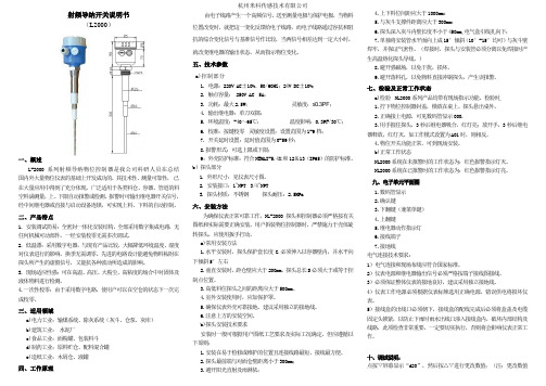
射频导纳开关说明书(L2000)一、概述L-2000系列射频导纳物位控制器是我公司科研人员在总结国内外大量物位仪表的基础上开发成功的,其技术性、测量可靠性,已在大量应用中得到了充分体现。
广泛适用于各类料仓、容器、管道的料空料满测量,上、下限自动报警或检测。
报警时可输出继电器开关信号,经中间继电器或直接与启动设备连锁,可实现上料、下料的自动控制。
二、产品特点1. 安装调试简易:全密封一体化安装结构,全部采用数字集成电路,无任何机械可动部件。
一经安装校零无需多次调试。
2. 低温漂:采用数字电器,与现有产品比较,大幅降低环境温度、湿度对仪表进行的影响,换季无需调零。
先进的电路设计能避免物料粘附在探头所产生的虚假信号,又能抗各种波动所造成的影响。
3. 现场适应性强:可在高温、高压、大粉尘、高粘度的场合中对固体及液体物料进行检测。
4.一次性校零:由于采用数字电路,使用户可以在空仓的状态下一次完成校零。
三、适用领域a)电力工业:输煤系统、除灰系统(灰斗、仓泵、灰库)b)建筑工业:水泥厂c)食品工业:面粉罐、包装料斗d)制药工业:原料贮仓、配料混合罐e)造纸工业:木屑仓、液罐四、工作原理由电子线路产生一个高频信号,送至测量电极与保护电极,当物料位置改变时,就把这一变化反馈给电子线路,而电子线路通过容抗和阻抗的综合变化信号与基准信号作比较,当两信号相差达到一定大小时,就改变继电器的输出状态,从而指示物位变化。
五、技术参数a)控制部分1. 电源:220V AC±10%,50/60HZ;24V DC±10%;2. 触点容量: 250V AC 5A;3. 功耗:最大2.5W;灵敏度:≤0.3PF;4. 输出继电器:单刀双掷;5. 环境温度:-40~65℃;温度影响:0.3PF/30℃;6. 校准:按键校零灵敏度设置:设置范围为1-9档;7. 开关延时设置:延时值范围为0-59秒;8.报警形式:可选上限或下限;9:外壳防护标准:符合NEMAI-5.4X和12&13(IP65)的防护标准。
CMCL使用手册

软起动器使用安全注意事项警告!主回路电源得电后即存在危险电压。
警告!电机停止后,主回路上依然存在危险电压,须在软起动器断电后,再打开前面板。
警告!CMC—L软起动器停止后,继电器端子上(6、7、8、9)依然存在危险电压。
警告!不允许软起动器输出端(2L1、4L2、6L3)接补偿电容器或压敏电阻。
警告!电机综合保护器应接于软起动器输入端(1L1、3L2、5L3),不允许接于输出端。
警告!软起动器与变频器混用时,二者输出端要彼此隔离。
警告!不要试图修理损坏的器件,请与供货商联系。
警告!散热器的温度可能较高(在线运行方式下)。
警告!严禁在软起动输出端反送电。
目录1.产品简介 (1)2.产品型号及收货检查 (2)3.安装 (3)4.接线 (4)& 主回路接线 (4)& 控制回路接线 (4)& 控制端子说明 (5)5.显示 (7)& 功能特点 (7)& 键盘说明 (8)& 显示状态说明 (8)6.设定及操作 (9)& 编程操作 (9)& 参数设定及说明 (9)7.维护 (10)8.故障分析 (11)9.技术参数 (13)& 一般参数 (13)& 基本接线图 (14)10.不同应用的基本设置 (15)1.产品简介及特点CMC-L系列电机软起动器是一种将电力电子技术,微处理器和自动控制相结合的新型电机起动装置。
它能无阶跃地平稳起动/停止电机,避免因采用直接起动、星/三角起动、自耦减压起动等传统的起动方式起动电机而引起的机械与电气冲击等问题,并能有效地降低起动电流及配电容量,避免增容投资。
CMC-L系列软起动器特点如下:①多起动方式:限流起动、斜坡起动、斜坡限流起动,最大程度满足现场需求,实现最佳起动效果。
②高可靠性:有高性能微处理器对控制系统中的信号进行数字化处理,避免了以往模拟线路的过多调整,从而获得极佳的准确性和执行速度。
③强大的抗干扰性:控制单元中的信号均采用光电隔离方式,并设置了不同的抗噪级别,避免了主电网上干扰引起的软起动器误动作。
电容料位开关

电容料位开关
电容料位开关一般是指采用技术超声波测量变送器在介质中的容积,从而实现介质位
置的监测控制。
它可以在管道、槽、容器内精确检测介质高度,并可以采用无接触原理测
量介质,动态方式计算介质高度,并根据结果自动控制各种介质位置。
电容料位开关又称
容位开关,是目前用于介质高度检测的被广泛应用的一种传感器,它采用容定位原理,利
用改变介质的内聚力,通过低频发出的声波进行探测介质的高度,并把检测的结果反馈给
控制系统,实现介质高度的精确控制。
电容料位开关具有良好的稳定性,测量准确率高,非接触式检测,无耗材,易于安装,使用及维护,适用于恶劣的工况,特别是腐蚀性介质和有悬浮颗粒的工况等,电容料位开
关的优点使其成为用于检测介质位置的理想选择。
电容料位开关的结构组成比较简单,主要由安装结构、发射器、接收器和控制器等组成,安装结构或容器内增设发射器和接收器,在发射器收送约500kHz-1MHz的信号,介质
里有物质时会发出回波,被接收器收集,再传到控制器,根据设置信号强度大小和反馈信
号大小比较,位置上的差距得到,从而控制输出开关控制信号。
电容料位开关的工作原理中,各个元件的性能和响应速度都有一定的影响,因此在选
择电容料位开关时,一定要确定介质特性,如液体密度,液体温度,介质表面张力,介质
对声波的反射率,介质中有其他粒子、矿物等,有些物质会影响电容料位开关的传播和检测,因此,在选择电容料位开关时,必须考虑介质特性,以确保其准确性和可靠性。
Pointek CLS300 电容触摸开关(标准版)应用示例说明书
Pointek CLS300 Capacitance Switch (Standard Version)Application examples Introduction1 Overview2 Planning/configuring3Siemens AG Digital Industries Document order number: AG080910_CLS300Ⓟ 10/2020 Subject to changeCopyright © Siemens AG 2020.All rights reservedLegal informationWarning notice systemThis manual contains notices you have to observe in order to ensure your personal safety, as well as to preventdamage to property. The notices referring to your personal safety are highlighted in the manual by a safety alertsymbol, notices referring only to property damage have no safety alert symbol. These notices shown below aregraded according to the degree of danger.DANGERindicates that death or severe personal injury will result if proper precautions are not taken.WARNINGindicates that death or severe personal injury may result if proper precautions are not taken.CAUTIONindicates that minor personal injury can result if proper precautions are not taken.NOTICEindicates that property damage can result if proper precautions are not taken.If more than one degree of danger is present, the warning notice representing the highest degree of danger willbe used. A notice warning of injury to persons with a safety alert symbol may also include a warning relating toproperty damage.Qualified PersonnelThe product/system described in this documentation may be operated only by personnel qualified for the specifictask in accordance with the relevant documentation, in particular its warning notices and safety instructions.Qualified personnel are those who, based on their training and experience, are capable of identifying risks andavoiding potential hazards when working with these products/systems.Proper use of Siemens productsNote the following:WARNINGSiemens products may only be used for the applications described in the catalog and in the relevant technicaldocumentation. If products and components from other manufacturers are used, these must be recommendedor approved by Siemens. Proper transport, storage, installation, assembly, commissioning, operation andmaintenance are required to ensure that the products operate safely and without any problems. The permissibleambient conditions must be complied with. The information in the relevant documentation must be observed. TrademarksAll names identified by ® are registered trademarks of Siemens AG. The remaining trademarks in this publicationmay be trademarks whose use by third parties for their own purposes could violate the rights of the owner. Disclaimer of LiabilityWe have reviewed the contents of this publication to ensure consistency with the hardware and softwaredescribed. Since variance cannot be precluded entirely, we cannot guarantee full consistency. However, theinformation in this publication is reviewed regularly and any necessary corrections are included in subsequenteditions.Table of contents1 Introduction (4)1.1 Objective (4)1.2 Equipment (4)1.3 Disclaimer (4)2 Overview (5)3 Planning/configuring (6)3.1 Adjusting the Setpoint (6)3.2 Pointek CLS300 Applications (6)3.3 Calibration for general applications (Failsafe low, no delay) (7)3.4 Calibration for demanding applications (Failsafe low, no delay) (7)3.5 Calibration for interface detection (Failsafe low, no delay) (7)3.6 Alarm Delay Function (8)3.7 Testing the Alarm Delay (8)3.8 Operation (8)1.1ObjectiveThe objective of this application guide is to help the user become familiar with the stepsrequired to set up and calibrate the Pointek CLS300 (Standard Version). This application guideapplies to any models manufactured after January 26, 2011.1.2Equipment1.3DisclaimerNoteWhile every effort is made to verify the following information, no warranty of accuracy orusability is expressed or implied.This application guide is an addition to the operating instructions. Please review CLS300 (Standard Version) operating instructions to ensure that the device is properly mounted. This application guide provides a basic procedure for setting the switch point for correct operation of the CLS300 (Standard Version) in either covered or uncovered states. Please note that the guide applies only to hardware manufactured after January 26, 2011 as indicated by a serial number of PBD/B127xxxx or higher. (For example, PBD/C9xxxxxx or PBD/B128xxxx.)Included in the guide are the appropriate start up procedures to quickly and effectively set up the Pointek CLS300 (Standard Version) capacitance switch for general applications, demanding applications and interface detection. It also contains instructions for adjusting the setpoint and alarm delay.For more detailed information, please consult the operating manual (A5E47827796).3.1Adjusting the SetpointBefore adjusting the setpoint or alarm delay the cover must be removed.Prior to removing the cover, please ensure that power is removed, and that the applicationand installation allow for removal of the cover. (This may not be permitted in someHazardous Areas.)Once the cover has been removed, apply power to the unit. The green power LED (L3) willglow indicating that the unit is powered and operational. If L3 is not on, please consult theSpecifications and Troubleshooting sections of the operating instructions.3.2Pointek CLS300 ApplicationsPointek CLS300 can be set up for three different applications which are described in the tablebelow. Use the calibration procedure for the application that most closely describes youroperation.Application Material Setup ConditionsGeneral •dry solids•low viscosity liquids sensor uncovered;min. 100 mm (4") free space all aroundDemanding •hygroscopic / wet solids•high viscosity and high conductivityliquids sensor immersed then uncovered; but retaining max. possible material buildupInterface detection •liquid A / liquid B•foam / liquid immerse sensor in whichever material has lowest dielectric constant3.3 Calibration for general applications (Failsafe low, no delay)3.3Calibration for general applications (Failsafe low, no delay)1.Ensure that the green power LED (L3) is on.2.Set DIP switches S1 to S5 to OFF (rocker down as shown in the diagram above).3.Turn the delay potentiometer (P1) fully counter-clockwise.4.Adjust the material level of the process so that the probe is uncovered with a minimum of100 mm (4”) free space all around.5.If the yellow sensor status LED (L1) is on, proceed to step6. If L1 is off, turn the trip pointpotentiometer (P2) counter-clockwise until it just turns on. If the yellow LED does not turnon set DIP switch S5 to ON and repeat step 5.6.Slowly turn the trip point potentiometer (P2) clockwise until the yellow sensor status LED(L1) just turns off.3.4Calibration for demanding applications (Failsafe low, no delay)1.Ensure that the green power LED (L3) is on.2.Set DIP switches S1 to S5 to OFF (rocker down as shown in the diagram above).3.Turn the delay potentiometer (P1) fully counter-clockwise.4.Adjust the material level of the process so that the sensor is immersed.5.Adjust the material level of the process so that the sensor is uncovered, but retains as muchbuildup of material as possible.6.If the yellow sensor status LED (L1) is on, proceed to step7. If L1 is off, turn the trip pointpotentiometer (P2) counter-clockwise until it just turns on. If the yellow LED does not turnon set DIP switch S5 to ON and repeat step 6.7.Slowly turn the trip point potentiometer (P2) clockwise until the yellow sensor status LED(L1) just turns off.3.5Calibration for interface detection (Failsafe low, no delay)1.Ensure that the green power LED (L3) is on.2.Set DIP switches S1 to S5 to OFF (rocker down as shown in the diagram above).3.Turn the delay potentiometer (P1) fully counter-clockwise.4.Adjust the material level of the process so that the sensor is covered by the material with thelowest relative dielectric constant.5.If the yellow sensor status LED (L1) is on, proceed to step6. If L1 is off, turn the trip pointpotentiometer (P2) counter-clockwise until it just turns on. If the yellow LED does not turnon set DIP switch S5 to ON and repeat step 5.6.Slowly turn the trip point potentiometer (P2) clockwise until the yellow sensor status LED(L1) just turns off.3.6 Alarm Delay Function3.6Alarm Delay FunctionIf you want to slow the Pointek CLS300 response, to compensate for turbulence or falsereadings, set a delay interval using the delay potentiometer (P1) and set DIP switches S1and/or S2 to the OFF position to enable the delay for either alarm activation (S1 OFF), alarmde-activation (S2 OFF), or both (S1 and S2 OFF). (Note: This information can usually be foundinside the device cover.)If an immediate alarm output is critical, disable the delay by setting the appropriate switch(either S1 or S2) to ON. The functioning of switches S1 and S2 depends on the alarm setting:3.7Testing the Alarm DelayThis test procedure assumes that you have completed one of the calibration processesdescribed previously.1.Grasp the probe with your hand. The yellow sensor status LED (L1) should turn onimmediately. The red output status LED (L2) should turn on after a delay.2.Turn the delay potentiometer (P1) clockwise about 1/8 of a turn.3.Turn DIP switch S4 to the ON position; this will simulate a change in state of the probe(covered/uncovered).4.L1 (the yellow LED) should turn on immediately, and L2 (the red LED) should turn on after alonger delay than in Step 1.5.Turn DIP switch S4 to the OFF position.6.Continue to adjust the delay potentiometer (P1) until you have the desired delay.3.8OperationAfter completing the setup, replace the lid and secure the lid clip. Pointek CLS300 Standardmodel is now ready to operate.。
- 1、下载文档前请自行甄别文档内容的完整性,平台不提供额外的编辑、内容补充、找答案等附加服务。
- 2、"仅部分预览"的文档,不可在线预览部分如存在完整性等问题,可反馈申请退款(可完整预览的文档不适用该条件!)。
- 3、如文档侵犯您的权益,请联系客服反馈,我们会尽快为您处理(人工客服工作时间:9:00-18:30)。
CLW电容料位开关
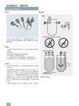
■概述
本产品采用国际上先进的射频电容技术,将容器内的物位变化量转换成电容变化量,探极作为电容的一个极板,容器壁(或辅助探极)作为另一个极板,通过电子插件把电容量的变化转换成脉冲频率的变化,将来自物位介电常数引起的信号变化给电子线路,由于电容量变化,驱动输出电路发出报警信号,从而实现料位、液位定点检测、报警或控制的目的。
■技术参数
电源电压:AC220V 50/60Hz;DC24V
相对湿度:≤85%
输出信号:一组常开、常闭触点
触点容量:AC220V,5A;DC24V,3A
环境温度:-40~+60℃
防护等级:IP65 防爆等级:ExdⅡBT4
探头材质:316不锈钢、四氟乙烯、高温塑料
功耗:≤1.5W
过程温度:普通-20~80℃;高温-25~180℃
过程压力:-0.1~4.0MPa 介电常数:ε≥1.6%
延迟时间:5秒
电气接口:M20×1.5连接方式:螺纹或法兰(见选型标记)
安装方式:顶装、侧装
■调试注意事项
CLW系列电容式物位开关灵敏度分粗调和细调
1.粗调系编码开关,他能适合对各种介质调整如矿石,孰料,水泥,煤炭,粮食,木材,麦秆,纸张。
6位编码开关由高到低调整,原则为当料位到达探极时不报警可将6位编码开关从3,2,1,顺序调整。
每拨一位开关等待5秒观察指示灯若指示灯亮说明已粗调好,(对密度高且潮湿的物料可降低其灵敏度,密度低干燥的物料可提高其灵敏度。
)
2.灵敏度细调系电位器,可调当物料粘在探极时的误动作!或者物料到达探极时精确调整,顺时针为高。
CLW系列电容式物位开关灵敏度在出厂时已调到能满足大多物位的测量。
若有特殊要求请说明!
■接线方式
CLW系列电容式料位控制器(料位开关)
·1、2位为交流220V或直流24V,3、4为常闭触点。
·4、5为常开触点。