IPVCR快速安装手册
VCS安装配置步骤58711
Veritas Cluster Server安装配置指导(针对SYBASE应用) 说明:以下所有截取图形中所有名称、IP地址等均为截图时状态,请参照实际情况修改。
一.安装前准备工作1。
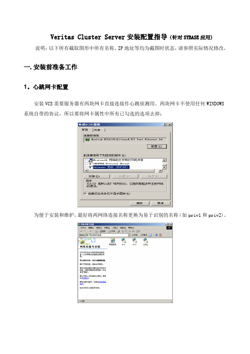
心跳网卡配置安装VCS需要服务器有两块网卡直接连接作心跳侦测用。
两块网卡不使用任何WINDOWS 系统自带的协议,所以要将网卡属性中所有已勾选的选项去掉:为便于安装和维护,最好将两网络连接名称更换为易于识别的名称(如priv1和priv2)。
2。
域配置安装VCS需要在两台服务器配置成域控制器(一主一备,或一台为主域控制器,另一台直接加入到该域)。
同时安装DNS(域名解析系统).同时最好配置一下WINS地址打开运行,填入dcpromo:安装域完成后重新启动。
3.DNS配置添加上网方法4.磁盘阵列配置首先在磁盘阵列柜上创建RAID5,同时设置一个热备盘.完成后将磁盘分两个区,同时做两个主机通道(HOST LUN)。
在每台服务器上进行如下配置:进入SCSI卡配置窗口,选择通道,进入配置视图的Advanced设置,将SCAN SCSI设备选项DISABLE或SCAN …ONLY。
目的是服务器启动时不进行SCSI设备检测,以免出错???????????????二.软件安装1.HA安装首先插入安装介质,出现安装向导:我们选择“Storage Foundation HA 4.1 for windows";在此,我们选择“Complete/Custom"选项;接着,点击“Next”;认真阅读软件许可协议后选择“I accept the terms of the license agreement”继续;输入license key,点“ADD”,然后NEXT;选中“VERITAS Storage Foundation HA 4。
1 for Windows”,点击“Next”;此处,是选择需要安装的Agent,选择后点“Next”;选择需要安装VCS的服务器,点击“ADD”,然后选择安装目录,默认为:c:\program files\veritas\,点“Next”继续;屏幕显示安装选项报告。
iPECS-MG_快速安装指南

3.4.1 3.4.2 3.4.3 3.4.4 SLIB12/24 (模拟分机接口板) ..................................................................................................................................... 17 SLIB12C/24C (用 RJ21 连接头) ................................................................................................................................. 18 DTIB12/24 (数字终端接口板) ..................................................................................................................................... 18 DTIB12C/24C (用 RJ21 连接头) .................................................................................................................................. 19
快速安装手册

快速安装手册快速安裝手冊1、購買DIGIZON後請先清點配件是否齊全如圖1、D IGIZON本體× 12、A V訊號轉接線× 23、S端連接線× 14、C ABLE同軸線× 15、紅外線發射頭× 16、N TSC訊號轉接頭×27、C AT5網路線×18、電源限線×19、光碟片×1若有缺件請洽經銷商1236457 822、先將電視天線或有線電視的CABLE同軸線,利用DIGIZON所附的NTSC訊號轉接頭接上DIGIZON的天線輸入端,再由DIGIZON內置的匹配器輸出端,將訊號接到電視機上3.使用網路線將DIGIZON接上網路(請先確家中認網路是良好暢通可連上網際網路)。
IP分享器或無線基地台4、將DIGIZON插上電源。
並將電源開啟(請按黃色按鍵)5.確定電源燈有亮(POWER)6.確定網燈有亮(NETWORK)7、完成硬體安裝如圖8、在PC或NB上安裝軟體請先確認你的電腦需具備之規格如下:作業系統:WINDOWS 2000,ME,XP(with Direct X9.0c or above C)CPU:Pentium 4, 1.2GHz or above (MMX,SSE and SSE2 support)記憶體Memory:256 MB above顯示卡Display:DirectX compatible音效卡Sound Card:DirectX compatible建議顯示器最佳設定:解析度1024×768 32-bits Color bit將所附軟體光碟放入光碟機開始安裝軟體如圖雙擊DIGIZON setup開始安裝。
9、選擇英文English或中文Chinese(Taiwan)按ok開始安裝10、開始安裝11、顯示安裝的路徑和資料夾若須更改請按瀏覽自行變更若不更改請按下一步繼續。
12、程式安裝中13、安裝成功圖示出現後請按結束(Finish)。
剪枝VL电源保护设备安装与操作指南说明书

CLIPPER VL INSTALLATION & OPERATINGMANUALCLIPPER VLINSTALLATION & OPERATING MANUALThis manual applies to all Clipper VL Nema 1, Nema 3R and Flush mount versions.1.0 IntroductionCongratulations on your purchase of this Surge Protective Device (SPD). The Clipper VL is a SPD that protects sensitive electronic equipment from damaging transients, surges and electrical line noise. Proper installation is critical to ensure this unit operates as intended. This SPD is a built-in device and all wiring must be protected against direct contact. The relay contacts should not be used with SELV or PELV circuits.Type IEC ClimaticConditionIPRatingIP Ratingwith CircuitNEMA 13K32141 NEMA 3R4K4H2242If you need to protect this device against dust ingress (for example in pulverized fuel plants or cement works), please use an enclosure with the appropriate IP classification.Please read the installation and operating instructions prior to using this SPD.2.0 Preparation2.1 Verify that the electrical distribution system voltage and wiring configuration are the same as that of the enclosed SPD by checking the voltage-rating label located on the inside cover.2.2 Check the facility grounding system. All grounding, bonding and earthing practices must meet NEC, CEC and local approved practices. A poor ground, or grounding/bonding violations, seriously affect the SPD's ability to function as specified.3.0 Installation Procedures3.1 Locate an available 15 AMP breaker space immediately after the main breaker in the electrical equipment being protected. If this position is not available, identify the next closest breaker space. Note that fuses rated 600V, 15 AMP can be used inplace of the circuit breaker described here.3.2 If there is no space available within the electrical equipment, locate the closest existing 15 AMP breaker within the electrical equipment.3.3 To ensure maximum effectiveness and provide the best possible protection for the sensitive electrical equipment, the SPD must be installed as close to the electrical equipment as possible.The 14 AWG wire lead length between the SPD and installation breaker should be 35 cm (14”) or less.NOTE: Twist the wires tightly together. Minimize overall lead length to optimize SPD performance.3.4 Turn OFF the power to the electrical equipment where the SPD is to be installed.3.5Install a 15 AMP branch circuit breaker to feed the SPD (if space is not available refer to 3.2)3.6 The Clipper VL may be installed using a standard knockout. If so, remove lock-nut from nipple, insert nipple and 14 AWG wires through knockout, re-install lock-nut and tighten. If not installed directly into the electrical equipment use a metal conduit (rigid or flexible) between the SPD and the electrical equipment. For NEMA 3R applications use watertight conduit and glands, and ensure the Clipper VL is mounted with the nipple pointing in the downward direction and the driphood in the upright direction.3.7 Run the 14 AWG wires from the SPD to the electricalequipment.3.8 Strip the ends of the wires and terminate at the line side terminals of the identified branch breaker mounted within the electrical equipment. Tighten all connections 3.9 Recheck all connections.3.10 Switch the MAIN power to the ON position for the electrical equipment and SPD.3.11 Check all status indicator lamps to verify system operation (see maintenance and operating procedures).3.12 If a remote monitoring option is required, connect the Form C Contacts to an alarm or building monitoring system.These relay contacts are rated at:AC - 125 V, 60 VA, 1 Amp.DC - 150 V, 30 W, 1 Amp.Figure 1: Clipper VL Wiring ExamplesWIRE COLOR CODEMODECVLL1 (A)RED L2 (B)WHITE L3 (C)BLACK NEUTRAL BLUEGROUND/PEGREEN/YELLOWFigure 2: Dimension Details4.0 Diagnostics and Safety Features4.1 Status Indicator Lights. To keep you informed of the SPD’s operating status, each phase is equipped with green indicator lights. When illuminated, the system is operating properly. If the lamps are off, a problem may exist within the SPD.The Clipper VL is also provided with a green status indicator lamp, that monitors individual MOVs. If a fault is found with any MOV, this lamp turns off to indicate a problem.The audible alarm and Form C Contacts are tied to the main status indicator lights and will sound/switch in the event of a problem.5.0 Ten Year WarrantyCutler-Hammer warrants the Clipper VL SPD for a period of ten years from the date of delivery to the purchaser to be free from defects in both workmanship and materials. Cutler-Hammer assumes no risk or liability for results of the use of the products purchased from it, including but without limiting the generality of the foregoing: (1) The use in combination with any electrical or electronic components, circuits, systems, assemblies or any other materials or substances. (2) Unsuitability of any product for use in any circuit or assembly. Purchaser’s rights under the warranty shall consist solely of requiring Cutler-Hammer to repair, or at Cutler-Hammer’s sole discretion, replace, free of charge, F.O.B. factory, any defective items received at said factory within said term determined by Cutler-Hammer to be defective. The giving of or failure to give any advice or recommendations by Cutler-Hammer shall not constitute any warranty by or impose any liability upon Cutler-Hammer AND IS IN LIEU OF ANY AND ALL OTHER WARRANTIES EXPRESSED, IMPLIED OR STATUTORY AS TO THE MERCHANTABILITY, FITNESS FOR PURPOSE SOLD, DESCRIPTION, QUALITY, PRODUCTIVENESS OR ANY OTHER MATTER. In no event shall Cutler-Hammer be liable for special or consequential damages or for delay in performance of the warranty.This warranty does not apply if the unit has been misused, abused, altered, tampered with, or applied in excess of the specifications other than those written on the nameplate. At the end of the warranty period Cutler-Hammer shall be under no further warranty obligation expressed or implied. The Clipper VL SPD covered by this warranty certificate can only be repaired or replaced by the factory. A RETURN PRODUCT NUMBER (R.P.N.) must be obtained and be clearly marked on the outside of the shipping container as well as on the unit being returned. It should be forwarded, freight, brokerage and Duty Prepaid to: Cutler-Hammer, #10, 2256-29th Street N.E., Calgary, AB, Canada, T1Y 7G4, (403) 717-2000, Fax: (403) 717-0567, with a detailed description of the fault, your name, address and telephone number. Repair or replacement will be returned customer collect. If Cutler-Hammer finds the return is the result of a manufacturer’s defect, the unit will be returned prepaid.6.0 Troubleshooting GuideThe Clipper VL SPD requires no maintenance.If any green light is off, the unit requires replacement. Call Cutler-Hammer to arrange delivery for a replacement unit. U.S.A. – 1-800-525-2000CANADA - 1-800-524-5004。
ispLEVER5.0简明中文教程(CPLD篇)

ispLEVER5.0简明中⽂教程(CPLD篇)Lattice CPLD/FPGA 开发⼯具ispLEVER5.0 简明中⽂教程(CPLD篇)黄俊2005年7⽉概述ispLEVER是Lattice(莱迪思)的数字设计⼯具套件,它⽀持莱迪思所有的FPGA、CPLD、ispGDX和SPLD器件。
ispLEVER包含Lattice以及业界领先者们所开发的⼯具,⽤于设计输⼊、综合、验证/仿真、适配、布局和布线以及器件编程。
本⽂简要说明了ispLEVER中的各种⼯具的使⽤⽅法,并说明如何查看ispLEVER中的报告。
本篇以⼀个简单的4位⽐较器为例介绍开发CPLD的流程,最后还重点介绍了在CPLD开发中占⼀定⽐例的原理图编辑法。
关于Help⽂件z学习⼀个软件的最佳途径就是学习它的Help,ispLEVER的Help⽂档⾮常详细,不仅有对软件各功能的详细解释还学习指南;z⽤户可以在软件的任何环境下按F1打开Help;z在不同的窗⼝下的菜单栏内点击Help菜单,即可以打开相应的Help⽂件;z为尽快掌握ispLEVER的操作,⽤户也可以联系代理商以安排软件培训。
在这⾥做个⼴告,我们公司——晏阳科技(总公司为彦阳科技)是Lattice的代理商之⼀,本⼈是深圳办事处的⼀名应⽤⼯程师,客户主要在福建和深圳。
我们深圳办事处的总机号码是0755-********,传真是0755-********。
福州联络处的电话是:0591-********系统需求z若开发CPLD,建议内存256M以上,推荐512M;z若开发FPGA,建议内存512M以上,推荐768M;z强烈建议使⽤Windows XP系统。
软件安装1、放⼊安装光盘,ispLEVER Setup会⾃动启动。
2、选第三项Install ispLEVER 5.0 Design Tools(第4项Install PAC-Designer 3.4是安装Lattice PAC系列产品的开发软件,⽀持在系统可编程模拟器件ispPAC,在系统可编程电源管理芯⽚ispPAC-POWER,本⼈也写了⼀篇关于该软件的中⽂说明)3、⼀直点Next:设定安装路径,⼀路点Next,:4、到以上页⾯时,选择需要安装器件和开发⼯具。
IPC安装说明书
Camera Use manual Camera UseWhat’s In the IPC Set?What s In the IPC Set?•IPC X 1Mini USB cable x 1•Mini USB cable x1•5V / 1A power adapter x 1•Reset pin x 1一、Setting ProcedureDownload & install the software Download&install the softwareCloud2Me android version V1.0.1.15a can download Cloud2Me android version-V10115a can download and install the Google paly market, ios version -V1.0.4 can download and install the app storeOr you can directly download and install the following linkli kAndroid version:https:///store/apps/details?id=com.Cloud2MeIos version :https:///cn/app/cloud2me/id989081394?mt=8Step 1, 2, 3p ,,231Plug the power cordWait 20seconds,thenHear "beep"sound,Wait 20 seconds, then insert a reset pinHear beep sound, while flashing yellowlight.Step 4,5,6Step 4, 5, 6465Start App, selectClick OK SignClick the Add login modeCameraStep 7,8,9Step 7, 8, 9789Confirm flashing yellow light, or Enter WIFI InformationReady to sweep the two-dimensionalre-operate the second stepcodeStep10,11Step 10, 1110 cm ~ 15 cm11 1010~20cmC iiClick to add online cameraTo watch10 20 cm•Use IPC scan two-dimensional code, the twodistance of 10 to 20 cm.•Wait adding results•Webcam added successfully•Voice: Scan successful, click NextTo watch,•LED: Yellow flashing•IPC On-line :Voice: the camera head the line.LED: Green lightStep 12,13,14Step 12, 13, 14121413Click drop-down button make other Select the item to be set Click the settingsyou can set alarm notifications, button, make other settingsto be setadjust the sound, unbundling cameras operateStep 15,16,17Step 15, 16, 17161517Click the alarm notification can view alarm recordsClick Share to share with friends back through the micro After clicking the camera canno longer use the unbundling g channel g g of the cameraPROMPT :二、Frequently Asked Questions 二Frequently Asked Questions。
ITCIP网络广播系统调试安装手册

IP网络广播系统安装调试部分用户使用手册目录系统服务器软件软件安装:运行光盘或者下载压缩包根目录下的“ITCcast.exe”文件,计算机将弹出程序安装向导,在系统提示“请输入密码”的地方输入由升和公司提供的安装密码,单击【下一步】按钮直到安装提示系统软件安装完成,系统将在开始→程序菜单中生成“升和IP网络广播”程序组,同时在系统桌面上生成启动与配置的快捷方式。
系统软件界面示例:软件卸载:在开始→程序→升和IP网络广播中提供了卸载系统服务器的快捷方式,同时可以在开始→控制面板→升和IP网络广播Ver2.0中卸载系统软件。
软件注册:本系统需要正确注册才能正常使用,注册方法如下:1.使用管理员身份登陆系统服务器,打开帮助→软件注册。
2.在弹出的窗口界面如下图所示,将【用户序列号】反馈给代理商。
3.将获得的“系统注册码”输入【系统注册码】一栏,然后点击【注册】,完成注册,界面如下图。
远程客户端软件安装软件获取:软件可以通过以下两种途径获取:随机光盘:在光盘根目录下的“itccast.exe”文件。
软件安装:运行光盘或者下载压缩包根目录下的“itccast.exe”文件,计算机将弹出程序安装向导,在系统提示“请输入密码”的地方输入由升和公司提供的安装密码,在系统提示“选择安装组件”的地方单击下拉菜单选择“远程客户端”,然后单击【下一步】按钮直到安装提示客户端软件安装完成。
安装完成后,系统将在开始→程序菜单中生成“升和IP网络广播”,同时在系统桌面上生成启动的快捷方式。
软件卸载:在开始→程序→升和IP网络广播中提供了卸载客户端软件的快捷方式,同时可以在开始→控制面板→升和IP网络广播Ver2.0中卸载客户端软件。
客户端软件界面示例:预设置终端参数设置前准备:在配置前,必须做一个总体的安装规划:包括终端名称、终端IP地址、网关IP地址、服务器IP地址、终端安装的物理位置,并且把这些信息做成标签贴在终端上,保证安装的顺利实施。
IPVCR 用户手册 (1)

Codian IPVCR 用户手册上海神州数码信息技术服务有限公司黄晔旻2008年12月目录第一章安装 (3)1.连接IPVCR到您的网络 (3)2.设置IPVCR的网络IP地址 (4)3.登陆IPVCR (4)4.选择H.323网守 (7)5.注册内网已经具备的H.323网守 (8)6.注册IPVCR自己的H.323网守 (8)第二章创建录制 (11)1.由IPVCR呼出的录制 (11)2.由IPVCR呼出的可监控录制 (14)3.由终端呼出的点对点录制 (15)4.由IPVCR呼出的会议录制 (15)5.由MCU呼出,IPVCR接收的会议录制 (16)第三章播放录像 (18)1.由电脑来观看录制的会议 (18)2.由视频终端来观看录制的会议 (20)3.使用AUTO ATTENDANT来观看录制的会议内容 (20)1.H.239双路视频选项 (21)2.添加终端选项 (21)3.用户权限选项 (22)第一章安装1.连接IPVCR到您的网络这一部分主要讲解安装IPVCR以及登陆IPVCR的一些操作和命令在您对IPVCR设备进行加电之前:使用蓝色的串口线缆连接至IPVCR的串口启用您的串口程序,并按照以下接口数据进行连接使用网线连接IPVCR的以太网口A至您的以太网交换机(非Hub)IPVCR的以太网速率支持10/100/1000Mbps自动协商连接电源线,开启电源IPVCR没有on/off的电源开关2.设置IPVCR的网络IP地址等到IPVCR面板上的红色警告灯熄灭后,在您的串口程序上显示内容如下:IPVCR默认为DHCP模式,当然您也可以手动设定固定IP地址。
手动设定DHCP的命令如下:手动设定固定IP地址的命令如下:如若没有DNS服务器,您可以设定您的默认网管地址------其中的任何一项都需要设定检查IP设定的状态命令---status,察看命令的命令---help,察看命令语法的命令---“命令”+“回车”3.登陆IPVCR您目前已经可以通过WEB浏览器,敲入您设定的IPVCR的IP地址来登陆IPVCR。
- 1、下载文档前请自行甄别文档内容的完整性,平台不提供额外的编辑、内容补充、找答案等附加服务。
- 2、"仅部分预览"的文档,不可在线预览部分如存在完整性等问题,可反馈申请退款(可完整预览的文档不适用该条件!)。
- 3、如文档侵犯您的权益,请联系客服反馈,我们会尽快为您处理(人工客服工作时间:9:00-18:30)。
简易用户手册TANDBERG 录播服务器
版本1.0
目录
一、物理接线 (3)
二、开启系统 (4)
三、主要配置 (5)
3.1初始配置 (5)
3.2录制号码 (7)
3.3高清录制 (9)
3.4系统配置 (9)
3.5 H.323配置 (10)
3.6 SIP配置 (11)
四、回放操作 (12)
4.1Web界面检查录制文件 (12)
4.2Web界面回放 (12)
4.3录制下载 (13)
4.4格式转换 (15)
五、故障排查 (16)
5.1Web界面回放故障 (16)
5.2系统日志 (18)
一、物理接线
二、开启系统
开机:接上电源即可,无开关设计Web界面关机:设置 > 关机.
三、主要配置
3.1初始配置
1,步骤一
连接以太网口A到交换机,该网口为10/100/1000Mbps网口。
网口B供未来使用。
2,步骤二
连接到串口
确定IPVCR正常供电,同时面板状态指示灯正常。
用串口终端程序连接,例如HyperTerminal连接到系统控制板
串口终端程序配置如下:
∙比特率: 38400
∙数据位: 8
∙奇偶位: 无
∙停止位: 1
∙流量控制:无
按回车键后将得到如下提示符:
IPVCR:>
3,步骤三:配置以太网口A
以太网速率为自动协商:ethertype auto
显示以太网口状态:status
4,步骤四:配置以太网口IP
静态指定:static <IP address> <netmask> <default gateway address><DNS server address>
例如:static 192.168.1.2 255.255.255.0 192.168.1.1 0.0.0.0
显示IP地址:status
5,步骤五:剩下的配置通过配好的IP地址Web界面操作
缺省用户名:admin,密码无
变更登录身份
管理员身份登录后界面
文件夹配置
录制号码设置
检查设置
3.3高清录制
3.4系统配置
连通测试界面
测试结果
3.5 H.323配置设置网守
3.6 SIP配置
四、回放操作
4.1Web界面检查录制文件
编码转换
4.2Web界面回放
转换完毕后可以观看
选择带宽和媒体类型
开始
4.3录制下载
第一步:点击录好的文件
第二步:选择下载
可以选择MPEG1格式(.mpg)或者原始格式(.codian)下载
下载原始格式
4.4格式转换
将*.codian后缀的文件转换成*.mpg和*.wmv文件。
Codian Converters软件,
下载地址:
/pub/software/ip_vcr_2200/converter_tools/10/主页
转换输出
输入文件
五、故障排查
5.1Web界面回放故障
5.2系统日志。