STM32工程建立(F4系列)
stm32f4 标准库例程

stm32f4 标准库例程
STM32F4标准库例程是针对STMicroelectronics的STM32F4系列微控制器的软件库。
该库提供了一系列的API和函数来简化开发过程,包括GPIO、UART、SPI、I2C、ADC等常见外设的控制。
标准库例程分为两部分:库函数和示例代码。
库函数提供了一系列api和函数,可以直接在用户代码里调用来方便地控制外设。
示例代码则提供了一系列完整的项目范例,用户可以根据需要来学习和修改。
库函数包括各种外设的初始化、读写寄存器等操作。
例如,GPIO部分提供了GPIO初始化和控制函数、EXTI中断控制函数等;USART部分提供了串口初始化、发送、接收等函数;SPI部分提供了SPI初始化、配置、发送、接收等函数;ADC部分提供了ADC初始化、采样、转换等函数。
总之,这些库函数为开发者提供了许多方便和帮助。
示例代码则为用户提供了许多完整的项目实例,包括blinking LED实验、串口通信实验、SPI通信实验、I2C通信实验、ADC采样实验等。
用户可以通过学习这些示例代码,了解如何使用库函数控制外设。
总的来说,STM32F4标准库例程是STM32F4系列微控制器开发的重要工具,为用户提供了方便的API和函数,以及完整的示例代码,帮助用户更好的理解
和掌握STM32F4微控制器的开发。
STM32F4使用手册

January 2014DocID022256 Rev 41/42IntroductionThe STM32F4DISCOVERY helps you to discover the STM32F407 & STM32F417 lines’ high-performance features and to develop your applications.It is based on an STM32F407VGT6 and includes an ST-LINK/V2 embedded debug tool interface, ST MEMS digital accelerometer, ST MEMS digital microphone, audio DAC with integrated class D speaker driver, LEDs, pushbuttons and a USB OTG micro-AB connector.1.Picture not contractualContents UM1472Contents1Conventions . . . . . . . . . . . . . . . . . . . . . . . . . . . . . . . . . . . . . . . . . . . . . . . . 52Quick start . . . . . . . . . . . . . . . . . . . . . . . . . . . . . . . . . . . . . . . . . . . . . . . . . 62.1Getting started . . . . . . . . . . . . . . . . . . . . . . . . . . . . . . . . . . . . . . . . . . . . . . 62.2System requirements . . . . . . . . . . . . . . . . . . . . . . . . . . . . . . . . . . . . . . . . . 62.3Development toolchain supporting the STM32F4DISCOVERY . . . . . . . . . 62.4Order code . . . . . . . . . . . . . . . . . . . . . . . . . . . . . . . . . . . . . . . . . . . . . . . . . 6 3Features . . . . . . . . . . . . . . . . . . . . . . . . . . . . . . . . . . . . . . . . . . . . . . . . . . . 74Hardware and layout . . . . . . . . . . . . . . . . . . . . . . . . . . . . . . . . . . . . . . . . . 84.1STM32F407VGT6 microcontroller . . . . . . . . . . . . . . . . . . . . . . . . . . . . . . 114.2Embedded ST-LINK/V2 . . . . . . . . . . . . . . . . . . . . . . . . . . . . . . . . . . . . . . 134.2.1Using ST-LINK/V2 to program/debug the STM32F4 on board . . . . . . .144.2.2Using ST-LINK/V2 to program/debug an external STM32 application . .154.3Power supply and power selection . . . . . . . . . . . . . . . . . . . . . . . . . . . . . . 164.4LEDs . . . . . . . . . . . . . . . . . . . . . . . . . . . . . . . . . . . . . . . . . . . . . . . . . . . . . 164.5Pushbuttons . . . . . . . . . . . . . . . . . . . . . . . . . . . . . . . . . . . . . . . . . . . . . . . 164.6On board audio capability . . . . . . . . . . . . . . . . . . . . . . . . . . . . . . . . . . . . . 174.7USB OTG supported . . . . . . . . . . . . . . . . . . . . . . . . . . . . . . . . . . . . . . . . 174.8Motion sensor (ST MEMS LIS302DL or LIS3DSH) . . . . . . . . . . . . . . . . . 174.9JP1 (Idd) . . . . . . . . . . . . . . . . . . . . . . . . . . . . . . . . . . . . . . . . . . . . . . . . . . 184.10OSC clock . . . . . . . . . . . . . . . . . . . . . . . . . . . . . . . . . . . . . . . . . . . . . . . . 194.10.1OSC clock supply . . . . . . . . . . . . . . . . . . . . . . . . . . . . . . . . . . . . . . . . .194.10.2OSC 32KHz clock supply . . . . . . . . . . . . . . . . . . . . . . . . . . . . . . . . . . .194.11Solder bridges . . . . . . . . . . . . . . . . . . . . . . . . . . . . . . . . . . . . . . . . . . . . . 204.12Extension connectors . . . . . . . . . . . . . . . . . . . . . . . . . . . . . . . . . . . . . . . . 21 5Mechanical drawing . . . . . . . . . . . . . . . . . . . . . . . . . . . . . . . . . . . . . . . . 34 6Electrical schematics . . . . . . . . . . . . . . . . . . . . . . . . . . . . . . . . . . . . . . . 35 7Revision history . . . . . . . . . . . . . . . . . . . . . . . . . . . . . . . . . . . . . . . . . . . 41UM1472List of tables List of tablesTable 1.ON/OFF conventions . . . . . . . . . . . . . . . . . . . . . . . . . . . . . . . . . . . . . . . . . . . . . . . . . . . . . .5 Table 2.Jumper states. . . . . . . . . . . . . . . . . . . . . . . . . . . . . . . . . . . . . . . . . . . . . . . . . . . . . . . . . . .13 Table 3.Debug connector CN2 (SWD). . . . . . . . . . . . . . . . . . . . . . . . . . . . . . . . . . . . . . . . . . . . . . .15 Table 4.Solder bridges. . . . . . . . . . . . . . . . . . . . . . . . . . . . . . . . . . . . . . . . . . . . . . . . . . . . . . . . . . .20 Table 5.MCU pin description versus board function . . . . . . . . . . . . . . . . . . . . . . . . . . . . . . . . . . . .21 Table 6.Document revision history. . . . . . . . . . . . . . . . . . . . . . . . . . . . . . . . . . . . . . . . . . . . . . . . . .41List of figures UM1472 List of figuresFigure 1.STM32F4DISCOVERY. . . . . . . . . . . . . . . . . . . . . . . . . . . . . . . . . . . . . . . . . . . . . . . . . . . . .1 Figure 2.Hardware block diagram . . . . . . . . . . . . . . . . . . . . . . . . . . . . . . . . . . . . . . . . . . . . . . . . . . .8 Figure 3.Top layout . . . . . . . . . . . . . . . . . . . . . . . . . . . . . . . . . . . . . . . . . . . . . . . . . . . . . . . . . . . . . .9 Figure 4.Bottom layout . . . . . . . . . . . . . . . . . . . . . . . . . . . . . . . . . . . . . . . . . . . . . . . . . . . . . . . . . . .10 Figure 5.STM32F407VGT6 package . . . . . . . . . . . . . . . . . . . . . . . . . . . . . . . . . . . . . . . . . . . . . . . .11 Figure 6.STM32F407VGT6 block diagram . . . . . . . . . . . . . . . . . . . . . . . . . . . . . . . . . . . . . . . . . . .12 Figure 7.Typical configuration . . . . . . . . . . . . . . . . . . . . . . . . . . . . . . . . . . . . . . . . . . . . . . . . . . . . .13 Figure 8.STM32F4DISCOVERY connections image . . . . . . . . . . . . . . . . . . . . . . . . . . . . . . . . . . . .14 Figure 9.ST-Link connections image. . . . . . . . . . . . . . . . . . . . . . . . . . . . . . . . . . . . . . . . . . . . . . . . .15 Figure 10.STM32F4DISCOVERY mechanical drawing . . . . . . . . . . . . . . . . . . . . . . . . . . . . . . . . . . .34 Figure 11.STM32F4DISCOVERY. . . . . . . . . . . . . . . . . . . . . . . . . . . . . . . . . . . . . . . . . . . . . . . . . . . .35 Figure 12.ST-LINK/V2 (SWD only). . . . . . . . . . . . . . . . . . . . . . . . . . . . . . . . . . . . . . . . . . . . . . . . . . .36 Figure 13.MCU . . . . . . . . . . . . . . . . . . . . . . . . . . . . . . . . . . . . . . . . . . . . . . . . . . . . . . . . . . . . . . . . . .37 Figure 14.Audio. . . . . . . . . . . . . . . . . . . . . . . . . . . . . . . . . . . . . . . . . . . . . . . . . . . . . . . . . . . . . . . . . .38 Figure B_OTG_FS . . . . . . . . . . . . . . . . . . . . . . . . . . . . . . . . . . . . . . . . . . . . . . . . . . . . . . . . . .39 Figure 16.Peripherals . . . . . . . . . . . . . . . . . . . . . . . . . . . . . . . . . . . . . . . . . . . . . . . . . . . . . . . . . . . . .40UM1472Conventions 1 ConventionsTable1 provides the definition of some conventions used in the present document.Quick start UM14722 Quick startThe STM32F4DISCOVERY is a low-cost and easy-to-use development kit to quicklyevaluate and start a development with an STM32F4 high-performance microcontroller.Before installing and using the product, please accept the Evaluation Product License Agreement from /stm32f4-discovery.For more information on the STM32F4DISCOVERY and for demonstration software, visit /stm32f4-discovery.2.1 Getting startedFollow the sequence below to configure the STM32F4DISCOVERY board and launch theDISCOVER application:1.Check jumper position on the board, JP1 on, CN3 on (DISCOVERY selected).2. Connect the STM32F4DISCOVERY board to a PC with a USB cable ‘type A to mini-B’through USB connector CN1 to power the board. Red LED LD2 (PWR) then lights up.3. Four LEDs between B1 and B2 buttons are blinking.4. Press user button B1 to enable the ST MEMS sensor, move the board and observe thefour LEDs blinking according to the motion direction and speed. (If you connect asecond USB cable ‘type A to micro-B’ between PC and CN5 connector then the board is recognized as standard mouse and its motion will also control the PC cursor).5. To study or modify the DISCOVER project related to this demo, visit/stm32f4-discovery and follow the tutorial.6. Discover the STM32F4 features, download and execute programs proposed in the listof projects.7. Develop your own application using available examples.2.2 System requirements•Windows PC (XP , Vista, 7)•USB type A to Mini-B USB cable2.3 Development toolchain supporting the STM32F4DISCOVERY•Altium, TASKING™ VX-Toolset •Atollic TrueSTUDIO ®•IAR Embedded Workbench ® for ARM (EWARM) •Keil™, MDK-ARM2.4 Order codeTo order the STM32F4 high-performance discovery board, use the order codeSTM32F4DISCOVERY .UM1472Features 3 FeaturesThe STM32F4DISCOVERY offers the following features:•STM32F407VGT6 microcontroller featuring 1MB of Flash memory, 192 KB of RAM in an LQFP100 package•On-board ST-LINK/V2 with selection mode switch to use the kit as a standalone ST-LINK/V2 (with SWD connector for programming and debugging)•Board power supply: through USB bus or from an external 5V supply voltage•External application power supply: 3V and 5V•LIS302DL or LIS3DSH, ST MEMS motion sensor, 3-axis digital output accelerometer•MP45DT02, ST MEMS audio sensor, omnidirectional digital microphone•CS43L22, audio DAC with integrated class D speaker driver•Eight LEDs:–LD1 (red/green) for USB communication–LD2 (red) for 3.3V power on–Four user LEDs, LD3 (orange), LD4 (green), LD5 (red) and LD6 (blue)– 2 USB OTG LEDs LD7 (green) VBus and LD8 (red) over-current•Two pushbuttons (user and reset)•USB OTG with micro-AB connector•Extension header for LQFP100 I/Os for quick connection to prototyping board and easy probingHardware and layout UM1472 4 Hardware and layoutThe STM32F4DISCOVERY is designed around the STM32F407VGT6 microcontroller in a100-pin LQFP package.Figure2 illustrates the connections between the STM32F407VGT6 and its peripherals (ST-LINK/V2, pushbutton, LED, Audio DAC, USB, ST MEMS accelerometer, ST MEMSmicrophone, and connectors).Figure3 and Figure4 help you to locate these features on the STM32F4DISCOVERY.UM1472Hardware and layoutNote:Pin 1 of CN2, CN3, JP1, P1 and P2 connectors are identified by a square.Hardware and layout UM14724.1 STM32F407VGT6 microcontrollerThis ARM Cortex-M4 32-bit MCU with FPU has 210 DMIPS, up to 1 MB Flash/192+4KB RAM, USB OTG HS/FS, Ethernet, 17 TIMs, 3 ADCs, 15 comm. interfaces and a camera.Figure 5. STM32F407VGT6 packageThis device provides the following benefits.•168 MHz/210 DMIPS Cortex-M4 with single cycle DSP MAC and floating point unitproviding:Boosted execution of control algorithms More features possible for your applications Ease of useBetter code efficiency Faster time to marketElimination of scaling and saturation Easier support for meta-language tools •Designed for high performance and ultra fast data transfers; ART Accelerator, 32-bit, 7-layer AHB bus matrix with 7 masters and 8 slaves including 2 blocks of SRAM, MultiDMA controllers: 2 general purpose, 1 for USB HS, 1 for Ethernet, One SRAM block dedicated to the core, providing performance equivalent to 0-wait execution from Flash Concurrent execution and data transfers and simplified resource allocation •Outstanding power efficiency; Ultra-low dynamic power, RTC <1 μA typical in VBATmode, 3.6 V down to 1.7 V VDD, Voltage regulator with power scaling capability,providing extra flexibility to reduce power consumption for applications requiring both high processing and low power performance when running at low voltage or on a rechargeable battery •Maximum integration: Up to 1 Mbyte of on-chip Flash memory, 192 Kbytes of SRAM,reset circuit, internal RCs, PLLs, WLCSP package available, providing more features in space constrained applications •Superior and innovative peripherals providing new possibilities to connect andcommunicate high speed data and more precision due to high resolution •Extensive tools and software solutions providing a wide choice within the STM32ecosystem to develop your applications.-3 634- & 6'4-BYTE OF &LASH MEMORY +BYTES OF 2!-,1&0 X MM4.2 Embedded ST-LINK/V2The ST-LINK/V2 programming and debugging tool is integrated on theSTM32F4DISCOVERY. The embedded ST-LINK/V2 can be used in 2 different ways according to the jumper states (see Table 2): •Program/debug the MCU on board, •Program/debug an MCU in an external application board using a cable connected toSWD connector CN2. The embedded ST-LINK/V2 supports only SWD for STM32 devices. For information about debugging and programming features refer to user manual UM1075 (ST-LINK/V2 in-circuit debugger/programmer for STM8 and STM32) which describes in detail all the ST-LINK/V2 features.Figure 7. Typical configuration-3 6(ARDWARE REQUIREMENTS 53" CABLE TYPE ! TO MINI "COMPUTER WITH 7INDOWS 80 6ISTA OR $EVELOPMENT TOOLCHAIN!LTIUM 4!3+).' 68 4OOLSET !TOLLIC 4RUE345$)/)!2 %7!2-+EIL -$+ !2-4.2.1 Using ST-LINK/V2 to program/debug the STM32F4 on boardTo program the STM32F4 on board, simply plug in the two jumpers on CN3, as shown inFigure8 in red, but do not use the CN2 connector as that could disturb communication withthe STM32F407VGT6 of the STM32F4DISCOVERY.06Y 94.2.2 Using ST-LINK/V2 to program/debug an external STM32 applicationIt is very easy to use the ST-LINK/V2 to program the STM32 on an external application.Simply remove the 2 jumpers from CN3 as shown in Figure9, and connect your applicationto the CN2 debug connector according to Table3.Note:SB11 must be OFF if you use CN2 pin 5 in your external application.06Y 9DocID022256 Rev 44.3 Power supply and power selectionThe power supply is provided either by the host PC through the USB cable, or by anexternal 5V power supply.The D1 and D2 diodes protect the 5V and 3V pins from external power supplies:•5V and 3V can be used as output power supplies when another application board is connected to pins P1 and P2.In this case, the 5V and 3V pins deliver a 5V or 3V power supply and powermA.consumption must be lower than 100•5V can also be used as input power supplies e.g. when the USB connector is not connected to the PC.In this case, the STM32F4DISCOVERY board must be powered by a power supply unitor by auxiliary equipment complying with standard EN-60950-1: 2006+A11/2009, andmust be Safety Extra Low Voltage (SELV) with limited power capability.4.4 LEDs•LD1 COM: LD1 default status is red. LD1 turns to green to indicate thatcommunications are in progress between the PC and the ST-LINK/V2.•LD2 PWR: red LED indicates that the board is powered.•User LD3: orange LED is a user LED connected to the I/O PD13 of theSTM32F407VGT6.•User LD4: green LED is a user LED connected to the I/O PD12 of theSTM32F407VGT6.•User LD5: red LED is a user LED connected to the I/O PD14 of the STM32F407VGT6.•User LD6: blue LED is a user LED connected to the I/O PD15 of the STM32F407VGT6.•USB LD7: green LED indicates when VBUS is present on CN5 and is connected to PA9 of the STM32F407VGT6.•USB LD8: red LED indicates an overcurrent from VBUS of CN5 and is connected to the I/O PD5 of the STM32F407VGT6.4.5 Pushbuttons•B1 USER: User and Wake-Up button connected to the I/O PA0 of theSTM32F407VGT6.•B2 RESET: Pushbutton connected to NRST is used to RESET the STM32F407VGT6.4.6 On board audio capabilityThe STM32F4 uses an audio DAC (CS43L22) to output sounds through the audio mini jackconnector.The STM32F4 controls the audio DAC through the I2C interface and processes digitalsignals through I2S connection or analog input signal.•The sound can come independently from different inputs:–ST MEMS microphone (MP45DT02): digital using PDM protocol or analog when using the low pass filter.–USB connector: from external mass storage such as a USB key, USB HDD, and so on.–Internal memory of the STM32F4.•The sound can be output in different ways through audio DAC:–Using I2S protocol–Using the STM32F4 DAC to analog input AIN1x of the CS43L22–Using the microphone output directly via a low pass filter to analog input AIN4x of the CS43L224.7 USB OTG supportedThe STM32F4 is used to drive only USB OTG full speed on this board. The USB micro-ABconnector (CN5) allows the user to connect a host or device component, such as a USBkey, mouse, and so on.Two LEDs are dedicated to this module:•LD7 (green LED) indicates when VBUS is active•LD8 (red LED) indicates an overcurrent from connected device4.8 Motion sensor (ST MEMS LIS302DL or LIS3DSH)Two different versions of motion sensor (U5 in schematic) are available on the boarddepending the PCB version. The LIS302DL is present on board MB997B (PCB revision B)and the LIS3DSH is present on board MB997C (PCB rev C).The LIS302DL or LIS3DSH are both an ultra compact low-power three-axis linearaccelerometer.It includes a sensing element and an IC interface able to provide the measured accelerationto the external world through I2C/SPI serial interface.The LIS302DL has dynamically user selectable full scales of +-2g/+-8g and it is capable ofmeasuring acceleration with an output rate of 100Hz to 400Hz.The LIS3DSH has ±2g/±4g/±6g/±8g/±16g dynamically selectable full-scale and it is capableof measuring acceleration with an output data rate of 3.125Hz to 1.6kHz.The STM32F4 controls this motion sensor through the SPI interface.4.9 JP1(Idd)Jumper JP1, labeled Idd, allows the consumption of STM32F407VGT6 to be measured byremoving the jumper and connecting an ammeter.•Jumper on: STM32F407VGT6 is powered (default).•Jumper off: an ammeter must be connected to measure the STM32F407VGT6 current, (if there is no ammeter, the STM32F407VGT6 is not powered).4.10 OSCclock4.10.1 OSC clock supplyIf PH0 and PH1 are only used as GPIOs instead of as a clock, then SB13 and SB14 areclosed and R24, R25 and R68 are removed.•MCO from ST-LINK. From MCO of the STM32F103. This frequency cannot be changed, it is fixed at 8MHz and connected to PH0-OSC_IN of the STM32F407VGT6.Configuration needed:–SB13, SB14 OPEN–R25(a) removed–R68(a) soldered•Oscillator onboard. From X2 crystal. For typical frequencies and its capacitors and resistors, please refer to the STM32F407VGT6 Datasheet. Configuration needed:–SB13, SB14 OPEN–R25(a) soldered–R68(a) removed•Oscillator from external PH0. From external oscillator through pin 7 of the P2 connector. Configuration needed:–SB13 closed–SB14 closed–R25 and R68 removed32KHz clock supply4.10.2 OSCIf PC14 and PC15 are only used as GPIOs instead of as a clock, then SB15 and SB16 areclosed, and R21 and R22 are removed.•Oscillator onboard. From X1 Crystal (not provided). Configuration needed:–SB15, SB16 OPEN–C16, C27, R21 and R22 soldered.•Oscillator from external PC14. From external oscillator trough the pin 9 of P2 connector. Configuration needed:–SB16 closed–SB15 closed–R21 and R22 removeda.As the frequency supplied by X2 is the same as MCO (8MHz) R25 and R68 are soldered.bridges4.11 Solder1.Default SBx state is shown in bold.2.SB13 and SB14 are OFF to allow the user to choose between MCO and X2 crystal for clock source.4.12 ExtensionconnectorsThe male headers P1 and P2 can connect the STM32F4DISCOVERY to a standardprototyping/wrapping board. STM32F407VGT6 GPI/Os are available on these connectors.P1 and P2 can also be probed by an oscilloscope, logical analyzer or voltmeter.UM1472Hardware and layoutHardware and layout UM1472UM1472Hardware and layoutMechanical drawing UM1472DocID022256 Rev 45 Mechanical drawingUM1472Electrical schematicsschematics6 ElectricalElectrical schematics UM1472UM1472Electrical schematicsElectrical schematics UM1472UM1472Electrical schematicsElectrical schematics UM1472UM1472Revision historyhistory7 RevisionUM1472Please Read Carefully:Information in this document is provided solely in connection with ST products. STMicroelectronics NV and its subsidiaries (“ST”) reserve the right to make changes, corrections, modifications or improvements, to this document, and the products and services described herein at any time, without notice.All ST products are sold pursuant to ST’s terms and conditions of sale.Purchasers are solely responsible for the choice, selection and use of the ST products and services described herein, and ST assumes no liability whatsoever relating to the choice, selection or use of the ST products and services described herein.No license, express or implied, by estoppel or otherwise, to any intellectual property rights is granted under this document. If any part of this document refers to any third party products or services it shall not be deemed a license grant by ST for the use of such third party products or services, or any intellectual property contained therein or considered as a warranty covering the use in any manner whatsoever of such third party products or services or any intellectual property contained therein.UNLESS OTHERWISE SET FORTH IN ST’S TERMS AND CONDITIONS OF SALE ST DISCLAIMS ANY EXPRESS OR IMPLIED WARRANTY WITH RESPECT TO THE USE AND/OR SALE OF ST PRODUCTS INCLUDING WITHOUT LIMITATION IMPLIED WARRANTIES OF MERCHANTABILITY, FITNESS FOR A PARTICULAR PURPOSE (AND THEIR EQUIVALENTS UNDER THE LAWS OF ANY JURISDICTION), OR INFRINGEMENT OF ANY PATENT, COPYRIGHT OR OTHER INTELLECTUAL PROPERTY RIGHT.ST PRODUCTS ARE NOT DESIGNED OR AUTHORIZED FOR USE IN: (A) SAFETY CRITICAL APPLICATIONS SUCH AS LIFE SUPPORTING, ACTIVE IMPLANTED DEVICES OR SYSTEMS WITH PRODUCT FUNCTIONAL SAFETY REQUIREMENTS; (B) AERONAUTIC APPLICATIONS; (C) AUTOMOTIVE APPLICATIONS OR ENVIRONMENTS, AND/OR (D) AEROSPACE APPLICATIONS OR ENVIRONMENTS. WHERE ST PRODUCTS ARE NOT DESIGNED FOR SUCH USE, THE PURCHASER SHALL USE PRODUCTS AT PURCHASER’S SOLE RISK, EVEN IF ST HAS BEEN INFORMED IN WRITING OF SUCH USAGE, UNLESS A PRODUCT IS EXPRESSLY DESIGNATED BY ST AS BEING INTENDED FOR “AUTOMOTIVE, AUTOMOTIVE SAFETY OR MEDICAL” INDUSTRY DOMAINS ACCORDING TO ST PRODUCT DESIGN SPECIFICATIONS. PRODUCTS FORMALLY ESCC, QML OR JAN QUALIFIED ARE DEEMED SUITABLE FOR USE IN AEROSPACE BY THE CORRESPONDING GOVERNMENTAL AGENCY.Resale of ST products with provisions different from the statements and/or technical features set forth in this document shall immediately void any warranty granted by ST for the ST product or service described herein and shall not create or extend in any manner whatsoever, any liability of ST.ST and the ST logo are trademarks or registered trademarks of ST in various countries.Information in this document supersedes and replaces all information previously supplied.The ST logo is a registered trademark of STMicroelectronics. All other names are the property of their respective owners.© 2014 STMicroelectronics - All rights reservedSTMicroelectronics group of companiesAustralia - Belgium - Brazil - Canada - China - Czech Republic - Finland - France - Germany - Hong Kong - India - Israel - Italy - Japan - Malaysia - Malta - Morocco - Philippines - Singapore - Spain - Sweden - Switzerland - United Kingdom - United States of America。
stm32F407 keil 项目工程的建立,整理笔记
第一:软件的安装:第二:阅读《STM32F4开发指南-寄存器版本_V1.1》的第三章主要是MDK的使用技巧。
第三:新建项目工程和下载:寄存器的就先参考我提供的例程,后面讲述库函数的时候咱们再从官方提供的库文件里面去拷贝。
1.新建文件夹STM32_Demo,在这个文件夹里面新建3个文件夹:USER,SYSTEM,HARDWAR。
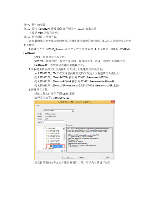
USER:用来保存工程文件;SYSTEM:用来存放一些官方提供的一些内核文件,以及一些常用的模块文件;HARDWARE:存放和硬件相关的模块文件;2.从我提供的程序代码里面拷贝文件到上面新建的文件夹里面;从1.STM32F4_LED工程文件里面拷贝资料文件到上面新建的文件夹里面:把1.STM32F4_LED--->SYSTEM拷贝到STM32_Demo---->SYSTEM;把1.STM32F4_LED--->HARDWAR拷贝到STM32_Demo---->HARDWARE;把1.STM32F4_LED--->USER--->main.c拷贝到STM32_Demo---->USER里面;3.新建项目工程:新建工程文件并保存到USAR里面;选择芯片如下:STM32F407ZG把文件里面的.c和.s文件添加到项目工程,可以先对其进行分组;最终出现的效果如下(组的名称随意命名):在文件里面还有很多.h文件,咱们要在工程里面知名路径;编译会出现问题,咱们需要添加1个宏定义;STM32F40_41xxx这样编译就没有问题了。
先让ST-Link和STM32开发板连接,并连接到计算机;咱们需要使用ST-Link下载,所以要配置如下:点击上图中“Settings”,进入如下界面:下载工程文件到STM32开发板:配置注意的几点:第四:项目工程的分析:USER:main.c;HARDWARE:led.c和led.h;相关LED灯的操作文件;SYSTEM:sys文件夹:startup_stm32f40_41xxx.s:官方提供的启动代码文件;stm32f4xx.h:官方提供的STM32F4系列芯片的头文件,类似reg51.h。
stm32f4xx使用FPU方法及简单测试

STM32F4系列FPU开启及测试◆要充分发挥STM32F4系列处理器FPU的数学性能,需要进行一些设置:1.编译控制选项。
在system_stm32f4XXX.c文件的system_init()函数里面添加如下代码(在keil5版本中不需要):/* FPU settings ------------------------------------------------------------*/#if (__FPU_PRESENT == 1) && (__FPU_USED == 1)SCB->CPACR |= ((3UL << 10*2)|(3UL << 11*2)); /* set CP10 and CP11 Full Access */#endif2.添加全局宏定义。
在工程选项(Project->Optionsfor target "XXXX")中的C/C++选项卡的Define 中加入如下的语句(用逗号隔开):__FPU_USED=1__FPU_PRESENT=1ARM_MATH_CM4__CC_ARMARM_MATH_MATRIX_CHECKARM_MATH_ROUNDING3.keil中开启FPU。
在工程选项的“Target”选项卡里的“Code Generation”下的“Floating Point Hardware”下拉菜单中选择“Use FPU”(keil5以上版本可能为“Single Precision”)。
4.添加官方DSP库。
在工程文件中添加arm_cortexM4lf_math.lib库文件(位于\Libraries\CMSIS\Lib\ARM中),库提供浮点数的各种基本运算函数,如以_f32结尾的运算函数。
5.包含头文件。
在需要使用浮点运算的文件中#include<arm_math.h>。
STM32F4的FPU性能的设置及要点

STM32F4的FPU性能的设置及要点除了网上的教程外,还要特别注意,当运算中有浮点的数字时要把,数字后面加上一个f。
例如表达式中有4.321参与运算。
当你不在4.321后加f时,stm32F405的片子不知道把他当做单精度float用FPU来运算,,默认可能是当做double来运算(我不确定),运算速度还是很慢。
切记所有浮点数字后面加上f,,,,有时候keil会提示warning:#1035-D:single-precision operand implicitly converted to double-precision 这句话的意思就是单精度运算隐式转换成了双精度运算了。
这个时候就要在单精度数字后面加个fkeilmdk的设置中完整的define是USE_STDPERIPH_DRIVER,STM32F4XX,__FPU_PRESENT=1,__FPU_USED =1,ARM_MATH_CM4,__CC_ARM要在MDK中有个选项设置usr FPUSTM32F4之FPU性能的充分发挥-设置要点浮点运算一直是定点CPU的难题,比如一个简单的1.1+1.1,定点CPU必须要按照IEEE-754标准的算法来完成运算,对于8位单片机来说已经完全是噩梦,对32为单片机来说也不会有多大改善。
虽然将浮点数进行Q化处理能充分发挥32位单片机的运算性能,但是精度受到限制而不会太高。
对于有FPU(浮点运算单元)的单片机或者CPU来说,浮点加法只是几条指令的事情。
现在又FPU或者硬件浮点运算能力的主要有高端DSP(比如TI F28335/C6000/DM6XX/OMAP等),通用CPU(X87数学协处理器)和高级的ARM+DSP 处理器等。
STM32-F4属于Cortex-M4F构架,这和M0、M3的最大不同就是多了一个F-float,即支持浮点指令集,因此在处理数学运算时能比M0/M3高出数十倍甚至上百倍的性能,但是要充分发挥FPU的数学性能,还需要一些小小的设置:1.编译控制选项:虽然STM32F4XX固件库的例程之system_stm32f4XXX.c文件中添加了对应的代码,但给用户评估使用的STM32F4-Discovery例程中却没有,因此MDK4.23编。
stm32f4 flash读写例程
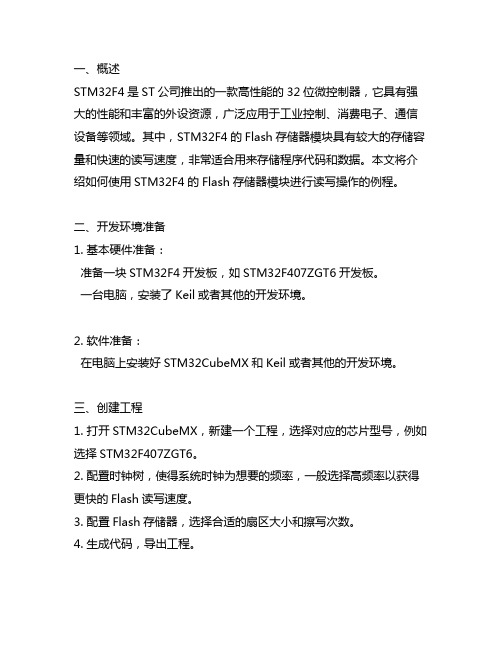
一、概述STM32F4是ST公司推出的一款高性能的32位微控制器,它具有强大的性能和丰富的外设资源,广泛应用于工业控制、消费电子、通信设备等领域。
其中,STM32F4的Flash存储器模块具有较大的存储容量和快速的读写速度,非常适合用来存储程序代码和数据。
本文将介绍如何使用STM32F4的Flash存储器模块进行读写操作的例程。
二、开发环境准备1. 基本硬件准备:准备一块STM32F4开发板,如STM32F407ZGT6开发板。
一台电脑,安装了Keil或者其他的开发环境。
2. 软件准备:在电脑上安装好STM32CubeMX和Keil或者其他的开发环境。
三、创建工程1. 打开STM32CubeMX,新建一个工程,选择对应的芯片型号,例如选择STM32F407ZGT6。
2. 配置时钟树,使得系统时钟为想要的频率,一般选择高频率以获得更快的Flash读写速度。
3. 配置Flash存储器,选择合适的扇区大小和擦写次数。
4. 生成代码,导出工程。
四、编写代码1. 在Keil或者其他的开发环境中打开刚刚生成的工程。
2. 找到Flash读写相关的API,一般在芯片提供的库函数中可以找到。
3. 根据需要编写Flash读写的代码,例如可以编写一个函数来实现向Flash写入数据的功能。
五、编译下载1. 编译代码,生成bin文件。
2. 将bin文件下载到STM32F4开发板中,可以使用ST-Link或者其他下载工具来完成。
六、调试运行1. 确保下载成功,重启开发板。
2. 进行调试,观察Flash读写是否正常。
七、注意事项1. 在进行Flash写入操作时,一定要小心谨慎,避免对程序的正常运行造成影响。
2. 在进行Flash擦除操作时,务必注意擦除的范围,避免擦除了不该擦除的数据。
3. 在进行Flash读写操作时,需要留意Flash的特性和限制,以免造成不必要的麻烦。
八、总结本文介绍了如何在STM32F4开发板上使用Flash存储器进行读写操作的例程,从开发环境准备到代码编写再到调试运行都有详细的步骤说明,并给出了注意事项和总结。
STM32F4工程模板建立方法
STM32F4工程模板建立方法在Keil环境下建立STM32F4的工程模板可以按照以下步骤进行操作:1. 打开Keil软件,选择“Project”->“New µVision Project”命令,弹出新建项目对话框。
2. 在对话框中选择工程的保存路径和名称,点击“Save”保存。
3. 在“Create Project Folder”对话框中选择是否要在工程文件夹中创建子文件夹,选择“Yes”或“No”并点击“OK”完成创建。
4. 弹出新建文件对话框,选择需要添加到工程中的文件类型,例如C源文件或者汇编文件,点击“Save”保存。
5. 在“Options for Target”对话框中选择芯片型号和包装封装类型,并点击“OK”关闭对话框。
6. 在Keil主界面的工程文件窗口中右键单击“Source Group”文件夹,选择“Add Existing Files to Group 'Source Group'”命令,选择要添加到工程的源文件,并点击“Add”完成添加。
7. 右键单击“Include”文件夹,选择“Add Exist ing Files to Group 'Include'”命令,选择要添加到工程的头文件,并点击“Add”完成添加。
8. 在工程文件窗口中选择“Options for Target”->“C/C++”选项,在右侧的Edit框中添加需要进行编译的文件路径,在Options forTarget - C/C++窗口中点击“OK”完成路径设置。
9. 在工程文件窗口中选择“Options for Target”->“Output”选项,在右侧的Edit框中选择输出文件的路径和名称,点击“OK”完成路径设置。
10. 在Keil主界面的工具栏中点击“Build”按钮进行编译,编译成功后会生成目标文件和可执行文件。
注意事项:1.在建立工程模板时,需要根据实际的芯片型号和芯片封装类型进行设置,确保编译器和调试工具能够正确地识别和支持所选的硬件。
STM32工程建立(F4系列)
使用MDK(Keil)建立一个STM32工程模板的流程如图所示:一.获取ST库源码。
到ST公司的官网进行查找并下载,如图所示:1.新建工程文件夹——《STM32工程模板》。
首先,新建工程文件夹《STM32工程模板》,然后再在该文件夹下新建6个文件夹,分别:《Doc》、《BSP 》、《Listing》、《Output》、《Project》和《User》。
其中,2.《Doc》用于存放各种说明文档;《BSP 》用于存放各种库文件;《Listing》用于存放编译时产生的中间文件;《Output》用于存放生成的下载所需的文件;《Project》用于存放工程文件;《User》用于存放用户文件,即我们自己编写的各种源文件。
具体情况如下图所示:具体步骤,以KEIL5 MDK5.18中建立STM32F417工程为例:二.STM32工程建立(F4系列)2016年4月13日16:57将下载的stm32f4_dsp_stdperiph_lib_zip 压缩包中的文件复制到工程模板文件夹下的STM32F4XX_StdPeriph_Driver 文件夹。
如下图:1)将stm32f4_dsp_stdperiph_lib\STM32F4xx_DSP_StdPeriph_Lib_V1.6.1\Libraries\CMSIS\Include 文件夹中对应的core_cm 文件复制到工程模板文件夹下的CMSIS文件夹。
具体操作情况如下图:2)向建立的工程文件夹中添加库文件。
3.将stm32f4_dsp_stdperiph_lib\STM32F4xx_DSP_StdPeriph_Lib_V1.6.1\Libraries\CMSIS\Device\ST\STM32F4xx\Include 文件夹中文件复制到工程模板文件夹下的CMSIS 文件夹。
具体操作情况如下图:3)将stm32f4_dsp_stdperiph_lib\STM32F4xx_DSP_StdPeriph_Lib_V1.6.1\Libraries\CMSIS\Device\ST\STM32F4xx\Source\Templates\arm 文件夹中对应芯片的startup 文件复制到工程模板文件夹下的CMSIS 文件夹。
第1讲STM32F4体系结构
第1讲STM32F4体系结构STM32F4系列是意法半导体公司(ST)推出的一款基于ARM Cortex-M4内核的32位微控制器系列。
它由多个不同的型号组成,每个型号都具有不同的特性和功能,以满足不同应用领域的需求。
本文将主要介绍STM32F4系列的体系结构。
STM32F4系列的核心是ARM Cortex-M4内核。
Cortex-M4是ARM最先进的32位处理器内核之一、它具有高性能、低功耗和丰富的外设集成特性。
Cortex-M4内核支持ARM Thumb-2指令集,能够提供高效的代码密度和高性能的处理能力。
它还支持浮点运算单元(FPU),可以实现高性能的信号处理和图像处理算法。
STM32F4系列微控制器的主频通常可以达到180MHz,具有丰富的存储器和外设资源。
它包含多个独立的时钟域,可以灵活地配置系统时钟,以满足不同应用的需求。
此外,STM32F4系列还提供了多个不同的电源管理模式,以实现低功耗运行和快速唤醒功能。
STM32F4系列具有丰富的外设资源,包括多个通用输入/输出端口(GPIO)、万能同步/异步收发器(USART)、通用同步/异步收发器(UART)、带有DMA控制器的直接存储器访问(DMA)、通用定时器(TIM)、高级定时器(TIM)、外部中断控制器(EXTI)等。
同时,STM32F4系列还具有多个模拟外设,如模数转换器(ADC)、数字模拟转换器(DAC)和温度传感器接口等。
除了丰富的外设资源,STM32F4系列还提供了多个与外设接口的总线,如现场可编程门阵列(FPGA)通信接口、SPI接口、I2C接口和USB接口等。
这些接口可以使STM32F4系列与其他硬件组件进行通信,实现更丰富的功能。
总之,STM32F4系列是一款强大的32位微控制器系列,具有高性能、低功耗和丰富的外设资源。
它适用于许多应用领域,如消费电子、嵌入式系统、工业自动化等。
无论是对于初学者还是专业开发者,STM32F4系列都是一个非常有价值的选择。
MDK5新建工程MDK5使用技巧STM32F4在线调试
MDK5新建⼯程MDK5使⽤技巧STM32F4在线调试建⽴相关⽂件夹如图所⽰FWLIB放官⽅固件库⽂件,HARDWARE放⾃⼰编写的.C,.H⽂件,USER放主函数⽂件,⼯程,启动⽂件等。
1,⾸先,打开 MDK(以下将 MDK5 简称为 MDK)软件。
然后点击 Project---New uVision Project ,然后保存在USER⽂件夹下,⼯程名⾃取。
2,选择 STMicroelectronics--STM32F4 Series--STM32F407--STM32F407ZGT6(如果使⽤的是其他系列的芯⽚,选择相应的型号就可以了,特别注意:⼀定要安装对应的器件 pack才会显⽰这些内容哦!!)。
3,点击 OK, MDK 会弹出 Manage Run-Time Environment 对话框。
这是 MDK5 新增的⼀个功能,在这个界⾯,我们可以添加⾃⼰需要的组件,从⽽⽅便构建开发环境,不过这⾥我们不做介绍。
所以在图 3.2.4 所⽰界⾯,我们直接点击 Cancel,即可。
得到如图所⽰界⾯:4,到这⾥,我们还只是建了⼀个框架,还需要添加启动代码,以及.c ⽂件等。
这⾥我们先介绍⼀下启动代码:启动代码是⼀段和硬件相关的汇编代码。
是必不可少的!这代码主要作⽤如下:1、堆栈(SP)的初始化;2、初始化程序计数器(PC);3、设置向量表异常事件的⼊⼝地址;4、调⽤ main 函数。
感兴趣的朋友可以⾃⼰去分析这部分代码。
ST 公司为 STM32F40x 和 STM32F41x 系列的 STM32F4 提供了⼀个共同的启动⽂件,名字为: startup_stm32f40_41xxx.s。
我们开发板使⽤的是 STM32F407ZGT6,属于 STM32F40x 系列⾥⾯的,所以直接使 startup_stm32f40_41xxx.s 这个启动⽂件即可。
不过这个启动⽂件,我们做了⼀点点修改,具体是 Reset_Handler 函数,该函数修改后代码如下:Reset_Handler PROCEXPORT Reset_Handler [WEAK];IMPORT SystemInit ;寄存器代码,不需要在这⾥调⽤ SystemInit 函数,;故屏蔽掉,库函数版本代码,可以留下;不过需要在外部实现 SystemInit 函数,否则会报错.IMPORT __mainLDR R0, =0xE000ED88 ;使能浮点运算 CP10,CP11LDR R1,[R0]ORR R1,R1,#(0xF << 20)STR R1,[R0];LDR R0, =SystemInit ;寄存器代码,未⽤到,屏蔽;BLX R0 ;寄存器代码,未⽤到,屏蔽LDR R0, =__mainBX R0ENDP这段代码,我们主要加⼊了开启 STM32F4 硬件 FPU 的代码,以使能 STM32F4 的浮点运算单元。
- 1、下载文档前请自行甄别文档内容的完整性,平台不提供额外的编辑、内容补充、找答案等附加服务。
- 2、"仅部分预览"的文档,不可在线预览部分如存在完整性等问题,可反馈申请退款(可完整预览的文档不适用该条件!)。
- 3、如文档侵犯您的权益,请联系客服反馈,我们会尽快为您处理(人工客服工作时间:9:00-18:30)。
使用MDK(Keil)建立一个STM32工程模板的流程如图所示:
一.获取ST库源码。
到ST公司的官网进行查找并下载,如图所示:
1.新建工程文件夹——《STM32工程模板》。
首先,新建工程文件夹《STM32工程模板》,然后再在该文件夹下新建6个文件夹,分
别:《Doc》、《BSP 》、《Listing》、《Output》、《Project》和《User》。
其中,
2.《Doc》用于存放各种说明文档;
《BSP 》用于存放各种库文件;
《Listing》用于存放编译时产生的中间文件;
《Output》用于存放生成的下载所需的文件;
《Project》用于存放工程文件;
《User》用于存放用户文件,即我们自己编写的各种源文件。
具体情况如下图所示:
具体步骤,以KEIL5 MDK5.18中建立STM32F417工程为例:
二.STM32工程建立(F4系列)
2016年4月13日16:57
将下载的stm32f4_dsp_stdperiph_lib_zip 压缩包中的文件复制到工程模板文件
夹下的STM32F4XX_StdPeriph_Driver 文件夹。
如下图:
1)将stm32f4_dsp_stdperiph_lib\STM32F4xx_DSP_StdPeriph_Lib_V1.6.1
\Libraries\CMSIS\Include 文件夹中对应的core_cm 文件复制到工程模板文件夹下的CMSIS文件夹。
具体操作情况如下图:
2)向建立的工程文件夹中添加库文件。
3.
将stm32f4_dsp_stdperiph_lib\STM32F4xx_DSP_StdPeriph_Lib_V1.6.1
\Libraries\CMSIS\Device\ST\STM32F4xx\Include 文件夹中文件复制到工程模板文件夹下的CMSIS 文件夹。
具体操作情况如下图:
3)将stm32f4_dsp_stdperiph_lib\STM32F4xx_DSP_StdPeriph_Lib_V1.6.1
\Libraries\CMSIS\Device\ST\STM32F4xx\Source\Templates\arm 文件夹中对应芯片的startup 文件复制到工程模板文件夹下的CMSIS 文件夹。
具体操作情况如下图:
4)将库文件中Project文件夹下的相关文件复制到工程模板文件夹下的User文件
夹中。
具体操作情况如下图:
5)
首先得选择CPU,这个在新建工程时,会有一个选择芯片的界面,选择工程所
需要的芯片型号。
具体操作情况如下图:
1)进入"Manage Project Items",更改工程名并为工程添加项目组(Add group
to project)。
具体操作情况如下图:
2)分别向各个项目组中添加我们刚刚从库中复制过来的文件文件(Add files
to group)。
具体操作情况如下图:
3)使用MDK(Keil)新建工程模板。
4.
to group)。
具体操作情况如下图:
配置Target选项卡。
具体操作情况如下图:
1)(备注:microlib 是缺省C 库的备选库。
microlib中和标准C库之间的主要区别是:
microlib中是专为深度嵌入式应用。
microlib中被优化使用比使用ARM标准库更少的代码和数据存储器。
microlib中已经设计没有操作系统的工作,但是这并不妨碍它被与任何操作系统或RTOS如Keil RTX一起使用。
microlib中不包含任何文件I/ O或宽字符支持。
由于microlib中进行了优化,以尽量减少代码大小,一些功能将会比ARM编译工具提供了标准C库函数更慢执行。
microlib中双方和ARM标准库都包含在Keil MDK -ARM。
)
配置Output选项卡。
具体操作情况如下图:
2)工程配置。
5.
3)
配置Listing选项卡。
具体操作情况如下图:
4)
配置C/C++选项卡。
具体操作情况如下图:
5)
配置Debug选项卡。
具体操作情况如下图:
6)
配置Utilities选项卡。
具体操作情况如下图:。