电子信息工程本科毕业中英文翻译
电子信息工程专业英语 课文翻译 Unit 12 译文
Unit 12 生物识别技术Unit 12-1第一部分:指纹识别在所有的生物技术中,指纹识别是最早期的一种技术。
我们知道,每个人都有自己独特的、不可变更的指纹。
指纹是由手指表皮上的一系列峰谷组成的。
指纹的独特性是由这些峰谷的形状以及指纹的细节点所决定的。
指纹的细节点是指纹局部凸起处的一些特性,这些特性出现在凸起的分叉处或是凸起的截止处。
指纹匹配技术可以被分为两类:基于细节的指纹匹配技术和基于相关性的指纹匹配技术。
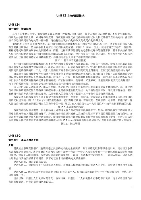
基于细节的指纹匹配首先要找出细节点,然后在手指上对应出与它们相关的位置,如图12.1所示。
但是,使用这种方法存在一些困难。
要精确地提取指纹的细节点是很困难的。
而且,这种方法不能很好地考虑指纹峰谷的整体形状。
基于相关性的指纹匹配技术可以解决部分基于细节的指纹匹配方法存在的问题,但它也存在一些自身的缺陷。
基于相关性的匹配技术需要给出已注册过的特征点的精确位置,并且该方法会受图像平移和旋转的影响。
图12.1 基于细节的指纹匹配基于细节的指纹匹配技术在匹配不同大小的细节模型时(未注册过的)会存在一些问题。
指纹上局部的凸起结构不能完全由指纹细节实现特征化。
我们可以尝试另一种表达指纹的方法,它可以获得更多的指纹局部信息并且得到固定长度的指纹编码。
于是,我们只需要计算两个指纹编码之间的欧几里得距离,匹配过程有望变得相对简单。
研发对于指纹图像中噪声更稳健并能实时提供更高精度的算法是重要的。
商用指纹(身份)认证系统对给定的错误接受率要求具有很低的错误拒绝率。
在这点上,任何一项简单的技术都很难实现。
我们可以从不同的匹配技术中汇总多个证据从而提高系统的总体精确度。
在实际应用中,传感器、采集系统、性能随时间的变化是关键因素。
为了评价系统性能,我们有必要对少数使用者在一段时间内进行现场试验。
每天我们可以从法医鉴定、出入口控制、驾驶证登记等多个方面的应用中采集并保存大量的指纹。
基于指纹的自动识别系统需要把输入的指纹与数据库中大量的指纹进行匹配验证。
电子信息工程专业课程翻译中英文对照表
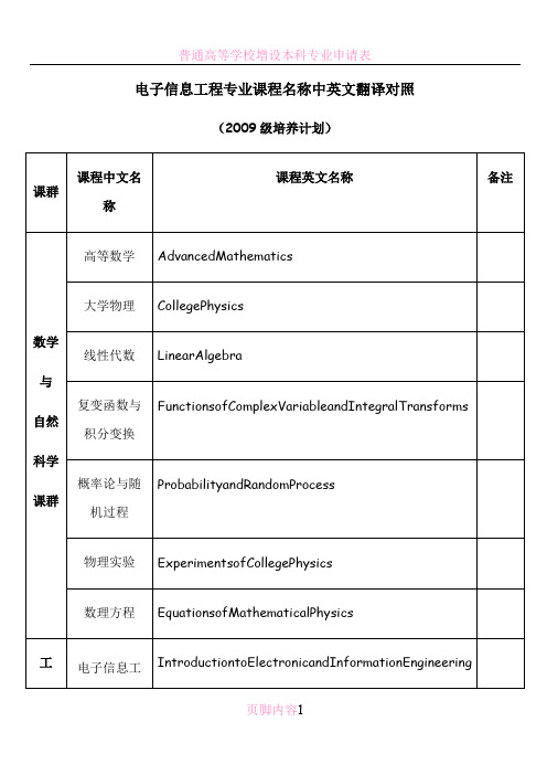
(2009级培养计划)
课群
课程中文名称
课程英文名称
备注
数学
与
自然
科学
课群
高等数学
AdvancedMathematics
大学物理
CollegePhysics
线性代数
LinearAlgeቤተ መጻሕፍቲ ባይዱra
复变函数与积分变换
FunctionsofComplexVariableandIntegralTransforms
光纤通信技术(双语)
OpticalFiberCommunicationTechnology
实践环节翻译
实践环节翻译
军训及新生入学教育
MilitarySkillsTrainingandFreshmenEducation
模拟电子技术课程设计
CoursePracticeforAnalogElectronic
信息论基础
FundamentalsofInformationTheory
信号与线性系统
SignalsandLinearSystems
微机原理与接口技术
MicrocomputerPrinciplesandInterfaceTechnology
人
文
社
会
科
学
课
群
马克思主义基本原理
FundamentalsofMarxism
生产实习
ProductivePractice
毕业设计(论文)
GraduationThesis
现代通信技术
ModernCommunicationsTechnology
DSP原理及应用
PrinciplesandApplicationsofDSP
电子信息工程专业英语英译汉翻译
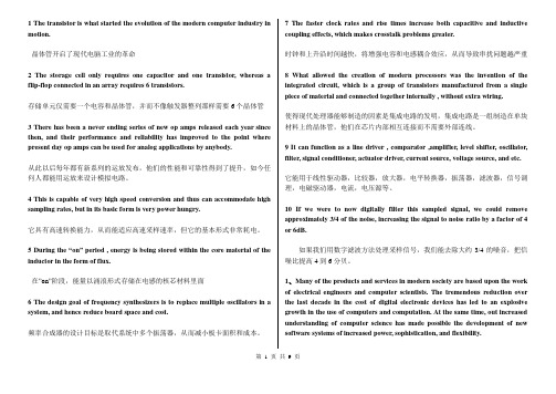
1 The transistor is what started the evolution of the modern computer industry in motion.晶体管开启了现代电脑工业的革命2 The storage cell only requires one capacitor and one transistor, whereas a flip-flop connected in an array requires 6 transistors.存储单元仅需要一个电容和晶体管,并而不像触发器整列那样需要6个晶体管3 There has been a never ending series of new op amps released each year since then, and their performance and reliability has improved to the point where present day op amps can be used for analog applications by anybody.从此以后每年都有新系列的运放发布,他们的性能和可靠性得到了提升,如今任何人都能用运放来设计模拟电路。
4 This is capable of very high speed conversion and thus can accommodate high sampling rates, but in its basic form is very power hungry.它具有高速转换能力,从而能适应高速采样速率,但它的基本形式非常耗电。
5 During the “on” period , energy is being stored within the core material of the inductor in the form of flux.在”on”阶段,能量以涌浪形式存储在电感的核芯材料里面6 The design goal of frequency synthesizers is to replace multiple oscillators in a system, and hence reduce board space and cost.频率合成器的设计目标是取代系统中多个振荡器,从而减小板卡面积和成本。
电子信息工程毕业设计外文翻译

xx大学毕业设计外文翻译系别职业技术教育学院专业电子信息工程班级电子Z091 学号 x姓名 x指导教师 x2013年5月16日MM420 inverter energy-saving measures in the water supply system-Nanjing Hangda Yihang Technology Co., Ltd.Because the frequency conversion velocity modulation does not need to construct the tradition for the aqueous system for the aqueous system top digit water tank, the water tank, avoided two times polluting and reducing the construction investment, moreover designed reasonably can achieve the good energy conservation effect.In gives in the aqueous system, the constant speed pump only then in its highly effective section movement can guarantee the system normal work also does not have the energy dissipation.In the design, (this time current capacity is generally biggest by the pipe network most unfavorable situation, must lift is also biggest) takes the choice water pump unit the main basis, but when the pipe network current capacity reduces, the energy waste is inevitable, when also possibly creates the low current capacity in pipeline overpressure question.The water pump basis system current capacity real-time change realization stepless speed regulation movement, is solves above problem well, achieves one of energy conservation goal ways.The water pump velocity modulation may through the very many way realization, in which frequency conversion velocity modulation be the present ideal one kind.The frequency conversion velocity modulation is through will give on the aqueous system pipe network the pressure transmitter to carry on the sampling to the pipe network hydraulic pressure, transforms the pressure signal into the electrical signal, and delivers to the PID regulator and the user establishment value of pressure it carries on the comparison and the operation, finally will transform for the frequency control signal delivers to the frequency changer.The frequency changer basis transmits frequency control signal adjustment water pump electrical machinery supply frequency, thus realizes adjusts the water pump the rotational speed.May divide into two kinds according to the customer in actual use request frequency conversion velocity modulation for the aqueous system: The live pressure variable gives the aqueous system for the aqueous system and the constant pressure variable.The live pressure variable establishes for the aqueous system pressure transmitter in the service pipe net terminal, the PID regulator setting value the service flood peakvalue which needs for the pipe network terminal user.The system causes the pipe network terminal hydraulic pressure maintenance through the automatic control to be constant, causes the pipeline characteristic curve and system static lifting is invariable, but the water pump water outlet pressure changes along with the volume of diversion change according to the pipeline characteristic curve, therefore theoretically realized “the system to need how many, the unit provided how many”, could not because the volume of diversion reduced has unnecessary static lifting, the energy conservation effect was satisfied.But this is only one kind of ideal situation, also in the system only has the frequency conversion pump alone to work.Because the frequency conversion equipment quite is expensive, large-scale often uses the frequency conversion pump and the constant speed pump parallel operation way water supply for the aqueous system.Presently establishes a frequency conversion pump and a power frequency pump and the combined transport behavior example by the system in.When the pipe network current capacity reduces, needs to lift reduces correspondingly, the frequency conversion pump may through the deceleration movement realization.But also must reduce correspondingly for guarantee parallel unit normal work power frequency pump lifting, this only can through increase the current capacity realization, thus creates the water volume the dropout, also possibly causes the power frequency pump to leave the highly effective section work, namely has not achieved the true energy conservation the goal.Meets has above situation, may take following measure to improve its energy conservation effect:①Gives the aqueous system regarding the small scale, may only suppose a frequency conversion pump, and causes the pump the highly effective area (its highly effective scope to move the time scope compared to power frequency pump to want as far as possible many including to appear the probability big operating point in a big way).②Uses the multi-Taiwan pump velocity modulation movement, certainly, quite is expensive as a result of the frequency conversion speeder price, should overall evaluation its economic agent decide.③When choice power frequency pump, should cause the system when the most disadvantageous spot work, the power frequency pump operating point approaches left side of as far as possible its highly effective area; If the most unfavorable situation appears the probability to be small, may enable it to deviate slightly the highlyeffective area, falls in the highly effective area left flank.Thus, when system lifting reduces, the power frequency pump still may in the highly effective area work.The constant pressure variable is located in the water pump unit water outlet for the aqueous system the pressure transmitter, is for the purpose of causing the water pump water outlet pressure maintenance to be constant, general hypothesis for most disadvantageous operating mode when the water pump water outlet needs the value of pressure.Still by a frequency conversion pump and a power frequency pump and combined transport behavior example.When the pipe network current capacity reduces, the frequency conversion pump through the deceleration movement, maintenance lifting invariable reduces the water discharge.Because the outlet pressure is invariable, the power frequency pumps out the water volume not to be able to change (i.e. movement operating mode invariably), still in highly effective area work, thus achieves the energy conservation goal.Needs to point out, the system needs when the current capacity changes small, the water pump water outlet pressure (still for the most unfavorable situation in system needs pressure) to be bigger than the pressure which the pipeline this time needs, thus still could cause static lifting to a certain extent the waste.Following two measures may improve its energy conservation effect:①Enlarges the pipe network suitably the caliber, causes the pipeline characteristic curve to hasten gently, but this can increase the pipe network the disposable investment, needs and the energy conservation effect makes the comprehensive economical comparison.②When choice power frequency pump causes each pump the operating point to fall as far as possible on the highly effective area.For aqueous system when water used trough (for example at night), in the system the water consumption is very small, even achieved the zero current capacity, is called “the micro current capacity”.In this case, if depends upon at the highly effective area great current capacity scope movement water pump maintains the system pressure, not only buckle water pump life, moreover the efficiency is low, cannot achieve the energy conservation the goal.Theoretically, the frequency conversion pump current capacity may approach in the highly effective scope in the zero, but in fact the water pump rotational speed not impossible unlimited to reduce, only depends on the frequency conversion pump to be competent the micro current capacity operating mode with difficulty toward the dealings.The actual project uses generally when the system additionally builds the small current capacity power frequency auxiliary pump,small current capacity facilities and so on frequency conversion auxiliary pump, barometric pressure pot maintain the micro current capacity the system pressure.To the different system micro current capacity question should the special details concrete analysis, and carries on the overall evaluation to the disposable investment and the long-term operating cost to be able to make the reasonable solution.In the frequency conversion velocity modulation for in the aqueous system design process, should choose the pump reasonably according to the service pipe net characteristic, achieved in satisfies the operation requirements under the premise, both saves the goal which the investment and conserves energy.MM420变频器在给水系统的几点节能措施-南京航大意航科技股份有限公司由于变频调速给水系统不需要建造传统给水系统的高位水箱、水塔,避免了二次污染并减少了土建投资,而且设计得合理能达到较好的节能效果。
CP2102中英文翻译

本科毕业设计(论文)外文翻译译文学生姓名:院(系):电子信息工程学院专业班级:电信0901指导教师:严正国完成日期:2013 年04 月02日CP2102USB转UART芯片数据手册CP2102 SINGLE-CHIP USB TO UART BRIDGE作者:CYGNAL单芯片USB数据传输到UART-- 综合USB收发器无需外部电阻要求-- 集成的时钟无需外部晶振体要求-- 综合1024-Byte EEPROM用于产品的供应商ID,ID,序列号,电源描述,版本号和产品描述字符串-- 片上电复位电路-- 片上电压调节器:3.3v电压输出-- 100%引脚和软件兼容与CP2101USB功能控制器-- USB规范2.0标准:(全速12 Mbps)-- USB暂停支持国家通过悬浮pins异步串行数据总线(UART)-- 所有的握手和调制解调器借口信号-- 数据格式支持- 数据bits:5,6,7和8- 停止bits:1,1.5和2- 校验:奇,偶,标记,空间,无校验-- 波特率:300 bps到1兆位-- 567字节的接受缓冲区;640字节的发送缓冲区-- 支持硬件或X-On/X-Off 握手-- Event字符支持-- 输电线路中断虚拟设备驱动程序COM口-- 使用现有的COM端口的PC应用-- 免版税发行许可证于Windows Vista / XP / 服务器2003 / 2000 / 1998SE-- 苹果OS-X / 0S-9-- LinuxUSB Express 直接驱动器支持-- 免版税发行许可证-- 于Windows Vista / XP / 服务器2003 / 2000-- 视窗CE 5.0 和4.2应用实例-- 传统设备的RS-232升级到USB-- 蜂巢式电话USB接口电缆-- PDA USB 接口电缆-- USB到RS-232 串行适配器电源电压-- 自供电:3.0 v到3.6 vUSB总线供电:4.0 v到5.25 v包装-- 无铅28-pin QFN (5 * 5mm)订购零件编号-- CP2102-GM温度范围:-40到+85摄氏度图1. 系统功能电路1.系统概述该CP2102是一个高度集成的USB-UART桥控制器提供了一个简单的解决方案更新RS-232设计,USB使用的组件和PCB空间最小,该CP2102包括USB2.0全速功能控制器,USB收发器,振荡器和带有全部的调制解调器控制信号的异步串行数据总线(UART),全部功能集成在一个5 * 5 mm MIP-28封装的IC中,无需其他的外部USB元件,片内EEPROM可用于由原始设备制造商自定义USB 供应商代码、产品代码、产品描述文字、功率标牌、版本号和元件序列号等数据的存储空间。
电子信息工程专业毕业论文外文翻译中英文对照翻译

本科毕业设计(论文)中英文对照翻译院(系部)电气工程与自动化专业名称电子信息工程年级班级 04级7班学生姓名指导老师Infrared Remote Control SystemAbstractRed outside data correspondence the technique be currently within the scope of world drive extensive usage of a kind of wireless conjunction technique,drive numerous hardware and software platform support. Red outside the transceiver product have cost low, small scaled turn, the baud rate be quick, point to point SSL, be free from electromagnetism thousand Raos etc.characteristics, can realization information at dissimilarity of the product fast, convenience, safely exchange and transmission, at short distance wireless deliver aspect to own very obvious of advantage.Along with red outside the data deliver a technique more and more mature, the cost descend, red outside the transceiver necessarily will get at the short distance communication realm more extensive of application.The purpose that design this system is transmit cu stomer’s operation information with infrared rays for transmit media, then demodulate original signal with receive circuit. It use coding chip to modulate signal and use decoding chip to demodulate signal. The coding chip is PT2262 and decoding chip is PT2272. Both chips are made in Taiwan. Main work principle is that we provide to input the information for the PT2262 with coding keyboard. The input information was coded by PT2262 and loading to high frequent load wave whose frequent is 38 kHz, then modulate infrared transmit dioxide and radiate space outside when it attian enough power. The receive circuit receive the signal and demodulate original information. The original signal was decoded by PT2272, so as to drive some circuit to accomplishcustomer’s o peration demand.Keywords:Infrare dray;Code;Decoding;LM386;Redoutside transceiver1 Introduction1.1 research the background and significanceInfrared Data Communication Technology is the world wide use of a wireless connection technology, by the many hardware and software platforms supported. Is a data through electrical pulses and infrared optical pulse switch between the wireless data transceiver technology.Infrared transceiver products with low cost, small, fast transmission rate, the point-to-point transmission security, not subject to electromagnetic interference and other characteristics that can be achieved between the different products, rapid, convenient and safe exchange and transmission, In short distance wireless transmission have a very distinct advantage.Infrared transceiver products in the portable product of a great role. At present, the world's 150 million piece of equipment used infrared technology in electronic products and industrial equipment. medical equipment and other fields widely used. For example, 95% of the notebook computers on the installation of infrared transceiver interface the majority of the cell phone is also the allocation of infrared transceiver interface. With the exchange of quantitative data, infrared data communications will enable cell phone data transmission more convenient. With infrareddata transmission technology matures, perfect, low costs, Infrared Transceiver in short distance communications will be more widely applied.This chapter first describes the infrared transceiver IC design issues to the background and significance. then briefed the infrared data communications technology features and applications, and infrared transceiver product characteristics, domestic and international situation and development trend of the last under infrared remote transceiver system in practical application to establish a task of design orientation.1.2 Infrared Remote ControlTransceiver SystemInfrared remote control system is divided into single-channel and multi-channel remote control. Only a command signal transmission channel, called single-channel remote control system; with more than two instructions signal transmission channel known as a multi-channel remote control system. Relatively simple single-channel remote control, in general, only a launcher directive Key receivers and only one circuit implementation. While in the receiving circuit to add more stable memory circuits that can be activated commands to launch a number of key, so that the receiver circuit multistable memory circuit repeatedly to change the state, to realize many of the functional control, But such a state of change is the order. If we are to achieve an arbitrary control, resort to the use of multi-channel remote control system. Multi-channel remote control can be realized by the object of arbitrary multi-function remote control. As for the choice of several routes and what control methods, according to the actual situation (such as object, operational requirements and costaccounting, etc.) to decide. General infrared remote transceiver system by infrared remote control transmitter signal coding, infrared remote control signal receivers and decoders (or decoder chip MCU) and the external circuit consisting of three parts. Signal transmitter remote control code used to generate pulses of infrared emission-driven output infrared remote control signal, receiver completion of the remote control signal amplification and detection, plastic and demodulation encoding pulse. Infrared remote control coded pulse is going to obtain a continuous serial binary code, and for most of the infrared transceiver system, This serial code as micro-controller of the remote control input signals from the internal CPU completion of the remote control instruction decoder, on the other infrared remote control transceivers, the designers of electronic products, The internal micro-controller of the remote control decoder directive is not accessible. Therefore, people are using infrared encoder / decoder chip and microcontroller developed various generic infrared remote transceiver system, In various equipment infrared signals between the transceiver.Remote transceiver system generally transmitters and receivers is composed of two parts. Launchers from the general direction keys, coded instructions circuit modulation circuit, driving circuit, firing circuit of several parts. When pressed a key, the directive coding circuit, in the corresponding instructions encoded signal, the encoder signal to the carrier modulation, Driven by the power amplifier circuit after circuit fired from the field after firing instructions coded modulation signals. General receiver by the receiving circuit, the amplifier circuit, demodulation circuits, instruction decoder circuit, driving circuit, circuitimplementation of several parts. Receiving Circuit will launch vehicles have been coded modulation signal receiving instructions from, and to enlarge evacuation demodulation circuit. Demodulation circuit will have the coding modulation signal demodulation, namely, reduction of signal coding. The instruction decoder to the encoder signal decoding, Driven by the final circuit to drive the implementation of various instructions circuit to control the operation.1.3 infrared remote control transceiver product profiles1.3.1 infrared remote control transceiver product structure and typeCurrently infrared transceiver in accordance with the mode of transmission rate and can be divided into four categories : Serial mode, the highest rate of 115.2 Kbps; medium-speed model : the highest rate of 0.567 Mbps and 1.152Mbps; High-speed mode : The maximum rate of 16 Mbps.Also according to the size chip power consumption can be divided into low-power consumption and standard two categories, low-power type normally used 3 V power supply, transmission distance closer to about 0 - 30cm, which is commonly used standard 5V power supply, transmission distance away at least 1m above.1.3.2 infrared remote control transmitters of the status quo at home and abroadInfrared communication technology in the development stage and there are several infrared communication standards, between different standards for infrared equipment can not infrared communication. To have all the infrared equipment to interoperability in 1993 by more than 20 large manufacturers initiated the establishment of an Infrared Data Association (IRDA)unified the infrared communication standards , which is currently widely used in infrared data communication protocols and standards, also known as the IRDA standard.Since 1993 IRDA since the establishment of the Infrared Data Association members have developed to more than 150. IRDA standards of the industry has been widely recognized and supported. Has been developed with the infrared communications equipment have been as many as 100 species. IR module, installed capacity has reached 150 million sets. Although there is also a short distance wireless Bluetooth technology, But in infrared communication technology low cost and broad compatibility advantages, Infrared data communication in the future will still be a very long time inherent short-range wireless data communications fields play an important role.1.3.3 Infrared Transceiver product development trendIn various infrared transceiver products, although the transmission rate, transmission distance and other characteristics, But infrared transceiver products has been towards improving the transmission rate, increase the transmission distance and lower power consumption, expanding launch reception angle of development. In particular, as the technology development and maturity, the means of transmission is moving in the direction of point-to-multipoint. Therefore infrared remote control transceiver products have broader prospects for development.2 Infrared communication of knowledge2.1 infrared ray foundation knowledge2.1.1 infrared outlinedInfrared is actually a kind of electromagnetic wave. From theanalysis of various natural component of the electromagnetic wave reflected spectrum is :-ray, x-ray, ultraviolet, visible, infrared, microwave and radio wave. From the viewpoint of form, and they did not seem to, but if the wavelength in descending order, and we will find him all the only visible light spectrum of the entire 0.38 μm - 0.76μm so long little area, and adjacent to the visible light and infrared (including the far infrared, mid-infrared and near infrared foreign) accounts for the spectrum of 0.76 μm - 1000μm of a major. Which micron wavelength range also includes UV, visible, near infrared, mid-infrared and far-infrared, microwave.From the above analysis shows that infrared is a very rich spectrum resources, it currently has in production, life, military, medical, and other aspects have been widely used, such as infrared heating, medical infrared, infrared communication, infrared camera, infrared remote control, and so on. Infrared remote control is the many applications of infrared part of the current household appliances widely used in TV remote control, VCR remote control, VCD remote control, high-fidelity audio remote control, are used infra-red remote control, It allows the control of these appliances have become very easy.2.1.2 infrared propertiesInfrared lies between visible light and microwave a wave, it is with certain clinical characteristics of the wave. In the near-infrared, visible light and its adjacent, it is visible in certain characteristics, such as straight-line transmission, reflection, refraction, scattering, diffraction, can be certain objects and can be absorbed through the lens of their focusing. In the far-infrared region, owing to its neighboring microwave, it hassome characteristics of microwave, If a strong penetrating power and can run through some opaque substances. Since in any object, natural profession, regardless of whether its own luminescence (referring to visible light), as long as the temperature is above absolute zero (-273 ° C), moment will be kept around to infrared radiation. Only higher temperature of objects strong infrared radiation, low-temperature objects infrared radiation weaker. Therefore infrared feature is the greatest common in nature, it is called thermal radiation called thermal radiation. Infrared cameras, infrared night market pyroelectric infrared detectors and some other missiles aiming at is the use of this characteristic of infrared work.Infrared and visible light compared to another characteristic of a variety of colors. As the longest wavelength of visible light is a wavelength of the shortest times (780 nm-380 nm), So is called an octave. And infrared wavelength is the longest shortest wavelength of a times, and the longest wavelength infrared is the shortest wavelength of 10 times, that is, 10 octave. Therefore, if visible light can be expressed as seven colors, infrared may performance 70 colors, showing the rich colors. Infrared smoke through the good performance, which is also one of its features.Because not visible to the infrared, it has little effect on the environment. By the wave infrared rays than the long wavelength radio waves, infrared remote control will not affect the nearby radio equipment. Another wavelength of less than 1.5μm near infrared light, transparent atmosphere in the visible light transmission characteristics much better than, because it close to the visible edge of the red light, linear transmission, reflection,refraction and absorption material and the physical characteristics very similar to visible light. Therefore, it can be used with similar visible focusing lens and other optical devices. Because infrared remote control is not as remote as the radio through the barrier to control the object's ability to control, so in the design of household appliances infra-red remote control, wireless remote control as unnecessary, each set (transmitters and receivers) have different frequency or remote coding (Otherwise, wall will control or interference with neighbors household appliances), all similar products in the infrared remote control, The same can control the frequency or coding, and no remote control signal "drop." This universal infrared remote control provides a great convenience. Infrared to visible light, is very subtle and confidentiality, therefore, the security, Alert and other security devices have been widely used. Infrared remote control is simple in structure and easy, low-cost, anti-interference capability, high reliability are a number of advantages, is a close-up remote control, especially in indoor remote control optimized manner. 2.1.3 infrared diode characteristicsInfrared is not visible, people here are not aware of. Electronic technology is used infrared light emitting diode (also known as the IR emission diode) to generate infrared. Infrared remote control transceiver is using near-infrared transmission control instructions 0.76μm wavelength of ~ 1. 5μm. Near-infrared remote control as a light source, because there infrared light emitting diodes and infrared receiving device (photodiode. Transistor and PV) and the luminescence peak wavelength of lightby the general 0.8μm ~ 0. 94μm. in the near-infrared band, both of the spectrum is the coincidence to a good match, access to higher transmission efficiency and higher reliability. Commonly used infrared diode, and its shape is similar LED light emitting diodes, Its basic circuit shown in figure 2 -2. The triode plans for the switch, when the base added a driving signal, Transistor saturated conduction infrared LED D is also Wizard Link, issued infrared (near infrared about 0.93 μm). D. The pressure drop of about 1.4 V and the current general for 10-20mA. To adapt to the working voltage of the D loop resistance often as a series of infrared diode current limit resistance.When the circuit diagram of the infrared emission control corresponding to the controlled device, the control of the distance and D is proportional to the transmitting power. In order to increase the distance of infrared control, infrared diode D should work on the pulse state that work is the lifeblood of current. Because pulse light (optical modulation) the effective transmission distance and pulse is proportional to the peak current, only maximize peak current Ip, will increase the infrared distance. Ip increase is a way to reduce the pulse duty cycle, that is compressed pulse width τ some TV infrared remote control, its infrared luminescence of the pulse duty cycle of about 1/4-1/3; Some electrical products infrared remote control, its duty cycle of 1 / 10. Decreasing pulse duty cycle also enable low-power infrared LED distance of the greatly increased. Common infrared light emitting diodes, power is divided into small power (1 mW - 10mW). Chinese power (20mW - 50mW) and power (50mW - 100mW more) three categories. Use different power infrared LED, the allocation shouldbe driven by the corresponding power control. Figure 2 -2 by the reflected infrared light-emitting diodes to make produce optical modulation, Drivers only need to add the control of a certain frequency pulse voltage.Infrared transmitter and receiver in the way the two kinds of straight, and the second is reflective. Luminescence pointed straight pipe and tube receiver placed in a relatively controlled and fired on the two ends, a certain distance away from the middle; Reflective means luminescent tube and pipe parallel with the receiving peacetime, without always receiving tube light, luminescence only in possession of the infrared light reflected from encountered, the receiving tube received from the reflected infrared before work.2.2 infrared communication basic tenets2.2.1 infrared communication PrincipleCommunication is the use of infrared wavelength of 900 nm-infrared waves from 1000 to serve as an information carrier, through infrared technology between the two close communication and confidentiality of information transmitted. Infrared communication system structure include : part launcher, channel, the receiver part.Launcher source letter issued after the binary signal from the high-frequency modulated infrared LED sent, receiving device regard the reception of high-frequency signals from the infrared receiver tube after receiving further demodulation photoelectric conversion of the original information of a mass communication lose way. Afterwards the former Information received after receivingpart of the drive circuit connected to the expected completion of the various functions. To which the modulation coding style pulse width modulation (by changing the pulse width modulated signal PWM) and pulse modulation time (through change the pulse train interval time between the modulation signal PPM) two.2.2.2 infrared communication system elements(1) Launches : Currently there is a infrared wireless digital communications system sources of information including voice, data, images. Its methods of work for the launch of the receiver can be divided into different layout LOS way (Light-of-Sight , intracardiac way), diffuse (diffuse) mode. LOS way directional, it has good channel characteristics such advantages, but the existence of a "shadow" effect. difficult to achieve roaming function. Roaming means the main features of non-directional, and easy to implement roaming function, but its channel quality is better sometimes LOS way. Transmission of signals required for a few of (the sampling was quantified), the general need for baseband modulation, transmission, modulation, sometimes signal source coding, the above-driven signals from photoelectric converter complete optical signal transmission. Infrared wireless digital communications system and its scope of work-for-fired power distribution, the quality of the communication. While using various methods to improve optical transmitter power, the other using spatial diversity, holographic films and so on so diffuse light for the launch of space optical power evenly distributed.(2) Channel : infrared wireless digital communication channel refers to the transmitters and receivers in the space between. Due to natural light and artificial light sources such as light signalsin the context of intervention, and the source - Electrical Equipment, The optical noise and disturbances, infrared wireless digital communications in some occasions, poor quality, At this point needed to channel coding. Infrared wireless communication system, the optical signal reflection, light scattering and background noise and interference effects, Infrared wireless digital channel presence multi-path interference and noise, This is to improve the quality and access for high-speed applications should be addressed. Infrared wireless digital communication channel often used by the major optical components, optical filter, condenser, their role is : plastic, filter, depending on the field transformation, the band division, the lens can be used as launch-ray focusing, the use of optical filters filter out stray light, the use of optical lenses to expand the field of view receiver, able to make use of optical components for the link frequency division multiplexing, etc.. Infrared wireless communication channel optical noise : the natural noise (sunlight) and anthropogenic interference (fluorescent lighting). can be modulated by the transmission technology such as filters and adding to be addressed.(3) receivers : Channel optical signal from the optical receiver partially photoelectric conversion, In order to remove noise and intersymbol interference and other functions. Infrared wireless digital communications system receiver include optical receiver parts and follow-up sampling, filtering, judgment, quantity, balanced and decoding part. Infrared wireless optical receiver often used amplifier, and called for large-bandwidth, high gain, low noise and low noise, frequency response and channelimpulse response matched. To be suppressed by low-frequency noise and human disturbance needs a band-pass filter. To obtain large optical receiver scope and instantaneous field of view, often using spherical optical lens.2.2.3 infrared communications featureWireless communications are a lot of ways, some using infrared communication with the following characteristics :• The high frequency, wave length, and fired the energy concentrated space propagation attenuation coefficient can ensure the effective signal transmission;• infrared is the invisible light, strong confidentiality and use it as an information carrier. device when there is no visual pollution, it does no harm to the human body;• dissemination without limitation, and there is no question of frequency interference with radio-wave pattern, not on the spectrum resources to the relevant authorities for the application and registration, easy to implement;• has a good point, when the transmission equipment and infrared receiver ports line up straight, deviation of not more than about 15 degrees when infrared devices running the best effect;• through infrared or not bypassed and objects, data transmission, optical path can not be blocked;• currently produce and receive infrared signals in the technology is relatively mature, components small size, low cost production of simple, easy to produce and modulation advantages.2.3 infrared communication code based on the knowledgeUsually, infrared remote control transmitters will signal (pulse binary code) modulation at 38 KHz carrier, After buffer amplified sent to the infrared light-emitting diodes, infrared signals into firing away. Pulse binary code in a variety of formats. One of the most commonly used code is PWM (pulse width modulation code) and the PPM code (Pulse Code Modulation). The former said in a pulse width, pulse indicated 0. The latter pulse width, but the width of code-not the same, the codes represent a bit - and the digits represent narrow 0.Remote coding pulse signal (PPM code as an example) are usually guided by the code, the system code, the anti-code system, a feature code, functional anti-code signal components. Guide the code name for the initial code, by the width of 9 ms and the margin width of 4.5 ms to the low-level components (different remote control systems in the low-level high width of a certain distinction), remote coding used to mark the beginning of pulsed signals. System identification code is also called code, which used to indicate the type of remote control system, in order to distinguish other remote-control system, prevent the remote control system malfunction. Functional code is also called scripts, which represents the corresponding control functions, Receiver of the micro-controller functions under the numerical code to complete the various functions operating. Anti-code system and function codes are anti-system code and the functional code against code Anti-code can be joined to the receiver synchronization transmission process leads to errors. In order to improve performance and reduce interference power consumption, The remote control will be coded pulse frequency of 38 KHz (for the cycle of 26.3 ms) of the carrier signal pulse reshuffle system (PAM), and then sent to the bufferamplified infrared LED, the remote control signal transmitter away.Address code and data codes are composed of different pulse width expressed that the two narrow pulse "0"; 2 pulse width "1";a narrow pulse width and pulse expressed an "F" is the code addresses "vacant."Is the first part of a group a group of code, each code synchronization between separated. The plan is to enlarge the second half of a group code : a code from 12 AD (the address code plus data code For example, eight address code plus four data code), each with two AD-Pulse's : Pulse said the two "0"; 2 pulse width "1"; a narrow pulse width and pulse expressed an "F" is the code addresses "vacant."Realize fired at each fired at least four groups code, PT2272 only twice in a row to detect the same address code plus data code data will be the code "1" is driven The data should be output to drive margin and VT terminal for synchronous serial.红外遥控系统摘要红外数据通信技术是目前在世界范围内被广泛使用的一种无线连接技术,被众多的硬件和软件平台所支持。
电子信息工程专业英语课文翻译(第3版)
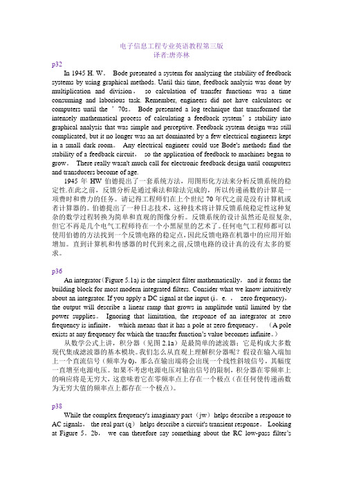
电子信息工程专业英语教程第三版译者:唐亦林p32In 1945 H. W。
Bode presented a system for analyzing the stability of feedback systems by using graphical methods. Until this time, feedback analysis was done by multiplication and division,so calculation of transfer functions was a time consuming and laborious task. Remember, engineers did not have calculators or computers until the ’70s。
Bode presented a log technique that transformed the intensely mathematical process of calculating a feedback system’s stability into graphical analysis that was simple and perceptive. Feedback system design was still complicated, but it no longer was an art dominated by a few electrical engineers kept in a small dark room。
Any electrical engineer could use Bode's methods find the stability of a feedback circuit,so the application of feedback to machines began to grow。
电子信息工程外文翻译--杜比实验室谈杜比

毕业设计(论文)外文资料翻译系别:信息专业:电子信息工程班级: 081姓名:学号:附件:1.外文资料翻译译文;2外文原文指导教师评语:签名:年月日Dolby laboratory on DolbyAuthor: TigerMultichannel perceptual codingDolby AC-3is a kind of efficiency, quality and functional aspects with unprecedented effect perceptual digital audio coding technology. From the beginning of 1992, it has been for the cinema provide multichannel digital audio system and achieved in 1994into the two channel I BS application. It in the cassette and disc type family television system for transmitting multichannel digital sound function has been to the consumer electronics industry with very excited. In the United States, high definition television ( HDTV ) broadcasting the selected Dolby digital surround sound transmission, estimated that in 1996will be put into a test screening.Many have been announced and the potential applications of the technology of test shows, Dolby AC-3decoder has a beautifully versatility. AC-3 is not a single machine system, but a kind of use can make such as bit rate and number of channels such parameters to adapt to different special application flexible procedures for the treatment of familial. Various types of all decoder in order to work on the same principle as the foundation, and designed to take full account of the future need for compatibility and adaptability. Important is, Dolby AC-3will be high quality sound and excellent digital efficiency is very perfect combination. Because of the Dolby Laboratory for more than 20 years focus on human auditory research, in the development of signal processing field has accumulated rich experience, so, although AC-3than in the CD disk to the last channel lower bit rate to create a multi-channel surround sound, however, it makes the sound quality fully meet the listener expectations.Audio : past present and futureIn 30, the famous Baer Laboratories began using the three channel stereo sound. In 50, when the stereo into public movie, it uses the channel in four above, sometimes reaching over seven channels. A few years later, the stereo into families, since all of the phonograph records only with dual channel matching, so the family leave acoustic device only by dual channel playback, the technical limitations, can not the listener will generally two-channel stereo as the home audio selection criteria.But the film makers have channel 1( left, right, center ) and surround channel2as a compelling vivid sound minimum requirements. This can be from 70 time end, eighty time period the film industry widely adopted Dolby stereo to record film confirmed, Dolby stereo is the principle, let four channel matrix coding input two optical sound track, then an appropriate audio processor will restore it into four channels matrix coding reproduction.When Dolby stereo film is converted into audio signals, four channel coding retained the dubbing integrity, from 80 time begin first, Dolby surround has made multiple channel decoding into family time, today, tens of thousands of home audio systems are equipped with Dolby surround sound system, in fact, multi-channel surround sound system sales has been farbeyond the two-channel stereo system sales, at present, Dolby surround sound has been widely used in film, TV and music on CD recording studio, and its accompanying family Dolby surround systems on the market rapid development.With multi-channel audio in consumer electronics in the field of rapid growth, a more advanced technology was born, the technology is born there is nothing comparable to this, it has simulated realistic sound effects, and can satisfy various listening conditions and high demand cannot imagine adaptability, this is Dolby AC-3decoding technology Dolby AC-3 decoder, the successful development and application, is the world's electro-acoustic industry a major achievement.Dolby AC-3In 1987, high-definition television channel in the United States has officially become the standard process, its audio track is used for the first time in the four channel matrix encoding conversion for transmission of digital code stereo. However, by 1990, in order to avoid audio matrix are affected, four mono or stereo combined configuration as the optimal configuration. Due to time technical limitations, such an arrangement would have to increase by at least a bit rate.It is in this context, Dolby AC-3was born. It has the advantage of only two independent stereo more code rates can realize multi-channel audio code. Dolby advanced to the transmission of the code technology, such as Dolby AC-2 decoder for Dolby AC-3's successful development paved the way, but the complexity of multichannel code also need further research, including a new type of bit allocation technique.The Dolby laboratory is established by Rui Milton Dolby. Dr. Dolby was born in 1933 in the United States Portland Oregon City, grew up in the San Francisco Bay area. At the age of 16 he was still in high school, in Ampex company works. The company is the United States 's first production of magnetic tape recording equipment manufacturers. Later, he is responsible for the development of the company developed the world's first practical VCR portion of an electronic circuit.In 1957 Dolby graduated from Stanford University, University of Cambridge, Marshall won the British provided scholarships, study of L-band X light. In 1961 he received a doctor's degree in physics. In 1963, he accepted the UN appointed to India as a two-year consultant.As an amateur recording enthusiasts, Dr. Dolby over the years to recognize on the tape recording audio or video signal when background noise on the recording quality damage. While in India he began thinking seriously about a noise reduction without compromising the recording quality approach. His exploration of these became the Dolby A B noise reduction and noise reduction, noise reduction system based on C.In 1965, returning to England, in London he established his own laboratory in order to carry out in India he thought scheme. Set up in 1968 to" the Dolby lab" named company. Although the company was founded10 years ago, the work of the centre in the UK, but it has been an American company. After 1976, the company's main work moved to San francisco.In 1965, the first Dolby A type noise reducer ( A representing audio Audio ) production out of. The design of the system for a variety of audio noise reduction application, especially can solve the studio recording tape when the tape recorder generated noise. Until 1966, there have beenseveral noise reducing technology available, but they are much to damage the recording quality. So Dr Dolby faced difficulty is how to make the personage inside course of study and potential customers to believe his technique. At that time, multitrack recorder, from the 4 rail, track 8, track 16to 24 track, start the application, when multitrack recording tape audio mixing, the mixing of the two track tape noise level than double direct recording of the master tape is much higher.In 1966January, Decca Records UK Department believes that Dolby A type noise reducer can indeed as Dr. Dolby described that play a role, and then ordered9Dolby A301A type noise reducer, applied for the first time in 1966May in Vienna to record Ashe Ken that Qi played some of Mozart's piano concerto. In 1966November, Decca published the first application of Dolby A type noise reducer record by Georg Solti / Muller second symphony. Subsequently, the recording industry began to recognize and use a large amount of Dolby A type noise reduction system. Initially used only recorded classical music, when multitrack recording technology promotion, will be more widely applied. Soon, the whole world of professional and non-professional begin to" Dolby" with high quality recording together.With the hope that Dolby will be present and noise reduction technology for civilian recorder voice rising, in an American commercial tape recorder manufacturer KLH company 's urging,1967April Dolby lab started to develop more practical civil noise reduction technology, initially known as the" simplified Dolby system", which later became known as Dolby B type noise reduction technology. In the Dolby B noise reduction technology development is nearing completion, Dr. Dolby made the decision, Dolby laboratory will not civilian production of audio products, consumer electronics products, but to the manufacturers authorized Dolby technology has been very mature, then by manufacturers for production. By the end of 1974, the Dolby laboratory authorized manufacturers already amounted to 47, including all consumer audio equipment manufacturers.Thereafter, Dolby laboratory has developed a series of Technology: C type noise reduction, SR ( spectral recording ), S type noise reduction, HXPro, stereo surround Dolby, Dolby, Dolby Pro Logic, AC1, AC2, Dolby digital ( AC3), Dolby E. These techniques are widely used in civil and professional audio equipment, sound recording film, cinema playback apparatus, digital broadcast etc..In addition to the headquarters in San Francisco, Dolby laboratory at present in the world have established branches or liaison offices: Losangeles, Wootton Barcelona ( UK), London, Brisbane, New York, Tokyo, Shanghai, Beijing, Hongkong.AC-3 multi-channel frameDolby surround ( Dolby Surround ) is the original Dolby multichannel film analog format consumer version. In the production of Dolby surround sound, a 4Channel -- left, right, and surround sound channel audio information through matrix coding in two tracks on a record. The two tracks from stereo format program source such as a video and television broadcast program and carrying into the family, and decoded the original 4channels of information can be reduced and surround sound. Hundreds of thousands of home videos and TV shows by Dolby surround coding." Dolby surround ( Dolby Surround ) as the most primary surround sound standard, provides a 4channel surround sound support.Dolby surround and DTS surround is similar in that they are lossy digital compression technology. This is referred to as" emotional" data compression technique is based on the human psychoacoustics that possess sound characteristics -- for high level sensitive voices, while shielding the other is not sensitive to the sound development of.Because Dolby stereo is a coding technology of digital stereo, and decoding technique uses a direction identifying circuit or a directional logic circuit, so that the use of Dolby company this circuit technology of sound is called Dolby Pro Logic sound; with Dolby 's proprietary specific decoding technology is called a Dolby Pro logic decoder decoder.Of course, only with the use of Dolby to the logic function of the AV amplifier, played by Dolby sound recording software, can hear the true high fidelity digital stereo sound effect. Dolby digital systems will generally be5.1 channel sound compression to 384bps, and some CD with 448bps, the maximum to the 640bps; DTS usually use much larger bit rate --1536bps. If other conditions are the same, is a bit more quality is better, this assertion is wrong? Unfortunately, the answer to this question is not so easy, because the Dolby Digital ( abbreviated as DD ) and DTS data compression circuit is different. For example, a coding efficiency very low signal, even if the bit rate is very high, also just wasted bits and disc space, but does not improve sound quality. Once a system is said to be" transparent", increase the bit rate without causing it to improve the sound quality. In addition because the DTS bit rate higher than Dolby, need takes up more space, if the DVD disk capacity constraints, may produce adverse effects on image quality, or to increase the additional cd.Dolby Pro-Logic surround sound ( Dolby Pro Logic ) is Dolby developed a surround sound system. It is the four track stereo recording by a specific encoding means for the synthesis of two channel, the original left channel ( L ), the right channel ( R ), the center channel ( C ), surround channel ( S ) of the 4signal, encoded into LT, RT composite double channel signal, replay through the decoder will encoded two-channel composite signals LT and RT reduction for encoding the left, right, in around four, each stem and independent signal, amplified respectively input left, right, center and surround sound speakers.In order to playback symmetry reasons, surround speakers using the left and right surround speakers, respectively, from the output of the amplifier, so the business to Dolby Pro-Logic surround sound output called channel five. But due to a left, right surround sound speakers connected in a channel, the output is the same as the surround channel information, the essence is still four channel. The business also has six channels and seven channels Dolby Pro Logic AV amplifier. The six track is the central channel two amplifying circuit is respectively connected with the output, in left center speaker and right center speaker. But left, right center speaker connected to a center channel, it is essentially a four channel. Seven channel surround sound channels is divided into four channel output, i.e. left rear surround, right rear surround sound, and adopts four surround sound, which became a seven channel output. But the output of the seven track four surround speakers are connected in a surround channel, also can calculate the output of four sound channels. So with Dolby Pro logic decoder AV amplifier whether five channel output, six channels of output or the seven output channels, is essentially a four channel. Dolby Pro-Logic surround sound in the left, right, three channel frequency range can reach 20-20000Hz, can meet the full range of requirements, but surround channel frequency range is narrow, only 100-7000Hz.Dolby E is designed for digital TV broadcast and post-production and the design of aprofessional audio coding system. Using the Dolby E, a AES / EBU channel can send up to 8channels of high quality digital audio stream, and also can be loaded Dolby digital control data signals (often called the metadata, including the Dolby digital mono mode, dynamic range, type, output level automatic adjustment of parameters, to ensure that users can correct Dolby digital program ). Dolby E with its advanced coding algorithm and higher data transmission rate, can ensure the digital TV audio signals through as many as 10cycle coding - decoding or other editing process, and does not cause quality deterioration. Dolby E audio can be associated with various formats of video signal is a good match, won't because video interference blind audio, sound burr or other distortion. Dolby E audio and video frames in the sequence are completely corresponding, can achieve precise audio and video integrated editing. More importantly, by use of this new type of coding technology, the existing radio and television system without large-scale transformation can spread multi-channel digital TV audio signals, thereby greatly reducing the system cost.Dolby E application is in digital television stations intermediate transfer, from a local television program transmitted by satellite to another local TV station. Dolby E in conveying to the transmitting terminal will be converted to PCM audio, and then encoded into Dolby digital signal, transmitted to thousands of households. Therefore, consumers in the home can be directly received by Dolby E signal, but only receives a digital signal on channel 5.1Dolby. In order to avoid the confusion, usually Dolby E called transfer coding system, and Dolby will be called to launch digital coding system.Dolby E standard data transfer rate is 1.92Mbits / sec (20bit / 48kHz for audio signal ), typical operating mode is "5.1+2", using six channel transmits a 5.1channel surround sound signal, the other two channel transmission of two-channel matrix coding signal ( such as Dolby Pro-Logic surround sound ) or dual mono stereo signal. Can also work in other modes, such as with two mono signal"5.1+1+1" pattern, three way stereo signal "3x 2" mode and a six single channel signal"6x 1" mode. Dolby's current version supports 29.97fps frame rate ( NTSC standard, PAL25FPS ),20bit length and 48kHz sampling frequency of the audio signal, a future version will support25FPS,16bit or24bit audio signal.AC-3 transmission formAC-3 based transmission system into a more extensive application field is feasible in technology. At the end of the century before, several AC-3 based application technology into commercial production.High definition television ( HDTV ) is declared using a AC-3 code first application technology. Grand Alliance has selected the United States developed this technique. For its high definition television system with digital surround sound and in 1996Atlanta Olympic Games for the first time as media.Because the AC-3effects and can be associated with high definition television matches the standard features of digital cable TV system, therefore, is a natural candidate for AC - 3. The first test transmission was 1994year. Due to the current available programs can use a single sound, stereo can also use with matrix ( matrix - sur-round ) stereo, therefore, a AC-3dual channel decoder for has been developed. And when the multi-channel digital program for transmission, high function converter ( converter ) will create a synthetic stereo downwardmixing effect.Always as home theater the highest quality image source DVD ( (LD ) as Dolby surround digital multi-channel audio examples show. Using AC-3bit stream ( bit stream ) alternative FM channel in a channel, so that the stereo pulse code modulation ( PCM ) digital audio soundtrack with FM mono cooperate with each other, so that it can be compatible with existing any player. With cable, DBS and DAB is realized by AC-3spectrum effect, quality and multi channel features a unique mix of choice. The first use of AC-3DBS system has been introduced in 1994, it can be for commercial organizations to provide a single transmitter transmission up to 120 stereo music channel transmission system.Other areas of application include medical telemetry devices suitable for very low bit-rate code under development. Potential users and system developers and the Dolby laboratory, in order to obtain the AC-3 technical support.AC-3 integrated circuitDolby surround digital main technical progress is Rolland ( Irap ) Company IR38000, which is a can perform AC-3decoder to decode single chip digital sound field processor ( DSP ). It was first used in second generation Dolby stereo digital cinema in the decoding unit.A Rolland company development, lower cost, especially suitable for consumer electronics equipment and also can provide the program logic decoding ( Pro Logic decoding ) AC--3 decoder integrated circuit in the middle of 1994launch. This is a dual channel integrated circuit chip can be used, such as cable television 's top decoder. Other semiconductor manufacturers have been or are ready to supply the AC-3 decoder integrated circuit.Dolby and digitalAC-3 is Dolby's laboratory developed the third generation of perceptual coding system. Each code system will be a special psychological acoustics ( psycho acoustics ) knowledge and advanced digital signal processing technology combine very well.AC-1 initially by the Australian Broadcasting Corporation in 1985 for its DBS system. Perhaps partly because AC-1 decoder cost reasons, it appears to be widely applied to other DBS services, satellite communication network and digital" wired broadcasting system". According to their different applications, each channel code rate for 220-325bit / sec. As an adaptation of delta modulation ( ADM ) in the form of a digital stream, ( datastream) contains information not by audio signal absolute value provided, but by different sampling ( Sample ) value changes identified. By Dolby transform to noise reduction techniques, such as: continuous transformation step and pre-emphasis can greatly improve the adaptation of delta modulation ( ADM ) basic performance.Dolby AC-2advanced adaptive transmission code used in professional audio transmission and storage, which each channel digital rate of 128 or192day / sec. Narrow band multiplicity of frequency control signal program fully adopted the noise masking superiority, resulting in an efficient reduction rate and high signal transparent effect. In other applications, such as: a long distance transmission, real time (real-time ) recording, mixing and adding storage ( ADR ) are very widely used for connecting remote recording studio or film shooting field. AC =3 is alsoused to connect the BBC Transmitter Room and the Dolby DSTLR system core equipment. AC-3 is in the AC-1and AC-2is developed on the basis of multi channel coding technology, to retain the original AC - 2such as window function, exponential transform coding, adaptive bit allocation and many other features, but also a new stereophonic sound channel coding technology strategy for the coupling and rematrix algorithm. In general, the stereo left channel and a right channel signal in the sense of hearing is very similar, there are many repetitive redundancy information, will be the two channel signals combine to be coded, can remove redundant signal and will not affect the original sound quality. Here AC-3array low bit rate and an effective means of.AC-3PC voice data input, output the compressed digital bit stream. Coding is the first step, using the TDAC ( Time Domain Aliasing Cancellation ) filter the time-domain PC sampling data is transformed into a frequency domain blocks into a series of transform coefficients, each transform coefficient in binary exponential notation, namely an exponent and a mantissa. Exponent part encoded constitutes the entire signal substantially the spectrum, also known as the spectral envelope. Using the spectrum including and shaded by line correlation decision each mantissa bit allocation. Because the bit allocation is adopted in the anterior / posterior to the hybrid adaptive bit allocation and public bit pool technology, which can make the limited rate in the channel between the different frequency components, between the rational allocation of the mantissa; in quantization process, the mantissa is shaking, shaking the pseudo random number generator can be on a different platform to get the same results. By the end of six blocks of the spectral envelope, coarse quantization of the mantissa and the corresponding parameters consisting of AC-3 data frame format, continuous frame merged into a digital stream output.By the time domain is transformed to the frequency domain block length selection is the exponential transform coding based on. As defined in AC-3two length switching, a512sample value point of the long block, a256sample value point of short block. In the analysis of signal spectrum, to deal with the channel signal blocks cut made longer, so that you can get a better frequency resolution, but also can get higher coding efficiency. But long data block may contain a number of different possible recognition of noise, such as pre-echo. That is to say the ear due to time and frequency exists on the shadowing effect in the exponential transform coding is a contradiction, not at the same time, must plan as a whole processing. For the steady state signal, whose frequency varies with time transform slow, in order to improve the coding efficiency, requirement filter has good frequency resolution, which requires a long block; as for the rapidly changing signal, requires good time resolution, which requires a short block. In the encoder, the input signal after3Hz high-pass filter removes the DC component, and then through a8kHz high-pass filter out high-frequency components, with its energy are compared with a preset threshold, in order to detect the signal transient situation.AC-3based on the modified discrete cosine transform ( MDCT ) adaptive transform coding ( ATC ) algorithm. Although defined in AC-3 standard MDCT transform, but the actual using a N / 4IFFT ( FFT ), plus two simple Pre-IFFT and Post-IFFT as adjustment, in order to achieve a N IMDCT transform. ATC algorithm is an important consideration is based on auditory masking effect critical band theory, namely in the critical band within a voice to another voice signal shielding effect the most obvious. Therefore, dividing the band filter group to have fast enough to ensure that critical band frequency response, and noise attenuation is large enough,the time and frequency of noise within the defined in the masking threshold.The AC-3 encoder bit allocation technique, has been applied widely on the forward and backward adaptive bit allocation rule. Forward adaptive bit allocation method is the encoder calculation, and the bit allocation information explicitly incorporated into the stream of data bits, and is characterized in that the front end of the encoding process uses auditory model, thus modifying the model the receiving side decoding process has no effect; the disadvantage of reducing coding efficiency, because of the need to transfer the bit allocation information while occupying a part effective bits. To the adaptive method did not get encoder clear bit allocation information, but from a digital stream in which the bit allocation information, has the advantages of no occupation of the effective bits, thus has higher transmission efficiency. Its drawback is from received data to calculate the bit allocation, if the calculation is too complex to the rising cost of decoder. In addition, the decoder algorithm also with encoder auditory model change. AC-3using hybrid backward / forward adaptive bit allocation, in enhancing the rate and reduce the cost of strikes a balance between.AC-3 decoder decoding principle basically is encoded by the reverse process, firstly, the decoder must with the encoded data stream synchronization, and then from a data error correction of digital flow separation control data, system configuration, the encoded spectral envelope and the quantized mantissas and other content, according to the sound spectrum envelope to generate the bit allocation information, the mantissa part of inverse quantization, restoring the transform coefficient exponent and mantissa, after synthesis filter banks, the data from the frequency domain to time domain, the final output of the PCM sample signal reconstruction.Through the understanding of AC-3, you can see the AC-3technology makes full use of the human ear sensory model, according to the different properties of signal, to take the corresponding effective algorithm, achieved at a high quality under the premise of achieving a higher rate for the intended purpose, is a very efficient and economical digital audio compression system. AC-3 is the American digital television system of mandatory standard, is the European digital television system recommended standard, at the same time, AC-3or DVD system of compulsory standards. At present our country is the development and promotion of digital TV system, all have reasons to believe that AC-3 technology will have a good prospect of application.Dolby Chun chamber ( About DolbyLaboratoies ) from the analog noise reduction ( analog noisereduction ) to the digital code ( digitalcode ), Dolby has concentrated on rooted in laboratory to ear sound perception based audio processing development. In the process of development, Dolby has always been the emphasis is on the critical listening and tested. Either analog or digital program program, their results are the same, with low cost, greatly improves the efficiency of communication media. In some cases, it also for the improvement of new products, such as: Dolby surround sound ( DolbySurround ) and home theater ( home theater T ) make contribution.The Dolby laboratory consists of the following components: investment and Technology Development Engineering Department, occupation audio product design and manufacturing sector, experts the organization and distribution of all over the world in the field of support group. Dolby products from companies located in modern American and British manufacturing plant. Lyrics by the world's major consumer electronics manufacturers group; for each license。
- 1、下载文档前请自行甄别文档内容的完整性,平台不提供额外的编辑、内容补充、找答案等附加服务。
- 2、"仅部分预览"的文档,不可在线预览部分如存在完整性等问题,可反馈申请退款(可完整预览的文档不适用该条件!)。
- 3、如文档侵犯您的权益,请联系客服反馈,我们会尽快为您处理(人工客服工作时间:9:00-18:30)。
英语原文:Life of LED-Based White Light SourcesThe interest for using light-emitting diodes (LEDs) for display and illumination applications has been growing steadily over the past few years. The potential for long life and reduced energy use are two key attributes of this rapidly evolving technology that have generated so much interest for its use in the above mentioned applications. Traditionally, the lamp life of light sources commonly used in illumination applications is determined by subjecting them to a predetermined on/off cycle until half the number of light sources cease to produce light. Unlike these sources, LEDs rarely fail catastrophically; instead, their light output slowly degrades over time. Even if an LED is technically operating and producing light, at some point the amount of light produced by the LED will be insufficient for the intended application. Therefore, the life of an LED should be based on the amount of time that the device can produce sufficient light for the intended application,rather than complete failure. Based on this argument, a recent publication from an industry group defines the life of an LED device or system for use in general lighting applications as the operating time, in hours, for the light output to reach 70% of its initial value.The most widely used white LEDs incorporate a layer of phosphor over a GaN-based, short-wavelength light emitter. Usually, the phosphor is embedded inside an epoxy resin that surrounds the LED die. Some portion of the short-wavelength radiation emitted by the LED is down-converted by the phosphor, and the combined radiation creates white light.Early white LEDs were packaged similar to the indicator-style colored LEDs, specifically 5 mm and SMD (surface mount devices). Although these products demonstrated the concept of a white light source, they did not produce sufficient light for display and illumination applications. Furthermore, these indicator-style white LEDs had a relatively short life, 5000–10 000h to reach 70% light level under normal operating conditions. To address the higher luminous flux requirements, manufacturers have started to commercialize high-power illuminator LEDs that are presently producing over one hundred times the flux compared to indicator-style white LEDs. The higher light output isachieved by using larger dies, higher drive currents,and improved heat extraction methods. In addition,some manufacturers are using better encapsulants to improve the life of white LEDs.There are several studies that have investigated the aging mechanisms of GaN-based LEDs. During the 1990s,Barton et al. investigated the degradation of GaN-based blue LEDs and showed that light output reduction over time occurred primarily due to the yellowing of the epoxy surrounding the die. In 2001, Narendran et al. observed that indicator-style white LED packages degraded very rapidly, with the LEDs reaching the 50% light output level within 6000 h. In that same study, it was shown that the chromaticity values of the white LEDs shifted toward yellow over time, and it was speculated that the yellowing of the epoxy was the main cause for light output degradation. Therefore, based on past studies,the primary reason for the degradation of indicator-style white LED packages is the yellowing of the epoxy that is caused by excessive heat at the p-n-junction of the LED. Some of the newer illuminator-style white LEDs use encapsulant materials that have lower photodegradation characteristics,and therefore have a lower degradation rate. However, there are factors such as the degradation of the die attaché epoxy, discoloration of the metal reflectors and the lead wires, and degradation of the semiconducting element that are influenced by heat, and these all contribute to the overall degradation of the white LED. Although the newer high-power white LEDs would have a lower degradation rate compared to the early indicator-style devices, it is the heat at the p-n-junction that most influences the degradation. The heat at the p-n-junction is caused by the ambient temperature and the ohmic heating at the bandgap.As stated earlier, long life is one key feature of LED technology that has attracted so many end-use communities. To benefit from the long-life feature, it is the final system that has to operate for a long time, not just the individual LED. As noted in past studies, heat at the p-n-junction is one of the key factors that determine the life of the white LED. Therefore, if systems are not properly designed with good thermal managemen techniques, even if they use long-life white LEDs the life of the final system would be short. Developing the relationship between junction temperature and life would be very usefulfor producing long-life systems.Although there are different methods available for estimating the junction temperature of LEDs, they are not very convenient,especially once the LEDs are integrated into a system . Furthermore, these methods are not direct; consequently, they are prone to erroneous results. Alternatively, it is much more convenient and direct to measure the heat at a location external to the LED package that is sufficiently close to the junction and where a temperature sensor can be directly attached. The temperature of this point should have a good relationship to the junction temperature. The point where a temperature sensor can be attached for this measurement could be the lead wire (cathode side) for the indicator-style LEDs and the board for high-power LEDs. Most manufacturers can recommend such a point,and we refer to this as the T-point in this manuscript.Since white LEDs in the marketplace are packaged differently, their ability to transfer heat from the die to the surrounding environment is different from product to product. Therefore, it is reasonable to assume that different products have different degradation rates as a function of heat. A graph that shows the life of the LED as a function of T-point temperature is extremely useful for system manufacturers to build reliable, long-lasting systems. By knowing how much impact heat has on the degradation rate or life of the LED, the system manufacturer can select components and drive parameters, including the amount of heat sink and drive current, for a product being designed for a given application.Therefore, the objective of the study presented in this manuscript was to investigate the relationship between the T-point temperature and life of a white LED. A second objective was to understand the degradation rate of different high-power white LED products presently available in the marketplace.To understand the relationship between the T-point temperature and life, one type of high-power white LED that is commonly available in the marketplace was selected. Several of these LEDs were subjected to a life test under different ambient temperatures. The details of the experimental setup are described in the following paragraphs.Because the different LED arrays have to operate at a particular ambient temperature, the arrays were placed inside specially designed, individual life-test chambers. The test chambers had two different functions: 1) to keep the ambient temperature constant for the LED arrays and 2) to act as light-integrating boxes for measuring light output. Each individual LED array was mounted at the center of the inside top surface of a life-test chamber. A photodiode attached to the center of the left panel continuously measured the light output.A small white baffle placed over the photodiode shielded it from the direct light, allowing only the reflected light to reach the photodiode. A resistance temperature detector placed on top of the baffle measured the chamber’s ambient temperature and controlled the heater that provided the necessary heat to the chamber through a temperature controller. The temperature in-side the box remained within ±1℃.The heater was attached to a raised aluminum plate with a matte-white cover that sat on the chamber floor. The temperature was estimated using a J-type thin wire thermocouple soldered to the T-point of white LED. For each chamber, an external LED driver controlled the current flow through the LEDs. All life-test were placed inside a temperature-controlled room. The life-test chambers were staggered vertically and horizontally to ensure that heat rising from the bottom chambers did not affect the chambers above them.The results of this study underscore the importance of packaging white LEDs using proper thermal management to maintain light output, and thereby extend system life. Heat at the p-n-junction is one of the main factors that affect the life of white LEDs. Therefore, knowing the relationship between life and heat would be very useful for manufacturers who are interested in developing reliable, long-lasting systems.Results from the first experiment—conducted under various ambient temperatures to understand the relationship between T-point temperature and life—indicate that life decreases with increasing temperature in an exponential manner. Results from the second experiment—conducted to understand how different commercial white LEDs perform under identical operating conditions—show a large variation in life among the different packages, indicating that the packages used different heat extraction techniques and materials.As part of ongoing research, we hope to further investigate how the different commercial LEDs are affected by heat and finally develop a family of curves that illustrate the relationship between life and T-point temperature for the different products.中文翻译:基于LED的白色光源的寿命在过去几年中利用发光二极管(led)显示和作为照明应用的技术一直在稳步增长。