matlab制作信号发生器
基于matlab 信号发生器设计
三.信号发生器设计
1.信号发生器程序框图设计
首先先在程序面板上找出基本信号发生器,在分别标添加输入为、幅值、预设频率、占空比、输出频率;然后再添加输出为波形图
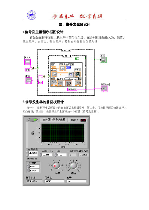
2.信号发生器的前面板设计
第一步,先把程序版所设计的在前面版上排版整理;第二步,用控件里面的修饰选择上凹凸选项;第三步,在波形显示上面添加一个标签(信号发生器)。
运行结果:
三角波
正选波
方波
锯齿波
3.结束语
设计的信号发生器可以实现在波形显示波形信号, 信号的相位和幅值还有频率均可自己调试。
适合于科研分析。
基于Matlab_DSP Builder的正弦信号发生器设计

基于Matlab/DSP Builder的正弦信号发生器设计引言近年来随着通信技术的不断发展,信号的正确传输显得日益重要,也就是说要有一个可靠的能产生稳定确信号的发生器,基于Matlab/DSP Builder的正弦信号发生器是利用Matlab/DSP Builder的模块进行的模快化设计,软件的设计采用模块化结构,使程序设计的逻辑关系更加简洁明了、易懂、易学。
使硬件在软件的控制下协调运作。
DSP Builder可以帮助设计者完成基于FPGA的DSP系统设计设计,除了图形化的系统建模外,还可以完成及大部分的设计过程和仿真,直至将设计文件下载到DSP开发板上。
此次实验的目的就是将两者的优势有机的结合在一起,利用DSP的优势开发正弦信号发生器。
在设计中主要采用DSP Builder库中的模块进行系统的模型设计,然后再进行Simulink仿真。
1.设计思想1.1 DSP Builder特点DSP Builder系统级(或算法级)设计工具,它架构在多个软件工具之上,并把系统级(算法仿真建模)和RTL(硬件实现)两个领域的设计工具连接起来,最大程度的发挥了两种工具的优势。
DSP Builder依赖于MathWorks公司的数学分析工具Matlab/Simulink,可以在Simulink中进行图形化设计和仿真,同时又通过Signal Compilder把Matlab/Simulink的设计文件(.mdl)转换成相应的硬件描述语言VHDL设计文件(.vhd),以及用于控制和编译的tcl脚本。
而对后者的处理可以用Quartus II来实现。
1.2 QuartusII特点QuartusII提供了完整的多平台设计环境,能满足各种特定设计的需要,是单芯片可编程系统(SOPC)设计的综合性环境和SOPC开发的基本设计工具,并且为Altera DSP开发包进行系统模型设计提供了集成综合环境。
QuartusII完全支持VHDL的设计流程,其内部嵌有VHDL逻辑综合器。
基于MATLAB的函数信号发生器1
基于MATLAB的函数信号发生器1信息系统仿真设计实训报告学院信息电子技术专业****班级******8学号********8姓名***指导教师***2014年7月25日基于MATLAB的函数信号发生器1、目的函数信号发生器是基于软硬件实现的一种波形发生仪器。
在工工程实践中需要检测和分析的各种复杂信号均可分解成各简单信号之和,而这些简单信号可由函数信号发生器模拟产生,因此它在工程分析和实验教学有着广泛的应用。
MATLAB 是一个数据分析和处理功能十分强大的工程实用软件,他的数据采集工具箱为实现数据的输入和输出提供了十分方便的函数和命令,在信号处理方面方便实用。
本文介绍了使MATLAB建立一个简单函数信号发生器的基本流程,并详细叙述了简单波形(正弦波、方波、三角波、锯齿波、白噪声、脉冲)信号的具体实现方法。
通过此次的设计对MATLAB有个更深刻的了解,熟练的使用MATLAB的GUI设计简单的界面程序。
2、工作原理与计算该虚拟信号发生器的设计由GUI界面及其对应的程序组成。
设计函数发生器有正弦信号、方波信号、三角波、锯齿波、白噪声、脉冲信号。
其中,前五种波形都可以利用MATLAB提供的函数实现,并根据输入的幅值、相位、频率等信息进行调整。
根据脉冲信号在某一时刻出现的一冲激特点,可由编写程序来实现。
界面主要由MATLAB创建,之后编写界面所用的函数,从而实现函数信号发生器。
(1)正弦信号的实现正弦波信号的数学表达式如(1)。
ωφ()其中:A为幅值;ω为频率; 为相位。
在MATLAB中,幅值、频率、相位、在用户界面输入。
y的表达式都得到以后,用plot二维作图函数获得波形显示。
(2)方波信号的实现与正弦波一样,从用户界面获得幅值、频率、相位、采样频率等信息,用square 函数获得对应y坐标值,用plot绘图,格式如(2)。
()其中duty为占空比。
(3)三角波和锯齿波的实现这两种波形的表达式皆要借助于sawtooth命令。
基于MATLAB的可控DDS正交信号发生器的设计与实现
D S Drc ii y tei r 直 接数 字 合 成 器 , D ( i t gt S nh s e ) e D a l z
是 一种 采用 数 字技 术 的新 型频 率 合 成 技 术 , 过 控 制 通 频 率 、 位 增量 的步 长 , 生 各 种 不 同频 率 的信 号 , 相 产 具
2 t… . A) 来表 示 , 只要 这 些采 样 点 的 时 间 间隔 ≤l /
在广 电前端调制等设备和其他数字信号处理领域
中 , 多应 用 都需 要 正 交信 号 , 果 由 A I 片或 由 很 如 SC芯 分离 器件 来 实现 , 设计 成本 高 , 而且 不容 易达 到设 计需 求 。本 文 利 用 MA L B强 大 的仿 真 功 能 和 F G 灵 TA PA
sz r ie ,wh c s b s d o h ih i a e n t e MAT LAB.I h s p p r n t i a e ,we g v re y a ay i n t o c p f t a e a b i f n l ss o he c n e to he DDS l a d a ma h mo li h n t de n te MATL AB.I he me n ie,us d t e ha d r s rp in l n u g o r aie a d n t a wh l e h r wa e de c i to a g a e t e z n l v rf h s mo e n a f g lc i e y t i d lo u a hp. i d man. o i e d sg a u tt e fo te d e u p n sa t e i i in lp o e s e in c n s i h r n — n q i me t nd o h rd gt sg a r c s l a
基于MATLAB的信号发生器设计说明
方波(square)
方波参数如表3所示。设采样率:samp
数组表示: t=0:(1/samp):1; y= offset + amplitude* sign(duty/100/ frequency -mod(t,
硬件设定(板卡选择和通道选择)
板卡选择
源代码段: out = daqhwinfo; device=out.InstalledAdaptors set(handles.device,'string',device);
说明:daqhwinfo.InstalledAdaptors包含安装的硬件 板卡的信息,将其加入作为下拉列表框的选项。
说明:t在1秒内有samp个均匀采样点,y做为samp×1的一维数组 输出到板卡的一个通道。频率变化的方式不同,输出表达式也不
同。
注意:method有两个选项:linear和log;
符号“./”用于数组间运算。
自定义波(self-define)
自定义波参数如表8所示。设采样率:samp
MATLAB的GUI设计中,有两种设计方式:利用GUI编辑器和编写M文
件。
GUI是用户的操作界面,是选择波形、设定和修改波形参数、
设定采样率、选择输出通道和运行、停止程序的人机交互接口。
本程序的界面中,可选波形包括正余弦(sin),Sa波(sinc),
方波(square),三角波(triangle),锯齿波(tooth),噪声
数组表示: t=0:(1/samp):1; y=offset+amplitude*sin(2*pi*frequency*t+phase*pi/180+eps)
基于MATLAB的信号发生器设计

因为 PCI-6024E 只有 2 路 DAC,所以输出通道的选择只有这 2 路,或者只输出其 中的一路。运行、停止则是开始和停止计算波形、输出波形的过程。编写 M 文件 来处理 GUI 界面的事件的响应。
本设计的独特之处在于输出通道的可选择性,可选择 NI-DAQ(PCI-6024E), 声卡,或者并行等。考虑到信号幅度范围对于不同硬件也是不同的(PCI-6024E 是-10~10v),超出范围的部分是无效的,程序同样会报错并停止运行。
幅度 amplitude
文件名 filename
默认值
500
1
自定义波参数如表 8 所示。设采样率:samp
说明:本选项是信号发生器的扩展功能之一,通过菜单区操作可以读取保存
为图像和数据的文件,输出信号到输出板卡上。
①读取图像文件(*.bmp)
源程序段:
h1=imread(filename);
h2=rgb2gray(h1)
《MatLab 信号处理》
-----基于 MATLAB 的信号发生器设计
姓名: 学号: 班级: 2010.12
基于 MATLAB 的信号发生器设计
虚拟仪器能充分利用现有计算机资源,通过配以独特设计的软硬件,实现普 通仪器的全部功能以及一些在普通仪器上无法实现的功能的软件或程序。本设计 的主要内容就是基于 MATLAB 来实现一个信号发生器,除具有信号发生器一般功 能外,还应能通过文件或图形获取波形数据,以实现任意波形的生成,并以 PCI-6024 DAQ 卡作为硬件平台输出。
[m,n]=size(h2);
for i=1:n
x(i)=0;
end
for i=1:n
for j=1:m
if (h2(j,i)~=255)
基于matlab的信号发生器设计
基于matlab的信号发⽣器设计Digital Signal GeneratorYangXiao M2013705103HuaZhong University of Science and TechnologySchool of Mechanical Science and Engineering Abstract: Matlab Is a numerical analysis, matrix calculation, scientific data visualization and nonlinear dynamic state system modeling and simulation, and other functions of practical software engineering.It’s easy to use the windows environment and cast off a tradition on the interactive programming language (such as C, Fortran) Edit mode In large range. In this report,The task is to design a digital signal generator bu using matlab.It could help us to understand the signal processing by designing the digital signal generator. Which has a certain application value of reference.Keyword:digital signal generator;Matlab1.PrefaceMATLAB is called Matrix Laboratory,which is designed by the United States MathWorks company.It’s a commercial mathematical software. Matlab can be use for Matrix operations, mapping functions and data, algorithm, creating the user interface, connect to other programming languages procedures, mainly used in engineering calculations, control design, signal processing and communications, image processing, signal detection, design and financial modeling analysis and other fields. GUI (Graphical User Interface, referred to as GUI, known Graphical User Interface) is displayed using the graphical user interface of computer operations.. Matlab has a powerful GUl tool. In this report, by using matlab GUI tool we could a designed digital signal generator .2. IntroduceProgram reference implementation of MATLAB Data Acquisition Toolbox. In MATLAB design, there are two designs: the GUI editor and M-file write. This design use GUI editor . The GUI is user interface, which is to select the waveform, set and modify the waveform parameters, set the sampling rate, select the output channel and run. This program GUI interface provided: sin, square, triangle, sawtooth, while noise, to choice. Also we could change waveform parameters to change waveform’s shape. As frequency amplitude phase and sample haveprovided gave us to change.The interface is that:2.1 Interface3. Design PrinciplesThe task is to design the digital signal generator which can generate sine wave, square wave, triangle wave, sawtooth wave, and white noise. All the waveform can use MATLAB function, and could be adjusted by inputting information such as the amplitude, phase and frequency .3.1 Achieve sin signalThe mathematical function of sin wave signal is that:()sin 2y A ft πφ=+A: amplitude; f: frequency;φ: phase;t: 0:1/s:1;(s is sample); The M-program is:A=get(handles.Amplitude,'Value'); f=get(handles.Frequency,'Value'); p=get(handles.Phase,'Value');s=get(handles.Sample,'Value'); x=0:1/s:1;y=A*sin(2*pi*f*x+p); plot(handles.screen,x,y,'r'); legend('sin(x)'); wavplay(y); grid on;axis([0,0.1,-20,20]);We could run the program by setting the parameters:3.1 Image of sin signal3.2 Achieve square signalThe mathematical function of square wave signal is that:(2)y Asquare ft b π=+A: amplitude; f: frequency; b: phase;t: 0:1/s:1;(s is sample); The M-program is:A=get(handles.Amplitude,'Value'); f=get(handles.Frequency,'Value');p=get(handles.Phase,'Value');s=get(handles.Sample,'Value');x=0:1/s:10;y=A*square(2*pi*f*x+p);plot(handles.screen,x,y,'b');legend('square');wavplay(y);grid on;axis([0,0.1,-20,20]);We could run the program by setting the parameters:3.2 Image of square signal3.3 Achieve triangular signalThe mathematical function of triangular wave signal is that:(2,0.5)y Asawtooth ft b π=+A: amplitude; f: frequency; b: phase;t: 0:1/s:1;(s is sample); The M-program is:A=get(handles.Amplitude,'Value'); f=get(handles.Frequency,'Value'); p=get(handles.Phase,'Value'); s=get(handles.Sample,'Value'); x=0:1/s:10;y=A*sawtooth(2*pi*f*x+p,0.5); plot(handles.screen,x,y,'b'); legend(‘triangle ’); wavplay(y); grid on; axis([0,0.1,-20,20]);We could run the program by setting the parameters:3.3 Image of triangular signal3.4 Achieve sawtooth signalThe mathematical function of sawtooth wave signal is that:(2)y Asawtooth ft b π=+A: amplitude; f: frequency; b: phase;t: 0:1/s:1;(s is sample); The M-program is:A=get(handles.Amplitude,'Value'); f=get(handles.Frequency,'Value'); p=get(handles.Phase,'Value');s=get(handles.Sample,'Value');x=0:1/s:10;y=A*sawtooth(2*pi*f*x+p);plot(handles.screen,x,y,'b');legend(‘tooth’);wavplay(y);grid on;axis([0,0.1,-20,20]);We could run the program by setting the parameters:3.4 Image of sawtooth signal3.5 Achieve white noise signalThe mathematical function of white noise wave signal is that:y A rand length x=-2((1,())0.5)A: amplitude;f: frequency;b: phase;t: 0:1/s:1;(s is sample);The M-program is:A=get(handles.Amplitude,'Value');f=get(handles.Frequency,'Value');p=get(handles.Phase,'Value');s=get(handles.Sample,'Value');x=0:1/s:10;y=2* A*(rand(1,length(x))-0.5);plot(handles.screen,x,y,'b');legend('white noise');wavplay(y);grid on;axis([0,0.1,-20,20]);We could run the program by setting the parameters:3.5 Image of white noise signal4 Exist problemThere are many problems in the design because I didn’t use matlab and the GUI modules ever.(1) I am not familiar to the interface and operator of matlab,which lead toI program without efficiency.(2) Without systematic studying of matlab,I could not express my ideas by using succinct matlab language.(3)In the beginning, I don’t understand the handle deep, and don,t have aclear idea.5. ConclusionIn the latter study, I will be more systematic learning MATLAB this powerful engineering software, has a fight on his understanding of the macro, on the basis of multi-programming exercises to strengthen the commonly used functions and concepts of memory, and finally, contact practical, try to solve some common engineering problems.References[1] 薛⼭. MATLAB基础教程. [M] 北京:清华⼤学出版社,2011.3。
基于MATLAB的CDMA信号发生器的设计与仿真
基于MATLAB的CDMA信号发生器的设计与仿真摘要:本文首先介绍了CDMA技术原理,在应用IS-95标准的链路基础之上,完成CDMA 信号发生器的总体设计和主要模块的设计,最后通过MATLAB软件模拟仿真了CDMA信号发生器工作流程,并对CDMA信号进行了波形仿真。
关键词:CDMA;MATLAB;信号发生器;仿真随着科学技术的不断发展,人们能够随时随刻进行信息交流,不再受到时间和空间的限制。
移动通信技术综合了有线网络和无线网络的传输方式,使人们能够在自由活动中与其他移动终端进行通信,从而有效节约了资源成本,同时提高了工作效率,具有一定的社会效益和经济价值。
一、CDMA技术原理概述(一)码分多址技术在CDMA通信系统中,对用户在信息传输的过程中应用到的信号进行区别不能够完全依靠频率和时隙的不同,而是应该依靠不同的编码序列进行区分(信号的波形)。
CDMA信号从频域和石宇的角度来说是相互重叠的,接收器相关器能够在多个CDMA信号区别出使用预定编码类型的信号,对于其他使用不同编码类型的信号来说,由于与接收机的编码类型不同,所以不能够进行解调,这些信号的存在通常被称为多址干扰[1]。
(二)扩频通信技术扩频是一种传输方式,指的是传输数据信息的信号带宽大于数据信息本身的带宽,频带的扩展与所传输的信息码无关,而是由与数据信息相互独立的扩频码来实现的,在接收端用同步接收来实现解扩频和数据恢复。
通常情况下,一个信息传输速率为9.6kbps的二进制比特流在由扩频通信进行传输时带宽可以达到1.2288MH。
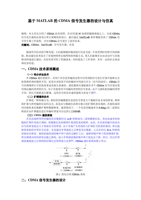
(三)CDMA通信原理在发送端将等待传输的语音数据经过A/D转换成为二进制数据信息,再由高速率的伪随机扩频序列进行调制,将数据信息的频带扩展到较宽的频带,由此,在信道传输中的语音信号的带宽就会大于原始信号的带宽。
由于本地产生的伪码与扩频信号的伪码相同,所以能够将原始的窄带信号还原,从而通过窄带滤波之后恢复语音数据,之后在经过D/A转换将原始语音恢复。
- 1、下载文档前请自行甄别文档内容的完整性,平台不提供额外的编辑、内容补充、找答案等附加服务。
- 2、"仅部分预览"的文档,不可在线预览部分如存在完整性等问题,可反馈申请退款(可完整预览的文档不适用该条件!)。
- 3、如文档侵犯您的权益,请联系客服反馈,我们会尽快为您处理(人工客服工作时间:9:00-18:30)。
Method
START
Initialize
INPUT: type amplitude frequency phase
Produce digital signal
Show the waveform
Method
• To build a GUI interface
Method
• Write M files
sin a=str2double(get(handles.editfuzhi,'String')); f=str2double(get(handles.editpinlv,'String')); x=str2double(get(handles.editxiangwei,'String')); c=str2double(get(handles.editcaiyang,'String')); t=0:8/(fs):8/f; y=a*sin(2*pi*(f*t+x/360)); plot(t,y);
Method
• Write M files
function sliderfuzhi_Callback(hObject, eventdata, handles) a=get(hObject,'value'); set(handles.editfuzhi,'string',a);
Results
• Sine waveform
Results
• white noise waveform
electric piano
• GUI interface
electric piano
• Write M files
function pushbutton1_Callback(hObject, eventdata, handles) a=2; f=131; fs=44100; x=30; t=linspace(0,1,fs); y=a*sin(2*pi*f*t+x); xianpin=findobj('tag','sinepinlv'); set(xianpin,'string',f); plot(t,y); grid; axis([0,0.05,-3,3]); wavplay(y,fs);
• Teamwork and Cooperation
Thank you!
Application
Signal generator also called signal source or oscillator,it can provide electrical signals of all kinds of frequency,waveform and phase, so it has been widely used In the field of production practice and science .
Results
• from chengshiqi
Results
• from tangmingxi
Results
• from tangmingxi
Results
• from guokai
Results
• from guokai
What’s Left to Do
• The signal generator is simple,it can not convert the RMS,mean value and amplitude.
• The only have the seven basic scales,and it unable to import audio files .
What We Learn
• Use gui to build a interface ,and write m flies to Implement specific functions.ቤተ መጻሕፍቲ ባይዱ
signal generator
by 唐铭希 郭锴 程世奇 2013.9.22
Background
MATLAB(Matrix Laboratory)is a software from the mathworks,MATLAB has a powerful tool--gui (Graphical User Interface). In this project we use the gui to create a signal generator.