以太网测试仪ETS1000使用手册
ICT 1000 Level Transmitter说明书

Quick Start Instruction ManualICT 1000 Level TransmitterNote: See Man 049 for complete installation, operation & maintenance instructions for ICT 1000 and associated RFM productsPSM WEEE Producer Registration No: WEE/HC0106WWDoc Ref: QS 049a 07/07/2015Burrell Road Industrial EstateHaywards Heath, West Sussex RH16 1TW, UK Tel: +44 (0)1444 410040 Fax: +44 (0)1444 410121 E -mail:*******************PSM INSTRUMENTATION LTDEC Declaration of ConformityThe products detailed within this manual meet the legal requirements of the applicable EC Directives.All EC Declaration of Conformities are available for download from our website .ConfigurationEach ICT 1000 is delivered with mechanical configuration (pressure cell range, mounting type and cable length) according to the customer order. Details for these can be back -referenced by contacting PSM with the unique instrument serial number engraved on each transmitter.For transmitters intended for use in analogue mode the measuring range (4 - 20mA) is normally configured according to the customer order. However this can easily be changed using a RS 485 <> Modbus converter and the PSM supplied ISS configuration software running on a Windows device. Refer to Man 053 for details.For transmitters intended for use in digital mode full application parameters will also have been factory set if requested. Again these may be easily changed or set up using the ISS software.1.11.2Prior to installation it is recommended that the following checks are made:∙ That any specific factory calibration is in accordance with the process parameters and tank height and that the ICT 1000 nominal range is suitable for the intended duty.∙ In analogue mode only, that the mA range is programmed correctly∙ In digital mode, that the application parameters such as SG, tank table, duty etc. are programmed correctly. This can be done using the PSM ISS software configuration tool.∙ Any instrument identification or tag number to ensure it is fitted in the correct location. The cable is factory fitted to the ICT ensure a pressure tight seal. and no attempt should be made to remove the cable gland.Instrument handlingBefore and during installation the following precautions should be taken∙ Do not touch the measurement cell of the ICT 1000 level transmitter∙ Do not apply mains voltage to any cable conductor∙ Ensure the ICT 1000 cable is free from damage and defectsSensor cableThe cable that is factory fitted to the transmitter is purpose designed for the application. It contains a nylon vent tube which provides an atmospheric reference for the sensor if construct-ed for a “gauge” measurement application. The end of the nylon tube has a short section of silicon tube fitted, which carries a sintered filter. This filter provides a pressure path, but pre-vents any moisture entering the vent tube and MUST remain in place. If the cable is shortened this filter must be transferred to the new cable end.Note that if the ICT 1000 is constructed as an “absolute” measuring device, then there is no requirement to vent the instrument cable to atmosphere. Precautions must still be taken however to prevent moisture ingress into the cable vent tube.The cable construction is of sufficient strength to enable the sensor to be directly suspended in deep wells and reservoirs. The outer sheathing is a special material suitable for continuous immersion in water,and many oils and chemicals. When handling the cable take particular care not to damage the outer sheathing.When a transmitter is suspended by its cable use a proprietary suspension cleat or wind three or four turns around a 100mm diameter pipe or drum. Where the cable is to be brought through the tank wall it is recommended that where possible this be done above the maximum fill line using a suitable compression fitting. (Available from PSM).Ensure the cable is not bent to a radius less than 50mm.MountingWhen mounting the unit ensure that suitable gaskets or sealants are employed to provide pressure tight seals. The sensor should not be mounted where it will be subject to excessive or continuous vibration, extreme temperature fluctuation or risk of mechanical damage.Secure the cable as required over longer runs to prevent mechanical abrasion if it moves.Do not secure the cable to any localised sources of high temperature heating such as steam coils used in heavy oil tanks.Cable is normally provided to the required length with the ends terminated as depicted above.The overall braid MUST be terminated in the entry gland of the termination enclosure to ensure it is earthed. Particular care should be taken to ensure that the 360° screen is maintained comply with the EMC standards of this unit.If, exceptionally, the cable has to be shortened, the nylon vent tube should be cut to a free length of approximately 20mm within the enclosure, it must be ensured that this tube is not blocked or otherwise restricted and the silicon tube containing the sintered filter must be re-fitted to the shortened length.The termination enclosure MUST be vented.Electrical connection ICT 1000 Analog and Digital cable identificationRed+ Power Analogue(4-20 mA) White+ Data Digital(Modbus)Black- Power Green- Data。
WFET-1000专变采集终端使用说明书范文
WFET-1000专变采集终端使用说明书范文目录123概述............................................................. ............................................................... .................-1-执行标准............................................................. ............................................................... .........-1-技术参数............................................................. ............................................................... .........-1-3.13.24外形与尺寸.............................................................. ...........................................................-1-主要技术指标.............................................................. . (2)功能描述............................................................. ............................................................... .........-3-4.14.24.34.4数据采集与统计分析.............................................................. ...........................................-3-状态监测与告警功能.........................................................................................................-4-存储功能.............................................................. ...............................................................-5-GPRS/CDMA无线数据通信功能.............................................................. .. (6)4.4.1GPRS模块主要特点............................................................. ........................................-7-4.4.2CDMA模块主要特点............................................................. .......................................-7-4.54.6停电上报功能(需要配后备电池)............................................................ ......................-8-负荷控制功能.............................................................. . (8)4.6.14.6.24.6.34.6.44.74.84.95遥控.............................................................. ..............................................................-8-电能量定值闭环控制.............................................................. ..................................-8-功率定值闭环控制.............................................................. ......................................-9-保电、剔除功 (11)软件升级功能.............................................................. .....................................................-11-对时功能.............................................................. .............................................................-11-后备电池(选配)............................................................ .. (11)调试............................................................. ............................................................... ...............-12-5.15.25.35.4键盘说明.............................................................. .............................................................-12-液晶显示.............................................................. .............................................................-12-界面操作.............................................................. .............................................................-12-调试步骤..............................................................13-6终端菜单操作指南............................................................. (14)6.16.26.3菜单格式说明.............................................................. .....................................................-14-菜单规范说明.............................................................. .....................................................-16-菜单工作流程.............................................................. .. (17)6.3.16.3.26.3.36.3.47轮循显示页.............................................................. ................................................-17-负控告警页.............................................................. ................................................-17-按键查询页.............................................................. ................................................-22-按键设置页.............................................................. (30)安装、调试注意事项............................................................. ..................................................-37-7.17.2安装用电现场管理终端.............................................................. ......................................-37-接线端子说明.............................................................. .. (38)长沙威胜信息技术有限公司i7.37.47.5电源选择.............................................................. .............................................................-39-连接RS-485通信线.............................................................. ...........................................-40-GPRS/CDMA通信调试.............................................................. . (41)7.5.1GPRS通信调试............................................................. ..............................................-41-7.5.2CDMA通信调试............................................................. .............................................-41-8维护............................................................................-42-8.18.28.38.48.58.691011终端日常维护的基本步骤.............................................................. ..................................-42-如何处理常见故障.............................................................. .............................................-42-更换表计时需要注意些什么.............................................................. ..............................-42-终端增加表计时应注意些什么.............................................................. ..........................-42-如何更换故障终端.............................................................. .............................................-43-如何进行远程升级和维护.............................................................. . (43)故障分析与排除.............................................................. .........................................................-44-包装、运输与储存.............................................................. ................................................-45-设备清单..............................................................-46-ii长沙威胜信息技术有限公司1概述请在使用本产品前仔细阅读各章节。
ETS 1000 RFC2544

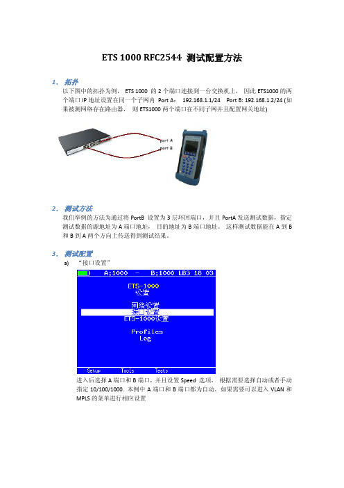
ETS 1000 RFC2544 测试配置方法1.拓扑以下图中的拓扑为例,ETS 1000 的2个端口连接到一台交换机上,因此ETS1000的两个端口IP地址设置在同一个子网内Port A:192.168.1.1/24 Port B: 192.168.1.2/24 (如果被测网络存在路由器,则ETS1000两个端口在不同子网并且配置网关地址)2.测试方法我们举例的方法为通过将PortB 设置为3层环回端口,并且PortA发送测试数据,指定测试数据的源地址为A端口地址,目的地址为B端口地址。
这样测试数据能在A到B 和B到A两个方向上传送得到测试结果。
3.测试配置a)“接口设置”进入后选择A端口和B端口,并且设置Speed 选项,根据需要选择自动或者手动指定10/100/1000. 本例中A端口和B端口都为自动。
如果需要可以进入VLAN和MPLS的菜单进行相应设置b)接口设置完成后进入“网络设置”菜单,如之前拓扑设置A 地址192.168.1.1 和B地址192.168.1.2 (如果被测网络中有路由器则地址应该在不同子网,并设置相应网关地址)c)进入“tools”菜单,设置环回端口,进入菜单选择端口B,设置Layer 为3。
此时,端口B将交换所受到数据包的源地址和目的地址,以便把测试数据发回到A 端口。
d)返回主界面进入“tests“菜单,进入RFC 2544 测试设置e)进入“设置“f)进入“topology“菜单,设置TX和RX port 都为Ag)返回上一级进入“Header“,设置Src MAC 和IP 为A,Dst MAC和IP 为Bh)返回上一级进入“Frames“并选择需要测试的帧大小i)返回上一级进入“Throughput“,设置传输的速率“Rate”,测试时间“Trial,S”RFC2544 推荐为60秒以上j)返回并进入“Latency”,设置测试时间“trial,s”并设置测试速率“Rates”为Throughput。
GODEX EZPi-1000 说明书

操作手册EZPi-1000Rev. B, 06.2009FCC COMPLIANCE STATEMENTFOR AMERICAN USERSThis equipment has been tested and found to comply with the limits for a CLASS A digital device, pursuant to Part 15 of the FCC Rules. These limits are designed to provide reasonable protection against harmful interference when the equipment is operated in a commercial environment. This equipment generates, uses, and can radiate radio frequency energy and, if not installed and used in accordance with the instructions, may cause harmful interference to radio communications. Operation of this equipment in a residential area is likely to cause harmful interference in which case the user will be required to correct the interference at own expense.EMS AND EMI COMPLIANCE STATEMENTFOR EUROPEAN USERSThis equipment has been tested and passed with the requirements relating to electromagnetic compatibility based on the standards EN 55022:1998+A1:2000+A2:2003, CISPR 22 , Class A EN 55024:1998+A1:2001+A2:2003, IEC 61000- 4 Series EN 61000-3-2 / 2000 & EN 61000-3-3 / 1995. The equipment also tested and passed in accordance with the European Standard EN55022 for the both Radiated and Conducted emissions limits.EZPi-1000 SERIESTO WHICH THIS DECLARATION RELATESIS IN CONFORMITY WITH THE FOLLOWING STANDARDSEN55022 : 1998,CLSPR 22, Class A / EN55024 : 1998IEC 61000-4 Serial / EN61000-3-2 : 2000 / EN 6100-3-3 : 1995 / CFR 47, Part 15/CISPR 22 3rd Edition : 1997, Class A / ANSI C63.4 : 2001 / CNS 13438 / IEC60950-1 : 2001 / GB4943 : 2001 / GB9254 : 1998 / GB17625.1 : 2003 /EN60950-1 : 2001CAUTIONDanger of explosion if battery is incorrectly replacedReplace only with the equivalent type recommended by the manufacture.Dispose of used batteries according to the manufacturer’s instructions.Only use with power supply adapter model: WDS060240P (9A).Changes or modifications not expressly approved by the party responsible for compliance could void the user's authority to operate the equipment.Specifications are subject to change without notice.Bitte die Sicherheitshinweise sorgfältig lesen und für später aufheben.1. Die Geräte nicht der Feuchtigkeit aussetzen.2. Bevor Sie die Geräte ans Stromnetz anschließen, vergewissern Sie Sich, dass dieSpannung des Geräts mit der Netzspannung übereinstimmt.3. Nehmen Sie das Gerät bei Überspannungen (Gewitter) vom Netz. Das Gerät könntesonst Schaden nehmen.4. Sollte versehentlich Flüssigkeit in das Gerät gelangen, so ziehen sofort denNetzstecker. Anderenfalls besteht die Gefahr eines lebensgefährlichen elektrischen Schlags.5. Wartungs- und Reparaturarbeiten dürfen aus Sicherheitsgründen nur vonautorisierten Personen durchgeführt werden.6. Bei Wartungs- und Reparaturarbeiten müssen die Sicherheitsvorschriften derzuständigen Berufsverbände und Behörden unbedingt eingehalten werden.7. Bei Verletzungen unbedingt den Arzt aufsuchen und die gegebenenfalls diezuständigen Stellen benachrichtigen. Unterlassung kann zum Verlust derVersicherungsleistungen führen.Please read the following instructions seriously.1. Keep the equipment away from humidity.2. Before you connect the equipment to the power outlet, please check the voltage of thepower source.3. Disconnect the equipment from the voltage of the power source to prevent possibletransient over voltage damage.4. Don’t pour any liquid to the equipment to avoid electrical shock.5. ONLY qualified service personnel for safety reason should open equipment.6. Don’t repair or adjust energized equipment alone under any circumstances. Someonecapable of providing first aid must always be present for your safety7. Always obtain first aid or medical attention immediately after an injury. Never neglectan injury, no matter how slight it seems.安全须知请仔细阅读以下说明。
CPE-1000-BGN用户手册_V1.0-20130701

服务 ........................................................................................................................... 40 2.5.1. WNMS ............................................................................................................... 40 2.5.2. 系统警报 ............................................................................................................ 40 2.5.3. SNMP Trap 设置 ................................................................................................ 42 2.5.4. SMTP 设置 ........................................................................................................ 42 2.5.5. SNMP ................................................................................................................. 43 2.5.6. 时钟/NTP ........................................................................................................... 43 2.5.7. SSH .................................................................................................................... 44 2.5.8. HTTP .................................................................................................................. 44
讯飞网维 信号特克 千兆以太网性能测试仪 说明书

SIGNAL TEK™Cable Performance T esterI Gigabit PerformanceQualification – Test toIEEE 802.3 standardsI Selectable PerformanceT esting – qualify performanceof Data, Voice over IP, andIP Video applicationsI Performs Gigabit Ethernetlink establishment test in10 secondsI Data Monitoring to detectintermittent network problemsI Smart Autotest Functiondetects the presence of theSIGNAL TEK remote, activenetwork device or open endedcable and automatically runsthe appropriate test suiteI Intuitive Graphical UserInterface for fast andeasy operationI Internal and USBData Storage –store 20,000 tests internallyor unlimited on USB driveI Prints Easy-to-Read Pass/Fail Qualification ReportsSIGNALTEK™– High-Performance Gigabit Ethernet TestingSIGNALTEK™is the most cost-effective Gigabit Ethernet cableAutotest key to initiate tests from the remote end for one personoperation2.8Љ(7.1cm) 1⁄4VGA Color Display with backlighting for use in low light conditionMulti-color LEDs indicate link status,loopback mode,10/100 and Gigabit device detection,Autotest pass/fail,and battery conditionEasy-to-navigate user interfaceCompact design and soft over-mold sides fit well into any sized handContext sensitive softkeysSingle button cable testingQuick navigation key returns to Job Manager screenSingle button push for active network testing and monitoring Port status function detects 10/100 or Gigabit Ethernet devicesDisplays result for last autotest via red or green LED indicationSIGNAL TEK ™Standard KitCatalog No. 33-974I1 SIGNALTEK ™Near-end and remote-end handset IDEAL INDUSTRIES, INC.03/06Printed in U.S.A.ISO 9001:2000 QMSNo. 33-974SIGNALTEK ™OptionalPower Adapter – 4010-00-0136DESCRIPTION CAT NUMBER SIGNALTEK™ Cable Performance Tester 33-974Replacement cable accessory kit –Contains all original cables in SIGNALTEK™ kit 1219-91-0003RJ45 to 8 head alligator clipK-7920OPTIONALUniversal (120-240V) AC-DC power adapter (1)4010-00-0136。
EXFO ETS 1000 RFC2544 测试配置方法
ETS 1000 RFC2544 测试配置方法1.拓扑以下图中的拓扑为例,ETS 1000 的2个端口连接到一台交换机上,因此ETS1000的两个端口IP地址设置在同一个子网内Port A:192.168.1.1/24 Port B: 192.168.1.2/24 (如果被测网络存在路由器,则ETS1000两个端口在不同子网并且配置网关地址)2.测试方法我们举例的方法为通过将PortB 设置为3层环回端口,并且PortA发送测试数据,指定测试数据的源地址为A端口地址,目的地址为B端口地址。
这样测试数据能在A到B 和B到A两个方向上传送得到测试结果。
3.测试配置a)“接口设置”进入后选择A端口和B端口,并且设置Speed 选项,根据需要选择自动或者手动指定10/100/1000. 本例中A端口和B端口都为自动。
如果需要可以进入VLAN和MPLS的菜单进行相应设置b)接口设置完成后进入“网络设置”菜单,如之前拓扑设置A 地址192.168.1.1 和B地址192.168.1.2 (如果被测网络中有路由器则地址应该在不同子网,并设置相应网关地址)c)进入“tools”菜单,设置环回端口,进入菜单选择端口B,设置Layer 为3。
此时,端口B将交换所受到数据包的源地址和目的地址,以便把测试数据发回到A 端口。
d)返回主界面进入“tests“菜单,进入RFC 2544 测试设置e)进入“设置“f)进入“topology“菜单,设置TX和RX port 都为Ag)返回上一级进入“Header“,设置Src MAC 和IP 为A,Dst MAC和IP 为Bh)返回上一级进入“Frames“并选择需要测试的帧大小i)返回上一级进入“Throughput“,设置传输的速率“Rate”,测试时间“Trial,S”RFC2544 推荐为60秒以上j)返回并进入“Latency”,设置测试时间“trial,s”并设置测试速率“Rates”为Throughput。
ZXECS 1000综合业务交换设备安装手册

ZXECS 1000 综合业务交换设备 安 装 手 册
中兴通讯股份有限公司
ZXECS 1000 综合业务交换设备安装手册
资料版本 产品版本
V1.0
策 编
划 著
责任编辑 * * * *
中兴通讯股份有限公司 地址:深圳市高新技术产业园科技南路中兴通讯大厦 网址: 邮编:518057 客户支持中心热线:(+86755)26770800 传真:(+86755)26770801 E-mail:800@ * * * * 800-830-1118
资料名称 产品版本 ZXECS 1000 综合业务交换设备安装手册 V1.0 资料版本
您单位安装该设备的时间 为了能够及时与您联系,请填写以下有关您的信息 姓名 邮编 电话 好 总体满意 工作指导 您对本资料 的评价 查阅方便 内容正确 内容完整 结构合理 图表说明 通俗易懂 详细说明 内容结构 内容详细 您对本资料的 改进建议 内容深度 表达简洁 增加图形 增加实例 增加 FAQ 其 他 较好 单位名称 单位地址 E-mail 一般 较差 差
本产品符合关于环境保护和人身安全方面的设计要求,产品的存放、使用和弃置应 遵照产品手册、相关合同或相关国法律、法规的要求进行。
- 1、下载文档前请自行甄别文档内容的完整性,平台不提供额外的编辑、内容补充、找答案等附加服务。
- 2、"仅部分预览"的文档,不可在线预览部分如存在完整性等问题,可反馈申请退款(可完整预览的文档不适用该条件!)。
- 3、如文档侵犯您的权益,请联系客服反馈,我们会尽快为您处理(人工客服工作时间:9:00-18:30)。
ETS-1000使用手册
2011年1月28日
EXFO的ETS-1000是一款经济高效的手持式以太网分析仪,服务提供商可使用该仪器进行下一代运营商以太网服务的开通和安装。
ETS-1000具有两个完全独立的测试端口,可支持以下接口:10/100/1000Base-T、1000Base-LX和1000Base-ZX。
下图为仪器外观:
一、基本功能介绍:
1、按F1进入“Setup”设置界面,如下图所示:
A)进入网络设置界面,可以设置各端口的IP、掩码、网关及DNS。
如下图所示:
B)进入接口设置界面,可以设置各端口的速率(10/100/100/Automatic)、Autoneg(自动协商On/Off)、MAC地址、VLAN及VLANID等参数。
如下图所示
C)ETS-1000设置为仪器基本设置,按出厂默认设置即可。
2、按F2进入“Tools”设置界面。
此界面可以测试以太网功能。
A)PING测试:Setup可以设置要PING的IP地址。
B)路由跟踪:可以测试IP 数据报访问目标所采取的路径。
C)DNS查找:输入网址,可以查找DNS
D)ARP监测:是否有ARP欺骗。
如下图:
E)TCP客户端:可测试访问网页是否正常。
TCP客户端设置:
F)电缆测试:可测试电缆是否正常。
G)环回:可以设置环回端口的参数(可选项为Off, 1层,2层,3层,4层环回)。
如下图所示:
3、按F3进入“Tests”设置界面。
A)RFC-2544标准测试:定义了四个测试:吞吐量,延迟,帧丢失率,背靠背。
如下图所示:(背靠背性能测试通过以最大帧速率发送突发传输流并测量无包丢失时的最大突发(burst)长度(总包数量)来测试被测设备的缓冲区容量。
)
进入设置界面如下图所示:
Topology参数:可以设置收发端端口。
若双仪表测试,则收发端为本端;若单仪表测试,则收发端为不同端口。
如下图所示:
Header参数:设置Src MAC和IP及Dst MAC和IP。
如下图所示:
Frames参数:可以设置测试帧大小。
如图所示:
剩下的Thoughput、Latency、Frame loss、Back-to-back按默认设置。
二、应用案例:
国土局省级专线MSTP升级项目采用双仪表方法。
接入方式见下图:
通过省国土厅仪表发送和接受测试数据,惠州国土局仪表设置为2层环回。
如下图所示:省国土厅仪表需在“Tests”—>“RFC-2544设置”菜单下的“Topology”设置发送和接受端口;在“Header”菜单下设置Src MAC及IP,Dst MAC及IP。
测试开始后,接受的仪表可以看到发送及接受数据包及测试项目。
如下图所示:
环回的仪表在“环回”菜单下可以看到发送和接受的数据包。
如下图所示:
测试完成后按F4进入“Results”界面的F2“Save”键,可以把测试结果储存到仪表中。
三、报告下载:
在仪表LAN口设置IP及掩码,连接的电脑设置成和仪表LAN同一网段的IP。
1、在IE输入LAN口的IP即可连接登记表。
如下图所示:
如果有多条记录,则需在“Results”界面选择要查看的结果,按F3“Load ”,即可以IE查看结果。
如下所示:。