viewing angle 080611
Kingbright 蓝色LED灯的数据手册说明书
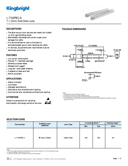
Part NumberEmitting Color (Material)Lens TypeIv (mcd) @ 20mA [2] Viewing Angle [1]Min. Typ. 2θ1/2L-7104PBC-A■ Blue (InGaN)Water Clear 400 30°900DESCRIPTIONSzThe Blue source color devices are made with InGaN on SiC Light Emitting Diodez Electrostatic discharge and power surge could damage the LEDsz It is recommended to use a wrist band oranti-electrostatic glove when handling the LEDs z All devices, equipments and machineries must be electrically groundedFEATURESzLow power consumptionz Popular T-1 diameter package z General purpose leads z Reliable and ruggedz Long life - solid state reliability z Available on tape and reel z RoHS compliantAPPLICATIONSz Status indicator z Illuminatorz Signage applicationsz Decorative and entertainment lightingzCommercial and residential architectural lightingATTENTIONObserve precautions for handlingelectrostatic discharge sensitive devicesPACKAGE DIMENSIONSL-7104PBC-AT-1 (3mm) Solid State LampSELECTION GUIDENotes:1. θ1/2 is the angle from optical centerline where the luminous intensity is 1/2 of the optical peak value.2. Luminous intensity / luminous flux: +/-15%.3. Luminous intensity value is traceable to CIE127-2007 standards.Notes:1. All dimensions are in millimeters (inches).2. Tolerance is ±0.25(0.01") unless otherwise noted.3. Lead spacing is measured where the leads emerge from the package.4. The specifications, characteristics and technical data described in the datasheet are subject to change without prior notice.ABSOLUTE MAXIMUM RATINGS at T A =25°CELECTRICAL / OPTICAL CHARACTERISTICS at T A =25°CNotes:1. 1/10 Duty Cycle, 0.1ms Pulse Width.2. 2mm below package base.3. 5mm below package base.4. Relative humidity levels maintained between 40% and 60% in production area are recommended to avoid the build-up of static electricity – Ref JEDEC/JESD625-A and JEDEC/J-STD-033.Notes:1. The dominant wavelength (λd) above is the setup value of the sorting machine. (Tolerance λd : ±1nm. )2. Forward voltage: ±0.1V.3. Wavelength value is traceable to CIE127-2007 standards.4. Excess driving current and / or operating temperature higher than recommended conditions may result in severe light degradation or premature failure.ParameterSymbol Value Unit Power Dissipation P D 120 mW Reverse Voltage V R 5 V Junction Temperature T j 125 °C Operating Temperature T op -40 to +85 °C Storage Temperature T stg -40 to +85°C DC Forward Current I F 30 mA Peak Forward CurrentI FM [1]100 mA Electrostatic Discharge Threshold (HBM) -1000VLead Solder Temperature [2] 260°C For 3 Seconds Lead Solder Temperature [3]260°C For 5 SecondsParameterSymbol Emitting ColorValue Unit Typ. Max. Wavelength at Peak Emission I F = 20mA λpeak Blue 468 - nm Dominant Wavelength I F = 20mA λdom [1] Blue 465 - nm Spectral Bandwidth at 50% Φ REL MAX I F = 20mA Δλ Blue 21 - nm CapacitanceC Blue 100 - pF Forward Voltage I F = 20mA V F [2] Blue 3.2 4 V Reverse Current (V R = 5V)I RBlue-10uATECHNICAL DATABLUERECOMMENDED WAVE SOLDERING PROFILENotes:1. Recommend pre-heat temperature of 105°C or less (as measured with a thermocoupleattached to the LED pins) prior to immersion in the solder wave with a maximum solder bath temperature of 260°C2. Peak wave soldering temperature between 245°C ~ 255°C for 3 sec (5 sec max).3. Do not apply stress to the epoxy resin while the temperature is above 85°C.4. Fixtures should not incur stress on the component when mounting and during soldering process.5. SAC 305 solder alloy is recommended.6. No more than one wave soldering pass.PACKING & LABEL SPECIFICATIONSPRECAUTIONSStorage conditions1. Avoid continued exposure to the condensing moisture environment and keep the product away from rapid transitions in ambient temperature.2. LEDs should be stored with temperature ≤ 30°C and relative humidity < 60%.3. Product in the original sealed package is recommended to be assembled within 72 hours of opening. Product in opened package for more than a week should be baked for 30 (+10/-0) hours at 85 ~ 100°C.2. When soldering wires to the LED, each wire joint should be separately insulated with heat-shrink tube to prevent short-circuit contact. Do not bundle both wires in one heat shrink tube to avoid pinching the LED leads. Pinching stress on the LED leads may damage the internal structures and cause failure.3. Use stand-offs (Fig.1) or spacers (Fig.2) to securely position the LED above the PCB.4. Maintain a minimum of 3mm clearance between the base of the LED lens and the first lead bend (Fig. 3 ,Fig. 4).5. During lead forming, use tools or jigs to hold the leads securely so that the bending force will not be transmitted to the LED lens and its internal structures. Do not perform lead forming once the component has been mounted onto the PCB. (Fig. 5 )LED Mounting Method1. The lead pitch of the LED must match the pitch of the mounting holes on the PCB during component placement.Lead-forming may be required to insure the lead pitch matches the hole pitch.Refer to the figure below for proper lead forming procedures.Note 1-3: Do not route PCB trace in the contact area between the leadframe and the PCB to prevent short-circuits." ○" Correct mounting method " x " Incorrect mounting methodLead Forming Procedures1. Do not bend the leads more than twice. (Fig. 6 )2. During soldering, component covers and holders should leaveclearance to avoid placing damaging stress on the LED duringsoldering.(Fig. 7)3. The tip of the soldering iron should never touch the lens epoxy.4. Through-hole LEDs are incompatible with reflow soldering.5. If the LED will undergo multiple soldering passes or face otherprocesses where the part may be subjected to intense heat,please check with Kingbright for compatibility.PRECAUTIONARY NOTES1. The information included in this document reflects representative usage scenarios and is intended for technical reference only.2. The part number, type, and specifications mentioned in this document are subject to future change and improvement without notice. Before production usage customer should refer tothe latest datasheet for the updated specifications.3. When using the products referenced in this document, please make sure the product is being operated within the environmental and electrical limits specified in the datasheet. Ifcustomer usage exceeds the specified limits, Kingbright will not be responsible for any subsequent issues.4. The information in this document applies to typical usage in consumer electronics applications. If customer's application has special reliability requirements or have life-threateningliabilities, such as automotive or medical usage, please consult with Kingbright representative for further assistance.5. The contents and information of this document may not be reproduced or re-transmitted without permission by Kingbright.6. All design applications should refer to Kingbright application notes available at /application_notes。
欧司朗LED详解

LW W5AMGolden DRAGON PlusLead (Pb) Free Product - RoHS Compliant Released2011-07-291Besondere Merkmale•Gehäusetyp: weißes SMD Gehäuse, klare Silikonlinse, Chip level conversion•Typischer Lichtstrom: 100 lm bei 350 mA und bis zu 240 lm bei 1 A•Besonderheit des Bauteils: hocheffiziente Lichtquelle bei geringem Platzbedarf •Farbort: x = 0,33, y = 0,33 nach CIE 1931 (weiß)•typische Farbtemperatur: 5600 K •Farbwiedergabeindex: 80•Abstrahlwinkel: 170°•Technologie: ThinGaN•optischer Wirkungsgrad: 130 lm/W bei 100 mA•Gruppierungsparameter: Lichtstrom, Farbort •Verarbeitungsmethode: für SMT-Bestücktechniken geeignet •Lötmethode: Reflow Löten•Vorbehandlung: nach JEDEC Level 2•Gurtung: 24-mm Gurt mit 200/Rolle, ø180 mm oder 1200/Rolle, ø330 mm (auf Anfrage)•ESD-Festigkeit: ESD-sicher bis 8 kV nach JESD22-A114-D•Erweiterte Korrosionsfestigkeit: Details siehe Seite 11Anwendungen•Hinterleuchtung (Werbebeleuchtung, Allgemeinbeleuchtung)•Leselampen•Ersatz von Kleinst-Glühlampen•Fassadenbeleuchtung im Innen- und Außenbereich•Dekorative Beleuchtung •StraßenbeleuchtungFeatures•package: white SMD package, clear silicone lens, chip level conversion•typical Luminous Flux: 100 lm at 350 mA and up to 240 lm at 1 A•feature of the device: high efficient lightsource at low space•color coordinates: x = 0.33, y = 0.33 acc. to CIE 1931 (white)•typ. color temperature: 5600 K •color reproduction index: 80•viewing angle: 170°•technology: ThinGaN•optical efficiency: 130 lm/W at 100 mA •grouping parameter: luminous flux, color coordinates•assembly methods: suitable for SMT assembly methods•soldering methods: reflow soldering •preconditioning: acc. to JEDEC Level 2•taping: 24 mm tape with 200/reel, ø180 mm or 1200/reel, ø330 mm (on request)•ESD-withstand voltage: up to 8 kV acc. to JESD22-A114-D•Superior Corrosion Robustness: details see page 11Applications•backlighting (illuminated advertising, general lighting)•reading lamps•substitution of micro incandescent lamps•indoor and outdoor commercial and residential architectural lighting•decorative and entertainment lighting •street lighting2011-07-292Anm.:Die oben genannten Typbezeichnungen umfassen die bestellbaren Selektionen. Diese bestehen aus wenigenHelligkeitsgruppen (siehe Seite 6 für nähere Informationen). Es wird nur eine einzige Helligkeitsgruppe pro Gurt geliefert. Z.B.: LW W5AM -KXLX-5K8L bedeutet, dass auf dem Gurt nur eine der Helligkeitsgruppen KX, KY, KZ oder LX enthalten ist.Um die Liefersicherheit zu gewährleisten, können einzelne Helligkeitsgruppen nicht bestellt werden.Gleiches gilt für die Farben, bei denen Farbortgruppen gemessen und gruppiert werden. Pro Gurt wird nur eine Farbortgruppe geliefert. Z.B.: LW W5AM-KXLX -5K8L bedeutet, dass auf dem Gurt nur eine der Farbortgruppen -5K bis -8L enthalten ist (siehe Seite 5 für nähere Information).Um die Liefersicherheit zu gewährleisten, können einzelne Farbortgruppen nicht bestellt werden.Note:The above Type Numbers represent the order groups which include only a few brightness groups (see page 6for explanation). Only one group will be shipped on each reel (there will be no mixing of two groups on each reel). E.g. LW W5AM -KXLX-5K8L means that only one group KX, KY, KZ or LX will be shippable for any one reel.In order to ensure availability, single brightness groups will not be orderable.In a similar manner for colors where chromaticity coordinate groups are measured and binned, single chromaticity coordinate groups will be shipped on any one reel. E.g. LW W5AM-KXLX -5K8L means that only 1 chromaticity coordinate group -5K to -8L will be shippable on each reel (see page 5 for explanation). In order to ensure availability, single chromaticity coordinate groups will not be orderable.Bestellinformation Ordering Information TypTypeEmissions- farbeColor of EmissionLichtstrom 1) Seite 19Luminous Flux 1) page 19I F = 350 mA ΦV (mlm)Lichtstärke 2) Seite 19LuminousIntensity 2) page 19I F = 350 mA I V (mcd)BestellnummerOrdering CodeLW W5AM-KXLX-5K8L LW W5AM-KYLX-6K7Lwhite71.000 ... 130.000 82.000 ... 130.00025.100 (typ.) 26.500 (typ.)Q65110A9850 Q65110A95292011-07-293Maximum Ratings Bezeichnung ParameterSymbol SymbolWert Value Einheit Unit BetriebstemperaturOperating temperature range T op – 40 … + 125°C LagertemperaturStorage temperature range T stg – 40 … + 125°C Sperrschichttemperatur Junction temperatureT j135°C Sperrschichttemperatur für Kurzzeitanwendungen* Junction temperature for short term application*T j 175*°C Durchlassstrom (min.) Forward current (max.) (T S =25°C)I F I F1001000mA mA Stoßstrom Surge currentt ≤ 10 µs, D = 0.005, T S =25°C I FM2500mASperrspannung Reverse voltage (T S =25°C)V Rnot designed for reverse operationV *Auch bei höchsten Temperaturen zeigt der LED Chip sehr gute Leistungsmerkmale, aber es kann eine leichte Verfärbung des Gehäuses auftreten. Die mittlere Lebensdauer bei T j = 175°C beträgt 100h.*The LED chip exhibits excellent performance but slight package discoloration occurs at highest temperatures. Exemplary median lifetime for T j = 175°C is 100h.2011-07-294Characteristics (T S = 25 °C)Bezeichnung ParameterSymbol Symbol Wert Value Einheit Unit Farbkoordinate x nach CIE 19313) Seite 19(typ.)Chromaticity coordinate x acc. to CIE 19313) page 19I F = 350 mAx0.33–Farbkoordinate y nach CIE 19313) Seite 19(typ.)Chromaticity coordinate y acc. to CIE 19313) page 19I F = 350 mAy 0.33–Abstrahlwinkel bei 50 % ΙV (Vollwinkel)(typ.) Viewing angle at 50 % ΙV 2ϕ170Grad deg.Durchlassspannung 4) Seite 19)(min.) Forward voltage 4) page 19(typ.) I F = 350 mA (max.)V F V F V F2.73.23.7V V VSperrstromReverse current (max.)I Rnot designed for reverse operation µAWärmewiderstand Thermal resistance Sperrschicht/Lötpad (typ.) Junction/soldering point(max.)R th JS R th JS6.511*K/W K/W*R th (max) basiert auf statistischen Werten R th (max) is based on statistic values2011-07-295Farbortgruppen 5) Seite 195) page 19Gruppe Group Cx Cy Gruppe Group Cx Cy 5K0.2960.2597K0.3300.3100.2910.2680.3300.3300.3100.2970.3380.3420.3130.2840.3520.3445L 0.2910.2687L0.3300.3300.2850.2790.3300.3470.3070.3120.3470.3710.3100.2970.3450.3526K 0.3130.2848K0.3520.3440.3100.2970.3380.3420.3300.3300.3640.3800.3300.3100.3600.3576L 0.3100.2978L0.3450.3520.3070.3120.3470.3710.3300.3470.3670.4010.3300.3300.3640.3802011-07-296Gruppenbezeichnung auf Etikett Group Name on Label Beispiel: KX-5K Example: KX-5K Helligkeits-Gruppierungsschema Brightness Groups Helligkeitsgruppe Brightness Group Lichtstrom 1) Seite 19Luminous Flux 1) page 19 ΦV (mlm)Lichtstärke 2) Seite 19Luminous Intensity 2) page 19 I V (mcd)KX KY KZ LX71.000 ...82.000 82.000 ...97.000 97.000 ...112.000 112.000 ...130.00019.100 (typ.) 22.400 (typ.) 26.100 (typ.) 30.250 (typ.)Anm.:Die Standardlieferform von Serientypen beinhaltet eine Familiengruppe. Diese besteht auswenigen Helligkeitsgruppen. Einzelne Helligkeitsgruppen sind nicht bestellbar.Note:The standard shipping format for serial types includes a family group of only a few individualbrightness groups. Individual brightness groups cannot be ordered.Helligkeitsgruppe Brightness Group FarbortgruppeChromaticity Coordinate Group KX5KAnm.:In einer Verpackungseinheit / Gurt ist immer nur eine Helligkeitsgruppe enthalten.Note:No packing unit / tape ever contains more than one brightness group.2011-07-297Relative spektrale Emission 2) Seite 19 Relative Spectral Emission 2) page 19V(λ) = spektrale Augenempfindlichkeit / Standard eye response curve Φrel =Radiation Characteristic 2) page 19 Ιrel = f (ϕ); T S = 25 °C2011-07-298Durchlassstrom 2)4) Seite 19 Forward Current 2)4) page 19 I F = f (V F ); T S = 25 °Csolid line: specified DC-rangeRelative Farbortverschiebung 2) Seite 17Relative Chromaticity Coordinate Shift 2) page 17 ∆x, ∆y = f (I); T = 25 °CRelative Lichtstrom 2) Seite 19Relative Luminous Flux 2) page 19 ΦV /ΦV (350 mA) = f (I F ); T S = 25 °C2011-07-299Relative Vorwärtsspannung 2)4) Seite 19 Relative Forward Voltage 2)4) page 19∆V= V - V (25 °C) = f (T ); I = 350 mARelative Farbortverschiebung 2) Seite 19Relative Chromaticity Coordinate Shift 2) page 19 ∆x, ∆y = f (T); I F = 350 mA Relative Lichtstrom 2) Seite 19Relative Luminous Flux 2) page 19 ΦV /ΦV (25 °C) = f (T); I = 350 mA2011-07-2910Maximal zulässiger Durchlassstrom Max. Permissible Forward Current I FZulässige Impulsbelastbarkeit I F = f (t p ) Permissible Pulse Handling Capability Duty cycle D = parameter, T= 25 °CZu Lebensdauerangaben sieheApplikationsschrift:“Reliability of the DRAGON Product Family“For life time information please refer to application note “Reliability of the DRAGON Product Family“Zulässige Impulsbelastbarkeit I F = f (t p ) Permissible Pulse Handling Capability Duty cycle D = parameter, T S = 85 °C2011-07-2911Maßzeichnung 5) Seite 195) page 19Note:LED is protected by ESD device which is connected in parallel to LED-Chip.Kathodenkennung:Markierung Cathode mark:mark Gewicht / Approx. weight:250 mgKorrosionsfestigkeit besser als EN 60068-2-60 (method 4): mit erweitertem Korrosionstest: 40°C / 90%rh / 15pp m H 2S / 336h Corrosion robustness better than EN 60068-2-60 (method 4): with enhanced corrosion test: 40°C / 90%rh / 15ppm H 2S / 336hGurtung / Polarität und Lage5) Seite 19Verpackungseinheit200/Rolle, ø180 mmoder 1200/Rolle, ø330 mm (auf Anfrage) Method of Taping / Polarity and Orientation5) page 19Packing unit200/reel, ø180 mmor 1200/Rolle, ø330 mm (on request)2011-07-29122011-07-2913Empfohlenes Lötpaddesign 5) Seite 19Reflow Löten Recommended Solder Pad 5) page 19Reflow SolderingLötbedingungen Vorbehandlung nach JEDEC Level 2 Soldering Conditions Preconditioning acc. to JEDEC Level 2 Reflow Lötprofil für bleifreies Löten(nach J-STD-020C)Reflow Soldering Profile for lead free soldering(acc. to J-STD-020C)Anm.:Das Gehäuse ist für Ultraschallreinigung nicht geeignetNote:Package not suitalbe for ultra sonic cleaning2011-07-29142011-07-2915GurtverpackungTape dimensions in mm (inch)WP 0P 1P 2D 0EF4 ± 0.1 (0.157 ± 0.004)12 ± 0.1 (0.472 ± 0.004) 2 ± 0.1 (0.079 ± 0.004) 1.5 + 0.1 (0.059 + 0.004) 1.75 ± 0.1 (0.069 ± 0.004)11.5 ± 0.1(0.453 ± 0.004)Reel dimensions in mm (inch)A W N min W 1W 2 max 180 (7)24 (0.945)60 (2.362)24.4 + 2 (0.961 + 0.079)30.4 (1.197)330 (13)24 (0.945)60 (2.362)24.4 + 2 (0.961 + 0.079)30.4 (1.197)24+ 0.3– 0.12011-07-2916Trockenverpackung und MaterialienAnm.:Feuchteempfindliche Produkte sind verpackt in einem Trockenbeutel zusammen mit einem Trockenmittel undeiner FeuchteindikatorkarteBezüglich Trockenverpackung finden Sie weitere Hinweise im Internet und in unserem Short Form Catalog im Kapitel “Gurtung und Verpackung” unter dem Punkt “Trockenverpackung”. Hier sind Normenbezüge, unter anderem ein Auszug der JEDEC-Norm, enthalten.Note:Moisture-senisitve product is packed in a dry bag containing desiccant and a humidity card.Regarding dry pack you will find further information in the internet and in the Short Form Catalog in chapter “Tape and Reel” under the topic “Dry Pack”. Here you will also find the normative references like JEDEC.Kartonverpackung und MaterialienDimensions of transportation box in mm (inch)Breite / WidthLänge / lengthHöhe / height 200 ±5 (7,874 ±0,1968±)200 ±5 (7,874 ±0,1968)42 ±5 (1,65 ±0,1968)352 ±5 (13,858 ±0,1968±)352 ±5 (13,858 ±0,1968)42 ±5 (1,65 ±0,1968)2011-07-2917Wegen der Streichung der LED aus der IEC 60825 erfolgt die Bewertung der Augensicherheit nach dem Standard CIE S009/E:2002 / IEC 62741("photobiological safety of lamps and lamp systems")Im Risikogruppensystem dieser CIE- Norm erfüllen die in diesem Datenblatt angegebenen LED die "moderate risk"- Gruppe (die die sich im "sichtbaren" Spektralbereich auf eine Expositionsdauer von 0,25s bezieht). Unter realen Umständen (für Expositionsdauer, Augenpupille, Betrachtungsabstand) geht damit von diesen Bauelementen keinerlei Augengefährdung aus.Grundsätzlich sollte jedoch erwähnt werden, dass intensive Lichtquellen durch ihre Blendwirkung ein hohes sekundäres Gefahrenpotenzial besitzen. Wie nach dem Blick in andere helle Lichtquellen (z.B. Autoscheinwerfer) auch, können temporär eingeschränktes Sehvermögen und Nachbilder je nach Situation zu Irritationen, Belästigungen, Beeinträchtigungen oder sogar Unfällen führen.Due to the cancellation of the LED from IEC 60825, the evaluation of eye safety occurs according to the standard CIE S009/E:2002 / IEC 62741 ("photobiological safety of lamps and lamp systems").Within the risk grouping system of this CIE standard, the LEDs specified in this data sheet fall into the "moderate risk" group (relating to devices in the visible spectrum with an exposure time of 0.25s). Under real circumstances (for exposure time, eye pupils, observation distance), it is assumed that no endangerment to the eye exists from these devices.As a matter of principle, however, it should be mentioned that intense light sources have a high secondary exposure potential due to their blinding effect. As is also true when viewing other bright light sources (e.g. headlights), temporary reduction in visual acuity and afterimages can occur, leading to irritation, annoyance, visual impairment, and even accidents, depending on the situation.Revision History:2011-07-29 Previous Version:2010-08-26Page Subjects (major changes since last revision)Date of change 10Diagram Permissible Pulse Handling Capability changed 2008-02-274Thermal resistance R th JS (typ.) added2009-04-224OS-IN-2009-020 (Forward voltage max reduced)2009-06-1611Package Outlines and Method of Taping / Polarity and Orientation updated2009-06-192, 6ordering code changed 2009-10-191typical Luminous Flux updated 2009-10-191, 4optical efficiency updated 2009-10-191, 12additional information 2010-03-01all data sheet released 2010-03-172, 6ordering code updated2010-04-2817Eye safety information corrected 2010-08-262Q-Number deleted2011-07-292011-07-2918Attention please!The information describes the type of component and shall not be considered as assured characteristics.Terms of delivery and rights to change design reserved. Due to technical requirements components may contain dangerous substances. For information on the types in question please contact our Sales Organization. If printed or downloaded, please find the latest version in the Internet.PackingPlease use the recycling operators known to you. We can also help you – get in touch with your nearest sales office. By agreement we will take packing material back, if it is sorted. You must bear the costs of transport. For packing material that is returned to us unsorted or which we are not obliged to accept, we shall have to invoice you for any costs incurred.Components used in life-support devices or systems must be expressly authorized for such purpose! Critical components 6) page 19 may only be used in life-support devices or systems 7) page 19 with the express written approval of OSRAM OS.Patent List Patent 6 066 861 US 6 277 301 US 6 245 2592011-07-2919Fußnoten:1)Helligkeitswerte werden während eines Strompulses einer typischen Dauer von 25 ms, mit einer internen Reproduzierbarkeit von +/- 8 % und einer erweiterten Messunsicherheit von +/- 11 % gemessen (gemäß GUM mit Erweiterungsfaktor k = 3).2)Wegen der besonderen Prozessbedingungen bei der Herstellung von LED können typische oder abgeleitete technische Parameter nur aufgrund statistischer Werte wiedergegeben werden. Diese stimmen nicht notwendigerweise mit den Werten jedes einzelnen Produktes überein, dessen Werte sich von typischen und abgeleiteten Werten oder typischen Kennlinien unterscheiden können. Falls erforderlich, z.B. aufgrund technischer Verbesserungen, werden diese typischen Werte ohne weitere Ankündigung geändert.3)Farbkoordinaten werden während eines Strompulses einer typischen Dauer von 25 ms, mit einer internen Reproduzierbarkeit von +/- 0,005 und einer erweiterten Messunsicherheit von +/- 0,01 gemessen (gemäß GUM mit Erweiterungsfaktor k = 3).4)Vorwärtsspannungen werden während eines Strompulses einer typischen Dauer von 8 ms, mit einer internen Reproduzierbarkeit von +/- 0,05 V und einer erweiterten Messunsicherheit von +/- 0,1 V gemessen (gemäß GUM mit Erweiterungsfaktor k=3).5)Maße werden wie folgt angegeben: mm (inch) 6)Ein kritisches Bauteil ist ein Bauteil, das in lebenserhaltenden Apparaten oder Systemen eingesetzt wird und dessen Defekt voraussichtlich zu einer Fehlfunktion dieses lebenserhaltenden Apparates oder Systems führen wird oder die Sicherheit oder Effektivität dieses Apparates oder Systems beeinträchtigt.7)Lebenserhaltende Apparate oder Systeme sind für (a) die Implantierung in den menschlichen Körper oder(b) für die Lebenserhaltung bestimmt.Falls sie versagen, kann davon ausgegangen werden, dass die Gesundheit und das Leben des Patienten in Gefahr ist.Published byOSRAM Opto Semiconductors GmbH Leibnizstrasse 4, D-93055 Regensburg © All Rights Reserved.Remarks:1)Brightness values are measured during a current pulse of typical 25 ms, with an internal reproducibility of +/- 8 % and an expanded uncertainty of +/- 11 % (acc. to GUM with a coverage factor of k = 3). 2)Due to the special conditions of the manufacturing processes of LED, the typical data or calculated correlations of technical parameters can only reflect statistical figures. These do not necessarily correspond to the actual parameters of each single product, which could differ from the typical data and calculated correlations or the typical characteristic line. If requested, e.g. because of technical improvements, these typ. data will be changed without any further notice.3)Chromaticity coordinates are measured during a current pulse of typical 25 ms, with an internal reproducibility of +/- 0,005 and an expanded uncertainty of +/- 0,01 (acc. to GUM with a coverage factor of k = 3).4)The forward voltage is measured during a current pulse of typical 8 ms, with an internal reproducibility of +/- 0,05 V and an expanded uncertainty of +/- 0,1 V (acc. to GUM with a coverage factor of k=3).5)Dimensions are specified as follows: mm (inch).6)A critical component is a component used in a life-support device or system whose failure can reasonably be expected to cause the failure of that life-support device or system, or to affect its safety or the effectiveness of that device or system.7)Life support devices or systems are intended (a) to be implanted in the human body, or(b) to support and/or maintain and sustain human life. If they fail, it is reasonable to assume that the health and the life of the user may be endangered.。
资源三号卫星影像购买元数据说明

北京揽宇方圆资源三号卫星影像元数据说明(一) 文件自包含信息 <generalHeader fileName="xxx.xml" fileVersion="1.0"> <itemName>Sensor Corrected Product</itemName> <mission>SURVEY</mission> <!‐‐ 取值: 测绘任务:SURVEY 资源模式:Resource 应急模式:Emergency ‐‐> <destination>User</destination> <generationTime>2007‐12‐02T20:05:58.000000</generationTime> <referenceDocument> </referenceDocument> <!—非必要‐‐> <remark></remark> <!—非必要‐‐> </generalHeader> <productComponents> <metadata> <file> <!‐‐ 元数据文件 ‐‐> <location> <host>.</host> <path>.</path> <!—元数据文件所在的服务器,如果在本地,该字段可为空‐‐> <!—元数据文件所在的路径‐‐> <filename>ZY3_01a_synbavp_880176_20120523_104436_0008_SASMAC_CHN_sec_rel_ 001_1206077058.xml</filename> <!—元数据文件名‐‐> </location> </file> </metadata> <imageData layerIndex="1"> <!‐‐ 影像数据文件 ‐‐> <file> <location> <host>.</host> <path>IMAGEDATA</path> <filename>ZY3_01a_synbavp_880176_20120523_104436_0008_SASMAC_CHN_sec_rel_00 1_1206077058.tif</filename></location></file></imageData><rpcFile> <file> <!‐‐ RPC 文件‐‐> <location> <host>.</host><path>.</path> <filename>ZY3_01a_synbavp_880176_20120523_104436_0008_SASMAC_CHN_sec_rel_00 1_1206077058_rpc.txt</filename></location></file> </rpcFile> <browseImage> <file> <!‐‐ 浏览图文件 ‐‐> <location><host>.</host><path>PREVIEW</path> <filename>ZY3_01a_synbavp_880176_20120523_104436_0008_SASMAC_CHN_sec_rel_001_1206077058_pre.jpg</filename></location></file></browseImage> <thumbImage> <file><!‐‐ 拇指图文件 ‐‐> <location><host>.</host><path>PREVIEW</path><filename>ZY3_01a_synbavp_880176_20120523_104436_0008_SASMAC_CHN_sec_rel_00 1_1206077058_ico.jpg</filename></location></file></thumbImage><geoRangeFile> <file><!‐‐ 范围 ShapeFile 文件‐‐> <location><host>.</host><path>PREVIEW</path><filename>ZY3_01a_synbavp_880176_20120523_104436_0008_SASMAC_CHN_sec_rel_00 1_1206077058_Geo.shp</filename></location></file> </geoRangeFile></productComponents>(二) 产品信息 <productInfo><!‐‐ 卫星标识‐‐><SatelliteID>ZY3‐1</SatelliteID> <!‐‐接收站标识 MYN 为密云,KAS 为喀什,SAY 为三亚,… ‐‐><ReceiveStationID>SAY</ReceiveStationID> <!‐‐ 传感器标识:FWD :资源三号前视相机;NAD :资源三号下视相机;BWD :资源三号 后视相机;MUX :资源三号多光谱相机;TLC :资源三号三线阵相机(包括前、下后)‐‐> <SensorID>BWD</SensorID><!‐‐时间类型,北京时间:BJ,…‐‐><DefaultTimeType>BJ</DefaultTimeType><!—数据获取时间,精确到小时‐‐><AcquisitionTime>2012060715</ AcquisitionTime ><!‐‐产品生产时间,精确到小时‐‐><ProductTime>2012060715</ProductTime><!‐‐轨道圈号‐‐><OrbitID>2061</OrbitID><!‐‐轨道类型:GPS:GPS轨道; DGPS:双频 GPS精化后轨道‐‐><OrbitType>GPS</OrbitType><!‐‐姿态类型:星上 STAR;精确 STAR‐precise;或则其他别的什么…‐‐><AttitudeType>STAR</AttitudeType><!—数据生产方式,取值XXX-YYY七个字符形式,具体取值见下表-->raw sec gec ggc gtc tru 未作任何几何纠正传感器校正顾及椭球的几何纠正使用控制点的几何纠正带地形的几何纠正(即正射纠正)真正射影像纠正xxx 3字母几何处理方式raw rel abs ter 未作辐射校正相对辐射校正绝对辐射校正(大气,BRDF 等)地形辐射校正yyy 3字母辐射处理方式<ProduceType>STANDARD</ProduceType><!‐‐景号‐‐><SceneID>157921</SceneID><!‐‐产品数据 ID(流水号)‐‐><ProductID>1206077058</ProductID><!‐‐产品级别:SC\GEC\eGEC\GTC\DOM‐‐><ProductLevel>SensorCorrected</ProductLevel><!‐‐谱段模式: P(全色);M(多光谱);T(热红外);H(高光谱)‐‐><BandModel>H</BandModel><!‐‐产品波段: 下视相机\前视相机\后视相机:1; 多光谱相机:1,2,3,4 ‐‐><Bands>1,2,3</Bands><!‐‐融合方式: BGR(融合产品真彩);GRN(融合产品伪彩);BGRN(融合产品全波段)‐‐> <FUSMethod> </FUSMethod><!‐‐分景模式:N(:标准景; D:双倍景; T:三倍景; S:条带影像‐‐><SceneMode>N</SceneMode><!‐‐景 Path‐‐><ScenePath>727</ScenePath><!‐‐景 Row‐‐><SceneRow>102</SceneRow><!‐‐条带景数目‐‐><SceneCount>1</SceneCount><!‐‐景漂移‐‐><SceneShift>0</SceneShift><TimeStamp><!‐‐时间类型‐‐><TimeType>BJ</TimeType><!‐‐产品起始时间‐‐><StartTime>2011‐09‐09 17:56:02.00000000</StartTime> <!‐‐产品终止时间‐‐><EndTime>2011‐09‐09 17:56:02.000000000</EndTime><!‐‐产品中间时间‐‐><CenterTime>2011‐09‐09 17:56:02.0000</CenterTime><!‐‐各扫描行时间间隔,单位秒‐‐><Interval>0.000499991518154275</Interval></TimeStamp><!‐‐产品分辨率‐‐><ImageGSD><Line>3.60</Line><Sample>3.60</Sample> </ImageGSD> <!—列(沿轨)分辨率‐‐> <!—行(垂轨)分辨率‐‐><!‐‐像素字节数: u表示无符号,i表示整形,f表示浮点,数字表示字节数目‐‐> <PixelByte>ui16</PixelByte><!‐‐产品行数‐‐><WidthInPixels>0</WidthInPixels><!‐‐产品列数‐‐><HeightInPixels>0</HeightInPixels><!‐‐产品宽度: 以 M为单位‐‐><WidthInMeters>0</WidthInMeters><!‐‐产品高度: 以 M为单位‐‐><HeightInMeters>0</HeightInMeters><!‐‐产品所在地区‐‐><RegionName>XXX</RegionName><!‐‐云覆盖量‐‐><CloudPercent>0</CloudPercent><!‐‐相机侧视角‐‐><RollViewingAngle>0.0</RollViewingAngle><!‐‐相机前后视角‐‐><PitchViewingAngle>0.0</PitchViewingAngle><!‐‐卫星平台滚动角‐‐><RollSatelliteAngle>0.0</RollSatelliteAngle><!‐‐卫星平台平均俯仰角‐‐><PitchSatelliteAngle>0.0</PitchSatelliteAngle><!‐‐卫星平台平均航偏角‐‐><YawSatelliteAngle>0.0</YawSatelliteAngle><!‐‐卫星平台侧摆角‐‐><SwingSatelliteAngle>0.0</SwingSatelliteAngle><!‐‐太阳方位角‐‐><SolarAzimuth>345.327423</SolarAzimuth><!‐‐太阳高度角‐‐><SolarZenith>22.902334</SolarZenith><!‐‐卫星方位角‐‐><SatelliteAzimuth>0.0</SatelliteAzimuth><!‐‐卫星高度角‐‐><SatelliteZenith>0.0</SatelliteZenith><!‐‐增益模式‐‐><GainMode>0.000000</GainMode><!‐‐积分时间‐‐><IntegrationTime>0.001</IntegrationTime><!‐‐积分级数‐‐><IntegrationLevel>16</IntegrationLevel><!—地理参考信息,Type取值为WKT标识采用WKT结构描述,Standard标识采用投影方式,椭球模型,投影带号等字段描述‐‐><GographicRference Type=WKT><!‐‐投影方式‐‐><MapProjection>UTM</MapProjection> <!‐‐椭球模型‐‐> 批注 [ZP1]:此处取值类型取决于 Type=…,如果取值WKT,则前三个字段没有,如果取值 Standard,则第四个字段没有。
深圳市东成视讯科技有限公司 iDS-2CD7A46G0-IZHSY (2.8-12 mm) 网络摄像

Model iDS-2CD7A46G0-IZHSY (2.8-12 mm) Special Features DeepinViewImageImage Sensor1/1.8" Progressive Scan CMOS Max. Resolution2560 × 1440Video Compression H.265+/H.265/H.264+/H.264/MJPEGMin. Illumination Color: 0.0005 lux @ (F1.2, AGC ON); B/W: 0.0001 lux @ (F1.2, AGC ON), 0 lux with IRWDR140 dB Lens 2.8 to 12 mmFOV Horizontal FOV: 114.5° to 41.8°, Vertical FOV: 59.3° to 23.6°, Diagonal FOV: 141.1° to 48°Max. IR Range 50 mVCA Deep-learning-based algorithm: Multi-target-type Detection, Face Comparison,Face Capture, Face Recognition, Face Attributes, Perimeter Protection, Queue ManagementTraditional algorithm: Motion detection, Video tampering alarm, Exception detectionFrame Rate 50 Hz: 50 fps (2560 × 1440, 1920 × 1080, 1280 × 720)60 Hz: 60 fps (2560 × 1440, 1920 × 1080, 1280× 720)Streams5Protection Level IP67, IK10Angle Adjustment Bracket, pan: 0° to 355°,tilt: 0° to 90°, rotate:0° to 360°Model DS-2CD6924G0-IHS DS-2CD6D24FWD-IZSSpecial Features PanoVu PanoVuImageImage Sensor1/1.8" Progressive Scan CMOS1/2.7" Progressive Scan CMOSResolution3840 × 2160 (Panorama mode)1920 × 1080Video Compression H.265+ / H.264+ / H.265 / H.264 /MJPEGH.265+ / H.264+ / H.265 / H.264 /MJPEGMin. IlluminationColor: 0.003 lux @ (F1.2, AGC ON),B/W: 0.0018 lux @ (F1.6, AGC ON),0 lux with IRColor: 0.006 lux @ (F1.2, AGC ON),0.01 lux @ (F1.6, AGC ON)B/W: 0.002 lux @ (F1.2, AGC ON),0.003 lux @ (F1.6, AGC ON)0 lux with IR onWDR Digital WDR120 dBLens Four 2.8 mm/6 mm Four 2.8 to 12 mmFOV 2.8 mm: horizontal FOV 180°, vertical FOV 90°6 mm: horizontal FOV 180°, vertical FOV 25°Horizontal field of view: 30° to 96.3°Vertical field of view: 17° to 54°Diagonal field of view: 34° to 121°Max. IR Range20 m (Four IR LEDs)10 m to 30 mVCA-Line crossing detection, Intrusiondetection, Region entrance detection,Region exiting detection, Unattendedbaggage detection, Object removaldetectionFrame Rate 50 Hz: 25 fps (1920 × 1080, 1280 × 720)60 Hz: 30 fps (1920 × 1080, 1280 × 720)50Hz: 25 fps (1920 × 1080, 1280 × 960,1280 × 720)60Hz: 30 fps (1920 × 1080, 1280 × 960,1280 × 720)Streams23Protection Level IP67, IK10IP67, IK10Angle Adjustment Pan: 0° to 355°, tilt: 0° to 90°Four flexible lens in one track, sliderange: -180° to 180°, tilt: 0° to 135°,rotate: 0° to 355°Model DS-2SF8C442MXS-DLW(14F1) DS-2DF8C442IXS-AELW(T5)Special Features TandemVu Deep LearningImageImage Sensor[Bullet channel] 1/1.8" Progressive Scan CMOS,[PTZ channel] 1/1.8" Progressive Scan CMOS1/1.8" progressive scan CMOSMax. Resolution[Bullet channel] 2560 × 1440, [PTZ channel] 2560 × 14402560 × 1440Focal Length[Bullet channel] 4 mm, [PTZ channel] 6 to 252 mm 6 mm to 252 mm, 42× opticalAngle of View[Bullet channel]horizontal field of view: 89° ± 5°, vertical field of view: 45° ± 5°,diagonal field of view: 107° ± 5°,[PTZ channel]horizontal field of view: 59° to 2°, vertical field of view: 34.2° to 1.1°,diagonal field of view: 67.1° to 2.3°Horizontal field of view: 56.6° to 1.7° (wide-tele),Vertical field of view: 33.7° to 0.9° (wide-tele),Diagonal field of view: 63.4° to 1.9° (wide-tele)Min. Illumination[Bullet channel] Color: 0.0005 lux @ (F1.0, AGC ON), B/W: 0.0001lux @ (F1.0, AGC ON), 0 lux with light,[PTZ channel] Color: 0.0005 lux @ (F1.2, AGC ON), B/W: 0.0001 lux@ (F1.2, AGC ON), 0 lux with IRColor: 0.001 lux @ (F1.2, AGC ON),B/W: 0.0005 lux @ (F1.2, AGC ON), 0 lux with IRWDR[Bullet channel] 120 dB,[PTZ channel] 120 dB140 dBMax. IR Range Expansive night view with up to 30 m white light distanceand 300 m IR distance400 mVCABasic event:[PTZ channel] video tampering alarm[PTZ channel & bullet channel] alarm input and output, exceptiondetectionSmart event:[Bullet channel] audio exception detection, line crossingdetection, intrusion detection, region entrance detection, regionexiting detection[PTZ channel] audio exception detection, line crossing detection,intrusion detection, region entrance detection, region exitingdetectionBasic event:Audio exception detection, motion detection, video tamperingalarm, alarm input, alarm output, exception detectionSmart event:Line crossing detection, region entrance detection, unattendedbaggage detection, object removal detection, intrusion detection,region exiting detection, vandal-proof alarm, audio exception detectionSmart Tracking:Manual tracking, auto-trackingProtection LevelIP67 (IEC 60529-2013), TVS 6000 V lightning protection, surgeprotection and voltagetransient protection, IK10 (IEC 62262:2002)IP67 (IEC 60529-2013), 6000V Lightning Protection,Surge Protection and Voltage Transient ProtectionPan Range[PTZ channel] 0° to 360°360° endlessTilt Range[Bullet channel] 7° to 17°, [PTZ channel] -20° to 90°From -20° to 90°Pan Speed[PTZ channel] pan speed: configurable from 0.1° to 160°/s, presetspeed: 240°/s Configurable, from 0.1°/s to 210°/s; Preset Speed: 280°/sTilt Speed[Bullet channel] tilt speed configurable, [PTZ channel] tilt speed:configurable from 0.1° to 120°/s, preset speed 200°/s Configurable, from 0.1°/s to 150°/s; Preset Speed: 250°/sModel DS-2XS6A87G1-L/C32S80 (No battery) Special Features Solar-poweredImageImage Sensor1/1.2" Progressive Scan CMOS Max. Resolution3840 × 2160Video Compression Main stream: H.265Sub-stream: H.265/MJPEG*Full power mode: main stream supports H.265+Min. Illumination Color: 0.0005 lux @ (F1.0, AGC ON),B/W: 0 lux with white lightWDR120 dBLens Fixed focal lens, 2.8 and 4 mm optionalFOV 2.8 mm: horizontal FOV: 101.6°, vertical FOV: 52.4°, diagonal FOV: 124°4 mm: horizontal FOV: 88.2°, vertical FOV: 48.7°, diagonal FOV: 101.8°Max. IR Range30 mVCA Line crossing detection: up to 4 regions configurableIntrusion detection: up to 4 regions configurableRegion entrance detection: up to 4 regions configurableRegion exiting detection: up to 4 regions configurableUnattended baggage detection: up to 4 regions configurableObject removal detection: up to 4 regions configurableThe smart events are only supported under full power mode.Frame Rate 50 Hz: 12.5 fps (3840 × 2160, 2688 × 1520, 1920 × 1080, 1280 × 720)60 Hz: 15 fps (3840 × 2160, 2688 × 1520, 1920 × 1080, 1280 × 720)Multi-Streaming2 Protection Level IP67Operating Temperature Charging: -20 °C to 45 °C (-4 °F to 131 °F) Discharging: -20 °C to 60 °C (-4 °F to 140 °F)Operating Humidity≤ 95%Local Storage Built-in memory card slot, support microSD card, up to 256 GB;Built-in 64 GB eMMC storageInstallation Outdoor Model D S-2FSCH30Special Features Lithium BatteryImageBattery Type LithiumBattery Voltage 10.8 VCapacity 30 AhMax. Charging Voltage 12.6 VBattery Life More than 500 cyclesWeight Approx. 3.3 kg (7.3 lb.)Material Housing Aluminum AlloyDimensionBattery Dimension: 236 × 154 × 80 mm(9.29" × 6.06" × 3.15")Package Dimension: 280 × 170 × 218mm (11.02" × 6.69" × 8.58")Operating ConditionsCharging Condition: -20 °C to 45 °C (-4 °Fto 113 °F)Discharging Condition: -20 °C to 60 °C(-4 °F to 140 °F)Storage Conditions-20 °C to 60 °C (-4 °F to 140 °F)Protection IP68 (1.5 m, 72 h)Heater YesInterface 1 RS-485 (half duplex), Ø 5.5 mmcoaxial power plug, M8 aviation plugSolar Power ControllerMPPT solar power controllerFully charged voltage: 12.6 VDCMax. output current: 8 AModel DS-2XC6625G0-IZHRS (2.8-12 mm)(D)Special Features NEMA 4X, C5ImageImage Sensor1/1.8" Progressive Scan CMOSMax. Resolution1920 × 1080Video Compression H.265+/H.265/H.264+/H.264Min. IlluminationColor: 0.0005 lux @(F1.2, AGC ON)B/W: 0.0001 lux @(F1.2, AGC ON), 0 luxwith IRWDR120 dBLens 2.8 to 12 mmFOV F1.4: horizontal field of view,94.2° to 38.1°Max. IR Range 80 mVCALine crossing detection, intrusiondetection, region entrance detection,region exiting detection, unattendedbaggage detection, object removaldetectionFrame Rate50 Hz: 50 fps (1920 × 1080, 1280 × 960,1280 × 720)60 Hz: 60 fps (1920 × 1080, 1280 × 960,1280 × 720)Multi-Streaming3Protection Level IP67Model DS-2XE6422FWD-IZHRSSpecial Features ATEX, IECEx, C5, NEMA 4XImageImage Sensor1/1.8" Progressive Scan CMOSMax. Resolution1920 × 1080Video Compression H.265+ / H.265 / H.264+ / H.264 / MJPEGMin. Illumination Color: 0.0005 lux @(F1.2, AGC ON),B/W: 0.0001 lux @(F1.2, AGC ON), 0 lux with IRWDR120 dBLens 2.8-12 mm, 8-32 mmFOV2.8 mm to 12 mm: horizontal FOV: 94°to 38°, vertical FOV: 49.9° to 21.3°,diagonal FOV: 112.3° to 43.5°8 mm to 32 mm: horizontal FOV 42.5°to 15.1°, vertical FOV: 23.4° to 8.6°,diagonal FOV: 49.6° to 17.3°Max. IR Range 2.8 mm to 12 mm lens: up to 80 m8 mm to 32 mm lens: up to 150 mVCALine crossing detection: up to 4 linesconfigurableIntrusion detection: up to 4 regionsconfigurableRegion entrance detection: up to 4regions configurableRegion exiting detection: up to 4regions configurableUnattended baggage detection: up to 4regions configurableObject removal detection: up to 4regions configurableScene change detection: defocusdetectionFrame Rate 50 Hz: 25 fps (1920 × 1080, 1280 × 720)60 Hz: 30 fps (1920 × 1080, 1280 × 720)Multi-Streaming3Protection Level IP68。
Flaash中Spot5卫星Zenith与Azimuth角的计算

ห้องสมุดไป่ตู้
图 1Spot5 的 Orientation angle=13.243489degree,Incidence angle=R3.665251degree(来自于 VOL_LIST.PDF)
2 验证 Incidence angle 与 View/Tilt angle 的转换
������������������(30) = 26.2验证为正确
������������������(3.665251) = 3.2414与文件给出的参数-3.280106 有些出入,可能
是参数选择不同造成的。
3 卫星天顶角 Zenith Angle 与 View/Tilt angle 的关系
Flaash 中 Zenith Angle 的定义为: For instruments that use a non-nadir viewing geometry, you must specify the zenith and azimuth angles. The zenith angle is defined at the sensor as the angle between the line of sight and the zenith (180 for nadir-viewing sensors). Zenith angles must be positive and between 90 and 180 degrees. Zenith
Zenith Angle
The line of sight
Zenith Angle = 180 – View Angle = 180 - 3.280106 = 176.719894
4 卫星方位角 Azimuth Angle 与 Orientation 的关系
EZContrastXL MS

V iewing a ngle a nalyserMeasureMent in the entire Viewing EZContrastMS80 & EZContrastMS88ADVANCED LIGHT ANALYSIS byM 2Viewing Angle SeriesELDIM • 1185, rue d’Epron 14200 Hérouville Saint-Clair • France • Phone: +33 2 31 947 600 • Fax: +33 2 31 940 950 • Web: www.eldim.euHigh performance Fourier Optics viewing angleinstrumentELDIM manufactures viewing angle instruments based on Fourier op-tics for more than 10 years. Over the years the system capacitieshave been increased both for very grazing angles and large spot size.Multispectral series uses the most advanced optical design with inci-dence up to 88°.High EfficiencyOne of their key features is the patented optical configuration whichallows controlling the angular aperture of the system independentlyof the measurement spot size. The very high light collection efficiencyallows measurement up to very extreme grazing angles (88°) withan excellent accuracy. This is a key advantage compared to solutionbased on standard Fourier optics as shown belowHigh SpeedThe full viewing cone is measured with high incidence and azimuthangular resolution within seconds for luminance and minutes for ra-diance. Full characterization of films and components can be made inseveral minutes when several days would be necessary using gonio-metric solutions.High accuracyAll ELDIM systems follow a strict manufacturing, quality controls andcalibration procedures. Spectral response of each CCD camera ischaracterized and each filter is design for each spectral response andcontrolled by spectrophotometry. Dedicated tools and procedureshave been developed to calibrate the systems up to very grazingangles.High reliabilityELDIM is manufacturing itself all the key components of its systems.The quality of the optics is optimum thanks to advance technologiessuch as magneto-rheological polishing or stitching interferometry.Antireflective coatings and optical alignments are realized in-houseto reduce straight light and parasitic polarization. Optical alignmentand mounting is made inside clean rooms. All the system are testedintensively during several days before delivery.Radiance, luminance, color & polarizationEZContrastMS can measure not only the radiance versus wavelengthbut also the complete polarization state of the light. Polarization stateis very useful in many situation as to improve contrast on LCDs,characterize films and components or measure the 3D behavior ofpolarization based stereoscopic displays.Stitching InterferometerFirst hemispheric lens during QA bystitching interferometryOptic alignment in clean room environmentLeybold A700QE in clean room environmentcnc optical laboratory3Viewing Angle SeriesELDIM •1185, rue d’Epron 14200 Hérouville Saint-Clair • France • Phone: +33 2 31 947 600 • Fax: +33 2 31 940 950 • Web: www.eldim.eu EZContrastMS comes with a complete open software solution for automated measurement and data analysis. All the features can be addressed by others softwares using Microsoft ActiveX technology. Programming examples areprovided with the software.Some characteristics of the EZCom 6 sofware packageM 4Viewing Angle SeriesELDIM • 1185, rue d’Epron 14200 Hérouville Saint-Clair • France • Phone: +33 2 31 947 600 • Fax: +33 2 31 940 950 • Web: www.eldim.euPrinciple of Fourier opticsHow to calculate the illumination on the Fourier plane Schematic diagram of a standard Fourier optics Fourier Optics T rendsCollection efficiencyA Fourier optic is simply a lens (or a collection of lenses) that collectsthe light emitted by a small surface and refocus rays of light on a plane-called the Fourier plane- at a position that depends on their incidenceand azimuth angles. The illumination of an elemental surface on theFourier plane defined by a radius r and an azimuth angle φ is given by :E(r, φ)rdr = L(θ,φ)S sin(θ)cos (θ)dθL(θ,φ) is the luminance of the object and S the surface analyzed by theFourier optics.Simple lensFor a simple lens of focal length f one can derive the simple expression:So the illumination becomes:The efficiency varies with the cos 4θ of the incidence angle and is the-refore very small for angles higher than 40°. Not very surprisingly asimple lens acts thus as a Fourier optics but is completely inefficient tomake luminance and color measurement above 40° of incidence.Fourier opticA conventional Fourier optic is a combination of lenses with increasingradius of curvature that collects the light emitted by the surface andredirect the different rays emitted at different incidence angles alongthe optical axis of the system. Generally, three to five lenses are requi-red for this purpose. For very large angular apertures, the first lens isa quasi-complete hemisphere. The angular dependence becomes linearin the Fourier plane and:The illumination in the Fourier plane can then be recalculated as fol-lows:The efficiency of the system becomes less sensitive to the incidence angle than previously as shown in the figure. Nevertheless it is always going down to zero for grazing incidences and this optical design re-mains therefore inefficient at incidence angles higher than 60-70°. The coverage of a wide angular range requires to further combine this Fou-rier optic with another optical setup.Sample Imaging lensFourier optics Field iris CCD Color filter Field lensFourier plane FullFourierplanePatented ELDIM optical configuration with cosinecompensationM ultispectral 5Viewing Angle SeriesELDIM • 1185, rue d’Epron 14200 Hérouville Saint-Clair • France • Phone: +33 2 31 947 600 • Fax: +33 2 31 940 950 • Web: www.eldim.eu Spot size changes with the incidence for goniometer-based systemsTheoretical transmittance of three different types of Fourier optics setups Fourier optics with cosine compensationThis configuration has been patented by ELDIM (1-2). The Fourier op-tics plane is imagined onto the detector using a field lens and an ima-ging lens. An iris is located on an intermediate plane which is complexconjugate of the surface of the display. The first interest of this opticalsetup is that this iris defines the size of the measurement spot on thedisplay surface independently of the angular aperture of the instrument.So, large measurement spot sizes up to 6mm with angular apertures ashigh as ±88° can be obtained. The second interest is that the spot sizeincreases with the incidence angle in the same way as for a goniometricsystem. The minimum spot size is obtained at normal incidence andincreases with the cosine of the angle as follows:And the illumination in the Fourier plane can then be recalculated as following:The efficiency of the instrument is now drastically increased comparedto the previous configurations. The optical system can work up to 88°keeping efficiency higher than 65% even at this very grazing angle.Radiance accuracyInside EZContrastMS different automated wheels allow selection ofthe light beam using 31 band pass filters regularly distributed in thevisible range. The system makes automatically a quasi spectral image ofthe full Fourier plane at each filter wavelength and the sequence is re-peated for all the filters. The system is calibrated in an absolute way toreconstruct the spectral radiance of the object at each incidence andazimuth angle. Measurement spot size can be adjusted automatically.System response can be adapted to very bright sources with neutraldensities. Polarizers and wave-plates allow full polarization analysis ofthe light. (1) ”Device for determining the contrast of a display screen as a function of the observation direction”, Patent US270863, September 26th 1989(2) ”Device for measuring spatial distribution of the spectral emission of an object”, PatentUS6804001, April 26th 2002ne of the angle as followthe Fourier plane canM 6ELDIM • 1185, rue d’Epron 14200 Hérouville Saint-Clair • France • Phone: +33 2 31 947 600 • Fax: +33 2 31 940 950 • Web: www.eldim.euRadiance contrast obtained at four different wavelengthson a LCD OFF state radiance obtained at four different wave-lengths on a LCDRadiance (top) and radiance contrast (bottom) for each typeof pixel measured at normal incidenceM ultispectral7Viewing Angle Series ELDIM •1185, rue d’Epron 14200 Hérouville Saint-Clair • France • Phone: +33 2 31 947 600 • Fax: +33 2 31 940 950 • Web: www.eldim.eu Grey level analysisIsocontrast curves are usually used to evaluate the viewing angle cha-racteristics of LCDs. For grey level scales images, this is not sufficient.Viewing angle grey level analysis of luminance and lightness measuredusing Fourier optics instrument has been proposed earlier(1). The sametype of analysis can be made with EZContrastMS using radiance ins-tead of luminance or lightness. The angular pattern of radiance for agiven grey level is dependent on wavelength. It is then possible to makea complete grey level analysis of the LCD emission at each wavelength.Fine dependence versus wavelength and incidence can be detected(2).(1) J. Hirata, Y. Hisatake, M. ishikawa, “Viewing angle evaluation method for LCDs with grayscale images”, J. of SID, 405 (1993)(2) P. Boher, ” Viewing angle and spectral characterization of LCDs and their components”,IDW meeting, Japan, December (2008)Grey level dependence of the radiance at 487nm (top) and549nm (bottom): five angles are selectedGrey level dependence of radiance along azimuth 0and azimuth 90. The wavelength is fixed at 549nmand values are relativeRadiance pattern at 487nm (left) and 549nm (right) for grey level 23Radiance at 549nm for ON state (top left) and OFF (top right) and radiance contrast at 477nm (bottomleft) and 549nm (bottom right)M 8Viewing Angle SeriesELDIM •1185, rue d’Epron 14200 Hérouville Saint-Clair • France • Phone: +33 2 31 947 600 • Fax: +33 2 31 940 950 • Web: www.eldim.euBEF filmDiffuser film DBEF filmELDIM’s LEDSource LCD component characterizationAccurate simulation of LCDs require a good knowledge of the op-tical properties of any component includes in their structure. Cha-racterization must be made versus angle and wavelength to be ableto predict emission on the full cone. EZContrastMS is the tool ofchoice for this task.Speed & accuracyELDIM can provide a reference near Lambertian white source tomake transmittance measurements. Stabilized light emission is en-sure between 400 and 700nm with an excellent homogeneity and noresidual polarization. Each film is fully characterized within minutesinstead of hours or days with goniometric solutions.Specular & diffused contributionsInside the LCD structure, the components are submitted to an il-lumination that covers a large range of angles. Most of the time thespecular contribution goes with a diffused contribution that can beimportant. Standard component characterization using collimatedlight beams is not capable to measured the diffused component out-side the specular reflected or transmitted beam. Using quasi Lamber-tian illumination provided by the LEDSource and EZContrastMS ,more realistic properties combining specular and diffused contribu-tions are automatically obtained.White LEDSource specificationsViewing Angle Series ELDIM • Multispectral 9 Angle Series 7 600 • Fax: +33 2 31 940 950 • Web: www.eldim.eu 1185, rue d’Epron 14200 Hérouville Saint-Clair • France • Phone: +33 2 31 947 600 • Fax: +33 2 31 940 950 • Web: www.eldim.eu T ransmittance of the two BEF films at normal incidence measured by a spectrometer and EZContrastMS Multispectral measurements of two BEF films: vertical crosssection and full viewing angle at 487nm. Small differences canbe detected with (bottom) and without (top) matte finishFilms & ComponentsBrightness enhancement filmsBrightness Enhancement Films (BEF) are widely used in the designand manufacture of LCD screens and large-screen TVs. They increasebacklight brightness towards the on-axis viewer. The BEF is a micro-re-plicated prism array as schematically represented below. Near normalincidence rays are reflected back for backlight recycling. We have mea-sured two films with a prism periodicity of 50µm and with or withoutmatte finish on the other side. Normal incidence spectral transmissionhas been measured using a Perkin Elmer LAMBDA 45UV/Vis spectro-photometer (cf. figure). The transmittance is lower with matte finishbecause of the addition light loss of the specular beam due to light dif-fusion. Multispectral measurements are reported below. The shape ofthe viewing angle transmittance pattern is characteristic of a prismaticstructure. Near normal incidence rays are reflected back for backlightrecycling. Along the grooves the reflection coefficient is reduced whenit is increased above 1 in the perpendicular direction and at high angles.The transmission coefficient is of course different than using the spec-trometer because of the different illumination configuration (cf. figure).Multispectral results are in fact more realistic for the intended usingconditions of the films. Small differences can be detected between thetwo films. In particular and increase diffusion in the blue with matte fi-nish and detection of small interference fringes in the low transmissionregion for the film without matte finish. These differences are enhancedon the polarization measurements of the same films (see polarizationsection).Structure of the two BEF filmsBEF III 90/50 - T BEF III 90/50 - M with MatteM ultispectral10Viewing Angle SeriesELDIM •1185, rue d’Epron 14200 Hérouville Saint-Clair • France • Phone: +33 2 31 947 600 • Fax: +33 2 31 940 950 • Web: www.eldim.eu Polarization analysisLight can have different states of polarization. It can be randomly polarized (or unpolarized). This is generally the case for natural light. It can also be linearly polarized. In this case the electric field is oscillating always in the same plane. In any case the electric field characterizing any light wave can be separated into two components:E1= Epolarized+ EunpolarizedThe polarized component can be defined by its elliptical coefficients (ellipticity ε and orientation α) as shown hereafter. Unpolarized light component is defined by the degree of polarization ρ given by the ratio of the intensity due to po-larized component over the total light intensity. The three previous parameters can be combined with the intensity to provide Stokes vector.EZContrastMS system can be provided with a polarization option that’s includes three polarizers at different orientations (0, 45 and 90°) and two wave-plates at different orientations (45 and 135°). The system performs automatically seven measurements with different polarization configurations and computes the polarization parameters and the Stokes vector. LCD performancesPolarization analysis of the light emitted by a LCD is very informative on the efficiency of the liquid crystal cell as polari-zation modulator. Unpolarized light detected in OFF state is for example directly related to the quality of the black level of the display and to the contrast in radiance or luminance. A powerful way to follow in details the crystal cell switching is to remove the top polarizer of the LCD and to measure the polarization state modulated by the cell versus grey level. The liquid crystal cell rotation acts as a wave-plate and the light linearly polarized in OFF state becomes nearly circular polarized for ON state. The polarized light can be followed in all its details versus angle and wavelength. Stokes vector can be computed at any angle and wavelength for each grey level.Definition of elliptic parameters of polarized light Polarization of LCD without top polarizer at 693nmellipticity and polarization degree versus grey level and incidence angle Stokes vector versus grey level at 549nmM ultispectral11Viewing Angle SeriesELDIM •1185, rue d’Epron 14200 Hérouville Saint-Clair • France • Phone: +33 2 31 947 600 • Fax: +33 2 31 940 950 • Web: www.eldim.euComponent characterizationPolarization efficiency of the polarizers must be analyzed in details for correct prediction of LCD performances. Also many films and components can have an impact of the polarization of the light and consequently some influence on the performances. EZ-ContrastMS with ELDIM reference white source make this characterization easy and fast. T he impact of the different components in terms of polarization is important like for example for the BEF films analyzed in page 9. W e have measured the spectral polarization dependence of the same two BEF films. Polarization degree and ellipticity at 633nm are reported above. In contrast with the trans-mittance properties, the difference between the two films is extremely clear when comparing the polarization properties. The light is linearly polarized for BEF without matte finish and quasi circular with BEF and matte finish.Stereoscopic 3D displaysPolarization based stereoscopic 3D display can be characterized directly by measuring the polarization state of its light emission versus angle and wavelength using EZContrastMS (*). Multispectral viewing angle polarization measurements have been performed for right view ON and left view OFF and the opposite. For the display under investigation, we notice a vertical modulation of the ellipticity and the polarization degree. This vertical modulation is due to a perspective effect induced by to the location of the retarder film with regards to the crystal cell. Indeed, the film retarder is located on the display top surface. The thickness of the top glass modulates the polarization of one view along vertical from right circular state to left circular state. So only one restricted part of the space in front the display is available for correct 3D perception. In addition, the three polarization components exhibit a strong varia-tion with wavelength. In particular the ellipticity never reaches its best value (circular state at ±45°). T he polarization state is nearly circular at 530nm but drop down rapi-dly in the blue and red regions because of the behavior in 1/λ of the retarder sheet. These two features are the main source of imperfection of the display that exhibit a small qualified binocular viewing space with limited 3D contrast.(*) P . Boher, ” Multispectral polarization analysis of circular polarizer stereoscopic 3D display”, IDW meeting, Japan, December (2009)Comparison of two BEF films at 633nm with and without mate diffusorPolarization state at 549nm for left eye view. Polarization el-lipse and degree of polarization are reported simultaneouslySchematic cross section of a stereoscopic3D displayEllipticity angle for left eye view (left) and right eye view (right) versus wavelength and incidence angle alongvertical azimuth3D contrast using three measurement locationsof a stereoscopic3D display(box 1000x1000x2000mm)12Viewing Angle SeriesELDIM •1185, rue d’Epron 14200 Hérouville Saint-Clair • France • Phone: +33 2 31 947 600 • Fax: +33 2 31 940 950 • Web: www.eldim.euMajor specifications of EZContrastMSOuter dimension (unit mm)(*2) Measurement times are hi-ghly dependent on the target and on the conditions. Given times are for a source with a radiance level higher than 10mW/Sr/m2/nm at all the wavelength and already determined exposition times for all the filters .(*3) Band pass filters with a FWHM of about 10nm: the re-ported accuracy is on the band pass central wavelength position. (*4) For one filter with regards to the maximum of radiance obser-ved on all the other filters.R A -012 V 2.0 11/2009 ©E L D I M S .A .。
泽尔特光电产品说明书

Prism TM seriesdiffuse refl ective sensors, OEM versionModels covered in this manual:8-Inch diffuse reflective modelsDC power with Cable DC power with connectorViewing style:Light operate Dark operate Light operate Dark operateNPN output Forward13156ALN1713156ADN1713156ALN0713156ADN07 Right angle13156RLN1713156RDN1713156RLN0713156RDN07PNP output Forward13156ALP1713156ADP1713156ALP0713156ADP07 Right angle13156RLP1713156RDP1713156RLP0713156RDP07NPN/PNP output Forward13156AL1713156AD1713156AL0713156AD07 Right angle13156RL1713156RD1713156RL0713156RD07 24-Inch diffuse reflective modelsDC power with cable DC power with connectorViewing style:Light operate Dark operate Light operate Dark operateNPN output Forward13157ALN1713157ADN1713157ALN0713157ADN07 Right angle13157RLN1713157RDN1713157RLN0713157RDN07PNP output Forward13157ALP1713157ADP1713157ALP0713157ADP07 Right angle13157RLP1713157RDP1713157RLP0713157RDP07NPN/PNP output Forward13157AL1713157AD1713157AL0713157AD07 Right angle13157RL1713157RD1713157RL0713157RD07a Contact factory for availability on these models.aa a a aa a a aa a a aa a a aa a a aa a aCAUTIONTHESE PRODUCTS ARE NOT DESIGNED, TESTED,OR RECOMMENDED FOR USE IN HUMAN SAFETY APPLICATIONS.MAXIMUM INPUT VOLTAGE FOR DC OPERATION IS30 VDC. APPLYING VOLTAGE ABOVE THIS LIMIT WILL RESULT IN DAMAGE TO THE SENSOR.USE #4 MOUNTING HARDWARE ONLY! LARGER HARDWARE WILL DAMAGE THE SENSOR AND MAY CREATE AN ELECTRICAL SHOCK HAZARD. TIGHTEN THE HARDWARE JUST TO THE SENSOR BODY SO THAT NO DEFLECTION OF THE BODY OCCURS.DO NOT USE TOOLS TO APPLY TORQUE DIRECTLY TO SENSOR BODY. ALIGN SENSOR BY HAND BEFORE TIGHTENING MOUNTING HARDWARE.THE GAIN POT IS A 3/4 TURN POT. ANY RESISTANCE ENCOUNTERED WHILE ADJUSTING THIS POT INDICATES YOU HAVE REACHED THE ADJUSTMENT LIMIT STOP. TURNING PAST THIS STOP WILL DAMAGE THE SENSOR.SHORT CIRCUIT PROTECTION WILL AUTOMATICALLY RESET ONCE SHORT IS REMOVED.IntroductionA diffuse reflective sensor operates by shininga beam of light out through the lens. When an object comes within the sensor’s view, it reflects part of this beam of light back to the sensor causing the sensor to detect the object. The maximum range at which a given object can be detected depends on how well its surface reflects light—the less light it reflects back, the shorter the range. The ability of a surface to reflect light depends primarily upon its material of construc-tion, color, and texture.This manual covers both forward viewing and right angle viewing models. Although the units differ in the location of the lenses, the basic fundamentals of installation, set-up, and operation are nearlyidentical.ForwardviewingMountingMounting location and set-upThe Prism sensor features a threaded housing and includes jam nuts and washers. This allows mounting into any 0.75 inch hole, or optional bracket. Use caution to avoid cross-threading the jam nuts on the sensor body. Tighten nuts to less than 4 N•m (36 in.-lbs. or 3 ft.-lbs.) torque to avoid stripping threads.A second mounting method is to use #4 hardware in the 0.125 inch diameter mounting holes in the flat sides of the sensor. This is ideal for mounting the Prism against a wall, piece of equipment, rail, mounting bracket, etc.Select a mounting location with a clear view of the object to be detected. Avoid direct reflection from a highly reflective background (or darken the background). Mount the sensor so that it points at the most suitable part of the target object.Be sure your power supply is off, then connect the sensor to thecontrol circuit and power lines. Turn the power supply on and place a sample object in the beam. Slowly turn the gain adjustment clockwise (see Warning above concerning pot adjustment) until the LED lights (for light-operate model). Note the position and remove the sample object. Now continue turning the gain setting clockwise to find the position where the LED lights from the background reflec-tion. Reset the gain midway between the two positions. Tighten all mounting screws.ote: N If background reflections are low, it will be possible to achieve a maximum gain setting without the LED lighting; in that case, set the gainmidway between the first setting and maximum (this will prevent a hysteresislatch-up after sensing an object).2Installation Instructions 110210-305Effective January 2017EATON Prism TM seriesdiffuse refl ective sensors, OEM versionetected.SpecificationsDC modelsInput voltage 10 to 30 V DC, reverse polarity protected Power dissipation 1 W maximumOutput type NPN only, PNP only, or NPN and PNP by modelOutput operationDark operate models: ON when beam is blocked; OFF when beam is not blocked Light operate models: ON when beam is not blocked; OFF when beam is blocked Current switching capacity 100 mA maximum Off-state leakage 10 mA maximumOn-state voltage dropNPN: 2.0 V at 100 mA; PNP: 2.5 V at 100 mA Short circuit protection Protected against dead shorts only.Operation: Output is continuously retried at 3 mS intervals and will automatically reset when short is removed (no visual indication of a short circuit condition).CAUTION: will not protect against overloads between 100 mA and 1 A.Response time 1.2 mSLight/dark operation Specified by model numberTemperature range Operating: -25° to 55° C (-13° to 131° F), Storage: -25° to 70° C (-13° to 158° F)Sunlight immunity 1,000 foot-candlesMaterial of construction Lens: Polycarbonate; Cable jacket: PVC; Body: Structural polyurethane foam (do not expose to concentrated acids, alcohols, or ketones)Cable models 6-foot long; 3-wire NPN or PNP models; 4-wire NPN/PNP models Connector models Micro Connector, 4-pin maleVibration and shock Vibration: 30g over 10 Hz to 2 kHz; Shock: 50 g for 10 mS 1/2 sinewave pulse Indicator led Lights steady when output is ON; OFF when output is OFF;OFF when output is in short circuit modeAlarm indicator led ON in condition of low gain or noise interferance; OFF in normal condition Enclosure ratings NEMA 1, 2, 3, 4, 4X, 6, 12, and 13 (See note below)ApprovalsContact factory for latest list of agency approvalsote: N Our products conform to NEMA tests as indicated, however, some severe washdown applications can exceed these NEMA test specifications. If you have questions about a specific application, contact our Applications Department.3Installation Instructions 110210-305Effective January 2017EATON Prism TM series diffuse refl ective sensors, OEM version Wiring diagramsNPN modelsPNP modelsNPN/PNP modelsOptical performanceOptical performance(Shown in inches except where noted)All optical specifications are guaranteed to be the minimum perfor-mance under clean conditions of any product delivered from stock.Typical performance may be higher.Dirt in the environment will affect optical performance by reducingthe amount of light the control receives. For best results, sensorsshould be used at distances where excess gain is higher than 1.5(1.5 times the amount of sensing power required to detect an objectunder ideal conditions). Higher excess gain will allow the sensor toovercome higher levels of contamination on the lens. All ranges andexcess gain graphs are based on a 90% reflectance white card.1315613157Source Infrared, 880 nm Infrared, 880 nmMaximum range8 inches (203 mm)24 inches(609mm)Optimum range0.1-5 inches(3-127 mm)0.1-15 inches(3-381mm)Field of view2 inch (51 mm) diameterat 5 inches (127 mm)6 inches (152 mm) at15 inches (381 mm)Eaton1000 Eaton BoulevardCleveland, OH 44122United States© 1999 EatonAll Rights ReservedEaton is a registered trademark.All other trademarks are propertyof their respective owners. Installation Instructions 110210-305Effective January 2017Prism TM seriesdiffuse refl ective sensors, OEM version。
竖直角观测实习报告

竖直角观测实习报告英文回答:Vertical Angle Observation Internship Report.Introduction:During my internship, I had the opportunity to participate in vertical angle observations. This internship was a valuable experience for me to gain practical knowledge and skills in the field of surveying.Observation Process:The vertical angle observation process involved the use of a theodolite, which is a precise instrument used to measure vertical angles. The theodolite was set up on a tripod and leveled using a spirit level. The observer then looked through the theodolite's telescope and aligned it with a target point. The vertical angle was read from thescale on the theodolite.Importance of Vertical Angle Observations:Vertical angle observations are crucial in surveying as they help determine the elevation of points. By measuring the vertical angles, we can calculate the height differences between different points on the ground. This information is essential for creating accurate topographic maps and for various engineering projects.Challenges Faced:During the internship, I encountered some challenges while conducting vertical angle observations. One of the main challenges was the presence of atmospheric refraction. Atmospheric refraction can cause the apparent position of the target to deviate from its actual position, leading to errors in the measurements. To minimize this error, we had to take multiple readings and calculate the average.Another challenge was the need for precise leveling ofthe theodolite. Even a slight misalignment can introduce errors in the vertical angle measurements. Therefore, we had to ensure that the theodolite was leveled accurately using the spirit level.Conclusion:Participating in the vertical angle observation internship was a valuable learning experience for me. I gained practical knowledge in using the theodolite and conducting accurate vertical angle measurements. This internship has enhanced my understanding of surveying techniques and their importance in various applications.中文回答:竖直角观测实习报告。