毕业设计外文翻译
毕业论文(设计)外文文献翻译及原文
金融体制、融资约束与投资——来自OECD的实证分析R.SemenovDepartment of Economics,University of Nijmegen,Nijmegen(荷兰内梅亨大学,经济学院)这篇论文考查了OECD的11个国家中现金流量对企业投资的影响.我们发现不同国家之间投资对企业内部可获取资金的敏感性具有显著差异,并且银企之间具有明显的紧密关系的国家的敏感性比银企之间具有公平关系的国家的低.同时,我们发现融资约束与整体金融发展指标不存在关系.我们的结论与资本市场信息和激励问题对企业投资具有重要作用这种观点一致,并且紧密的银企关系会减少这些问题从而增加企业获取外部融资的渠道。
一、引言各个国家的企业在显著不同的金融体制下运行。
金融发展水平的差别(例如,相对GDP的信用额度和相对GDP的相应股票市场的资本化程度),在所有者和管理者关系、企业和债权人的模式中,企业控制的市场活动水平可以很好地被记录.在完美资本市场,对于具有正的净现值投资机会的企业将一直获得资金。
然而,经济理论表明市场摩擦,诸如信息不对称和激励问题会使获得外部资本更加昂贵,并且具有盈利投资机会的企业不一定能够获取所需资本.这表明融资要素,例如内部产生资金数量、新债务和权益的可得性,共同决定了企业的投资决策.现今已经有大量考查外部资金可得性对投资决策的影响的实证资料(可参考,例如Fazzari(1998)、 Hoshi(1991)、 Chapman(1996)、Samuel(1998)).大多数研究结果表明金融变量例如现金流量有助于解释企业的投资水平。
这项研究结果解释表明企业投资受限于外部资金的可得性。
很多模型强调运行正常的金融中介和金融市场有助于改善信息不对称和交易成本,减缓不对称问题,从而促使储蓄资金投着长期和高回报的项目,并且提高资源的有效配置(参看Levine(1997)的评论文章)。
因而我们预期用于更加发达的金融体制的国家的企业将更容易获得外部融资.几位学者已经指出建立企业和金融中介机构可进一步缓解金融市场摩擦。
毕业设计论文外文文献翻译
毕业设计(论文)外文文献翻译院系:财务与会计学院年级专业:201*级财务管理姓名:学号:132148***附件: 财务风险管理【Abstract】Although financial risk has increased significantly in recent years risk and risk management are not contemporary issues。
The result of increasingly global markets is that risk may originate with events thousands of miles away that have nothing to do with the domestic market。
Information is available instantaneously which means that change and subsequent market reactions occur very quickly。
The economic climate and markets can be affected very quickly by changes in exchange rates interest rates and commodity prices。
Counterparties can rapidly become problematic。
As a result it is important to ensure financial risks are identified and managed appropriately. Preparation is a key component of risk management。
【Key Words】Financial risk,Risk management,YieldsI. Financial risks arising1.1What Is Risk1.1.1The concept of riskRisk provides the basis for opportunity. The terms risk and exposure have subtle differences in their meaning. Risk refers to the probability of loss while exposure is the possibility of loss although they are often used interchangeably。
毕业设计外文文献翻译范文

毕业设计外文文献翻译专业学生姓名班级学号指导教师优集学院外文资料名称:Knowledge-Based Engineeri--ng Design Methodology外文资料出处:Int.J.Engng Ed.Vol.16.No.1附件: 1.外文资料翻译译文2.外文原文基于知识工程(KBE)设计方法D. E. CALKINS1.背景复杂系统的发展需要很多工程和管理方面的知识、决策,它要满足很多竞争性的要求。
设计被认为是决定产品最终形态、成本、可靠性、市场接受程度的首要因素。
高级别的工程设计和分析过程(概念设计阶段)特别重要,因为大多数的生命周期成本和整体系统的质量都在这个阶段。
产品成本的压缩最可能发生在产品设计的最初阶段。
整个生命周期阶段大约百分之七十的成本花费在概念设计阶段结束时,缩短设计周期的关键是缩短概念设计阶段,这样同时也减少了工程的重新设计工作量。
工程权衡过程中采用良好的估计和非正式的启发进行概念设计。
传统CAD工具对概念设计阶段的支持非常有限。
有必要,进行涉及多个学科的交流合作来快速进行设计分析(包括性能,成本,可靠性等)。
最后,必须能够管理大量的特定领域的知识。
解决方案是在概念设计阶段包含进更过资源,通过消除重新设计来缩短整个产品的时间。
所有这些因素都主张采取综合设计工具和环境,以在早期的综合设计阶段提供帮助。
这种集成设计工具能够使由不同学科的工程师、设计者在面对复杂的需求和约束时能够对设计意图达成共识。
那个设计工具可以让设计团队研究在更高级别上的更多配置细节。
问题就是架构一个设计工具,以满足所有这些要求。
2.虚拟(数字)原型模型现在需要是一种代表产品设计为得到一将允许一产品的早发展和评价的真实事实上原型的过程的方式。
虚拟样机将取代传统的物理样机,并允许设计工程师,研究“假设”的情况,同时反复更新他们的设计。
真正的虚拟原型,不仅代表形状和形式,即几何形状,它也代表如重量,材料,性能和制造工艺的非几何属性。
本科毕业设计外文文献翻译

(Shear wall st ructural design ofh igh-lev el fr ameworkWu Jiche ngAbstract : In t his pape r the basic c oncepts of man pow er from th e fra me sh ear w all str uc ture, analy sis of the struct ur al des ign of th e c ont ent of t he fr ame she ar wall, in cludi ng the seism ic wa ll she ar spa本科毕业设计外文文献翻译学校代码: 10128学 号:题 目:Shear wall structural design of high-level framework 学生姓名: 学 院:土木工程学院 系 别:建筑工程系 专 业:土木工程专业(建筑工程方向) 班 级:土木08-(5)班 指导教师: (副教授)nratiodesign, and a concretestructure in themost co mmonly usedframe shear wallstructurethedesign of p oints to note.Keywords: concrete; frameshearwall structure;high-risebuildingsThe wall is amodern high-rise buildings is an impo rtant buildingcontent, the size of theframe shear wall must comply with building regulations. The principle is that the largersizebut the thicknessmust besmaller geometric featuresshouldbe presented to the plate,the force is close to cylindrical.The wall shear wa ll structure is a flatcomponent. Itsexposure to the force along the plane level of therole ofshear and moment, must also take intoaccountthe vertical pressure.Operate under thecombined action ofbending moments and axial force andshear forcebythe cantilever deep beam under the action of the force levelto loo kinto the bottom mounted on the basis of. Shearwall isdividedinto a whole walland theassociated shear wall in theactual project,a wholewallfor exampl e, such as generalhousingconstruction in the gableor fish bone structure filmwalls and small openingswall.Coupled Shear walls are connected bythecoupling beam shear wall.Butbecause thegeneralcoupling beamstiffness is less thanthe wall stiffnessof the limbs,so. Walllimb aloneis obvious.The central beam of theinflection pointtopay attentionto thewall pressure than the limits of the limb axis. Will forma shortwide beams,widecolumn wall limbshear wall openings toolarge component atbothen ds with just the domain of variable cross-section ro din the internalforcesunder theactionof many Walllimb inflection point Therefore, the calcula tions and construction shouldAccordingtoapproximate the framestructure to consider.The designof shear walls shouldbe based on the characteristics of avariety ofwall itself,and differentmechanical ch aracteristicsand requirements,wall oftheinternalforcedistribution and failuremodes of specific and comprehensive consideration of the design reinforcement and structural measures. Frame shear wall structure design is to consider the structure of the overall analysis for both directionsofthehorizontal and verticaleffects. Obtain theinternal force is required in accordancewiththe bias or partial pull normal section forcecalculation.The wall structure oftheframe shear wall structural design of the content frame high-rise buildings, in the actual projectintheuse of themost seismic walls have sufficient quantitiesto meet thelimitsof the layer displacement, the location isrelatively flexible. Seismic wall for continuous layout,full-length through.Should bedesigned to avoid the wall mutations in limb length and alignment is notupand down the hole. The sametime.The inside of the hole marginscolumnshould not belessthan300mm inordertoguaranteethelengthof the column as the edgeof the component and constraint edgecomponents.Thebi-direc tional lateral force resisting structural form of vertical andhorizontalwallconnected.Each other as the affinityof the shear wall. For one, two seismic frame she ar walls,even beam highratio should notgreaterthan 5 and a height of not less than400mm.Midline columnand beams,wall midline shouldnotbe greater tha nthe columnwidthof1/4,in order toreduce thetorsional effect of the seismicaction onthecolumn.Otherwisecan be taken tostrengthen thestirrupratio inthe column tomake up.If theshear wall shearspan thanthe big two. Eventhe beamcro ss-height ratiogreaterthan 2.5, then the design pressure of thecut shouldnotmakeabig 0.2. However, if the shearwallshear spanratioof less than two couplingbeams span of less than 2.5, then the shear compres sion ratiois notgreater than 0.15. Theother hand,the bottom ofthe frame shear wallstructure to enhance thedesign should notbe less than200mmand notlessthanstorey 1/16,otherpartsshouldnot be less than 160mm and not less thanstorey 1/20. Aroundthe wall of the frame shear wall structure shouldbe set to the beam or dark beamand the side columntoform a border. Horizontal distributionofshear walls can from the shear effect,this design when building higher longeror framestructure reinforcement should be appropriatelyincreased, especially in the sensitiveparts of the beam position or temperature, stiffnesschange is bestappropriately increased, thenconsideration shouldbe givento the wallverticalreinforcement,because it is mainly from the bending effect, andtake in some multi-storeyshearwall structurereinforcedreinforcement rate -likelessconstrained edgeofthecomponent or components reinforcement of theedge component.References: [1 sad Hayashi,He Yaming. On the shortshear wall high-rise buildingdesign [J].Keyuan, 2008, (O2).高层框架剪力墙结构设计吴继成摘要: 本文从框架剪力墙结构设计的基本概念人手, 分析了框架剪力墙的构造设计内容, 包括抗震墙、剪跨比等的设计, 并出混凝土结构中最常用的框架剪力墙结构设计的注意要点。
毕业设计外文资料翻译sc-pdf
毕业设计外文资料翻译题目甲醇氧化生产甲醛的银催化剂改性学院化学化工学院专业化学工程与工艺班级0803学生许继盟学号20080207167指导教师倪献智二〇一二年三月十五日Catalysts Today, 1996, (28): 239-244.甲醇氧化生产甲醛的银催化剂的改性A.N.Pestryakov摘 要 银催化剂的性能可用Zr ,La , Rb ,C s 的氧化物改性,改性后的银催化剂的物化性能和催化性能已在甲醇的选择性氧化工艺中研究过,甲醇氧化制甲醛工艺中,质量分数为1%-10%的改性添加物会改变载体银的有效电荷及氧化还原性能、金属分散度和其表面扩散、催化剂表面酸度及结焦程度。
当银催化性能改变时,改性物主要影响催化剂活性位(++δn Ag Ag)。
关键词 银催化剂;甲醇氧化为甲醛 1 简介甲醇选择性氧化生产甲醛工艺中使用大量的载体银催化剂[1-3]。
采用不同的非有机添加物对银催化剂进行改性是提高其性能的最有前景的方法之一。
在银催化剂发现之后,人们致力于对其进行改进,以达到提高其催化活性和寿命,降低银使用量和扩展其工艺操作条件的目的。
广泛使用载体以减少银使用量及防止银在“严酷”条件(600-700 ℃)下烧结也是改性方法之一。
但是载体的堆积有限,不同改性化合物的少量添加(质量分数0.1-10%)可以使银可变的催化性能产生较大差异。
在科技和专利文献中提到过很多不同的添加物,它们能改善并激发银的催化性能[3-14]。
在这其中,研究人员提到改性作用的不同机理:银上金属的电子功能和电子密度改变[7-9],O 2吸附的差异[3,10],催化剂表面酸度[11],催化剂表面的机械堵塞[12],添加物的固有催化性质[13,14]。
然而,所有这些仅描述了催化剂改性的几个分散的方面,并没有涉及添加物对银催化剂改性影响的差异。
也没有考虑改性物对银催化剂活性位电子状态的影响。
在本文中,我们研究了改性物对银的性能影响的几个方面[15-18],目的是在甲醇氧化制甲醛工艺中对稀有和稀土金属氧化物反应及银催化剂的电子属性、物化属性和催化属性进行综合研究。
毕业设计论文 外文文献翻译
毕业设计(论文)外文参考文献翻译计算机科学与信息工程系系(院)2008 届题目企业即时通Instant Messaging for Enterprises课题类型技术开发课题来源自选学生姓名许帅专业班级 04计算机科学与技术指导老师王占中职称工程师完成日期:2008年4 月 6 日目录I NSTANT M ESSAGING FOR E NTERPRISE (1)1. Tips (1)2. Introduction (1)3. First things first (2)4.The While-Accept loop (4)5. Per-Thread class (6)6. The Client class (7)企业即时通 (9)1.提示 (9)2.简介 (9)3.首先第一件事 (10)4.监听循环 (11)5.单线程类 (13)6.用户端类 (14)Instant Messaging for Enterprise1. TipsIf Java is, in fact, yet another computer programming language, you may question why it is so important and why it is being promoted as a revolutionary step in computer programming. The answer isn’t immediately obvious if you’re coming from a tr aditional programming perspective. Although Java is very useful for solving traditional standalone programming problems, it is also important because it will solve programming problems on the World Wide Web. What is the Web?The Web can seem a bit of a mys tery at first, with all this talk of “surfing,”“presence,” and “home pages.” It’s helpful to step back and see what it really is, but to do this you must understand client/server systems, another aspect of computing that is full of confusing issues. The primary idea of a client/server system is that you have a central repository of information,some kind of data, often in a database。
毕业设计(论文)外文资料翻译(学生用)
毕业设计外文资料翻译学院:信息科学与工程学院专业:软件工程姓名: XXXXX学号: XXXXXXXXX外文出处: Think In Java (用外文写)附件: 1.外文资料翻译译文;2.外文原文。
附件1:外文资料翻译译文网络编程历史上的网络编程都倾向于困难、复杂,而且极易出错。
程序员必须掌握与网络有关的大量细节,有时甚至要对硬件有深刻的认识。
一般地,我们需要理解连网协议中不同的“层”(Layer)。
而且对于每个连网库,一般都包含了数量众多的函数,分别涉及信息块的连接、打包和拆包;这些块的来回运输;以及握手等等。
这是一项令人痛苦的工作。
但是,连网本身的概念并不是很难。
我们想获得位于其他地方某台机器上的信息,并把它们移到这儿;或者相反。
这与读写文件非常相似,只是文件存在于远程机器上,而且远程机器有权决定如何处理我们请求或者发送的数据。
Java最出色的一个地方就是它的“无痛苦连网”概念。
有关连网的基层细节已被尽可能地提取出去,并隐藏在JVM以及Java的本机安装系统里进行控制。
我们使用的编程模型是一个文件的模型;事实上,网络连接(一个“套接字”)已被封装到系统对象里,所以可象对其他数据流那样采用同样的方法调用。
除此以外,在我们处理另一个连网问题——同时控制多个网络连接——的时候,Java内建的多线程机制也是十分方便的。
本章将用一系列易懂的例子解释Java的连网支持。
15.1 机器的标识当然,为了分辨来自别处的一台机器,以及为了保证自己连接的是希望的那台机器,必须有一种机制能独一无二地标识出网络内的每台机器。
早期网络只解决了如何在本地网络环境中为机器提供唯一的名字。
但Java面向的是整个因特网,这要求用一种机制对来自世界各地的机器进行标识。
为达到这个目的,我们采用了IP(互联网地址)的概念。
IP以两种形式存在着:(1) 大家最熟悉的DNS(域名服务)形式。
我自己的域名是。
所以假定我在自己的域内有一台名为Opus的计算机,它的域名就可以是。
电子电气类专业毕业设计外文翻译
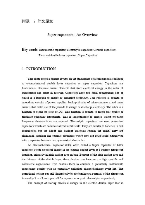
附录一:外文原文Super capacitors - An OverviewKey words: Electrostatic capacitor; Electrolytic capacitor; Ceramic capacitor;Electrical double layer capacitor; Super Capacitor1.INTRODUCTIONThis paper offers a concise review on the renaissance of a conventional capacitor toelectrochemical double layer capacitor or super capacitor. Capacitors are fundamental electrical circuitelements that store electrical energy in the order of microfarads and assist in filtering. Capacitors havetwo main applications; one of which is a function to charge or discharge electricity. This function isapplied to smoothing circuits of power supplies, backup circuits of microcomputers, and timer circuitsthat make use of the periods to charge or discharge electricity. The other is a function to block the flowof DC. This function is applied to filters that extract or eliminate particular frequencies. This isindispensable to circuits where excellent frequency characteristics are required. Electrolytic capacitorsare next generation capacitors which are commercialized in full scale. They are similar to batteries in cell construction but the anode and cathode materials remain the same. They are aluminum, tantalum and ceramic capacitors where they use solid/liquid electrolytes with a separator between two symmetrical electro des.An electrochemical capacitor (EC), often called a Super capacitor or Ultra capacitor, stores electrical charge in the electric double layer at a surface-electrolyte interface, primarily in high-surface-area carbon. Because of the high surface area and the thinness of the double layer, these devices can have very a high specific and volumetric capacitance. This enables them to combine a previously unattainable capacitance density with an essentially unlimited charge/discharge cycle life. The operational voltage per cell ,limited only by the breakdown potential of the electrolyte, is usually<1 or <3 volts per cell for aqueous or organic electrolytes respectively.The concept of storing electrical energy in the electric double layer that isformed at the interface between an electrolyte and a solid has been known since the late 1800s. The first electrical device using double-layer charge storage was reported in 1957 by H.I. Becker of General Electric (U.S. Patent 2,800,616).Unfortunately, Becker’s device was imp ractical in that, similarly to a flooded battery, both electrodes needed to be immersed in a container of electrolyte, and the device was never comercialised.Becker did, however, appreciate the large capacitance values subsequently achieved by Robert A. Rightmire, a chemist at the Standard Oil Company of Ohio (SOHIO), to whom can be attributed the invention of the device in the format now commonly used. His patent (U.S. 3,288,641), filed in 1962 and awarded in late November 1966, and a follow-on patent (U.S. Patent 3,536,963) by fellow SOHIO researcher Donald L. Boos in 1970, form the basis for the many hundreds of subsequent patents and journal articles covering all aspects of EC technology.This technology has grown into an industrywith sales worth severalhundred million dollars per year. It is an in dustry that is poised today for rapid growth in the near term with the expansion of power quality needs and emerging transportation applications.Following the commercial introduction of NEC’s Super Capacitor in 1978, under licence from SOHIO, EC have evolved through several generations of designs. Initially they were used as back-up power devices for v is for cells ranging in size from small millifarad size devices with exceptional pulse power performance up to devices rated at hundreds of thousands of farads, with systems in some applications operating at up to 1,500 volts. The technology is seeing increasingly broad use, replacing batteriesolatile clock chips and complementary metal-oxide-semiconductor (CMOS) computer memories. But many other applications have emerged over the past 30 years, including portable wireless communication, enhanced power quality for distributed power generation systems, industrial actuator power sources, and high-efficiency energy storage for electric vehicles(EVs) and hybrid electric vehicles (HEVs).Overall, the unique attributes of ECs often complement the weaknesses of other power sources like batteries and fuel cells.Early ECs were generally rated at a few volts and had capacitance values measured from fractions of farads up to several farads. The trend today in some cases and in others complementing their performance.The third generation evolution is the electric double layer capacitor, where the electrical charge stored at a metal/electrolyte interface is exploited to construct astorage device. The interface can store electrical charge in the order of 610Farad. The main component in the electrode construction is activated carbon. Though this concept was initialized and industrialized some 40 years ago, there was a stagnancy in research until recent times; the need for this revival of interest arises due to the increasing demands for electrical energy storage in certain current applications like digital electronic devices, implantable medical devices and stop/start operation in vehicle traction which need very short high power pulses that could be fulfilled by electric double layer capacitors. They are complementary to batteries as they deliver high power density and low energy density. They also have longer cycle life than batteries and possess higher energy density as compared to conventional capacitors. This has led to new concepts of the so-called hybrid charge storage devices in which electrochemical capacitor is interfaced with a fuel cell or a battery. These capacitors using carbon as the main electrode material for both anode and cathode with organic and aqueous electrolytes are commercialized and used in day to-day applications. Fig.1 presents the three types of capacitors depicting the basic differences in their design and construction.Figure 1.Schematic presentation of electrostatic capacitor, electrolytic capacitor and electrical double layer capacitor.EDLCs, however suffer from low energy density. To rectify these problems, recently researchers try to incorporate transition metal oxides along with carbon in the electrode materials. When the electrode materials consist of transition metal oxides, then the electrosorption or redox processes enhance the value of specific capacitance ca. 10 -100 times depending on the nature of oxides. In such a situation, the EDLC is called as super capacitor or pseudo capacitor . This is the fourth generation capacitor. Performance of a super capacitor combines simultaneously two kinds of energy storage, i.e. non-faradic charge as in EDLC capacitors and faradaic charge similar toprocesses proceeding in batteries. The market for EC devices used for memory protection in electronic circuitry is about $150-200 million annually. New potential applications for ECs include the portable electronic device market, the power quality market, due particularly to distributed generation and low-emission hybrid cars, buses and trucks. There are some published reviews on capacitors and super capacitors . In the present overview, the evolution of electrochemical double layer capacitors starting from simple electrostatic capacitors is summarized.2. EXPERIMENTAL PARTThe invention of Leiden jar in 1745 started the capacitor technology; since then, there has been tremendous progress in this field. In the beginning, capacitors are used primarily in electrical and electronic products, but today they are used in fields ranging from industrial application to automobiles, aircraft and space, medicine, computers, games and power supply circuits. Capacitors are made from two metallic electrodes (mainly Si) placed in mutual opposition with an insulating material (dielectric) between the electrodes for accumulating an electrical charge. The basic equation relating to the capacitors is:C = εS/d (1)where C(μF) is the electrostatic capacity, the dielectric constant of the dielectric, S (cm2) the surface area of the electrode and d (cm) the thickness of the dielectric. The charge accumulating principle can be described as follows: when a battery is connected to the capacitor, flow of current induces the flow of electrons so that electrons are attracted to the positive terminal of the battery and so they flow towards the power source. As a result, an electron deficiency develops at the positive side, which becomes positively charged and an electron surplus develops at the negative side, which becomes negatively charged. This electron flow continues until the potential difference between the two electrodes becomes equal to the battery voltage. Thus the capacitor gets charged. Once the battery is removed, the electrons flow from the negative side to the side with an electron deficiency; this process leads to discharging. The conventional capacitors yield capacitance in the range of 0.1 to 1 μF with a voltage range of 50 to 400 V. Various materials such as paper (ε, 1.2-2.6), paraffin (ε 1.9-2.4), polyethylene (2.2-2.4), polystyrene (ε, 2.5-2.7), ebonite (ε, 2-3.5), polyethylene tetraphtharate (ε,3.1-3.2), water (ε, 80) sulfur(ε, 2-4.2), steatite porcelain (ε, 6-7), Al porcelain (ε, 8-10), mica(ε, 5-7)and insulated mineral oil (ε, 2.2-2.4) are used as dielectrics in capacitors.The capacitance output of these silicon based capacitors is limited and has to cope with low surface-to volume ratios of these electrodes. To increase the capacitance, as per eq., one has to increase to ∂or S and decrease; however the ∂value is largely determined by the working voltage and cannot be tampered. When aiming at high capacitance densities, it is necessary to combine the mutual benefits achieved with a high permittivity insulator material and an increased effective surface area. With Si as the substrate material, electrochemical etching produces effective surface area. The surface area of this material gets enlarged by two orders of magnitude compared to unetched surface. Electrochemically formed macroporous Si has been used for the preparation of high aspect ratio capacitors with layered SiO2/Si3N4/SiO2 insulators. Research work on the modification of conventional capacitors to increase the specific capacitance is also in progress. Approximately 30 times higher capacitance densities are reported recently for Si/Al2O3/ZnO: Al capacitor where Si is electrochemically etched porous one. Another way identified to increase the surface area of the electrodes is to form anodically formed oxides (Al, Ta); however, ceramic capacitors are based on the high dielectric constant rather than the electrode area.3. ELECTROLYTIC CAPACITORSThe next generation capacitors are the electrolytic capacitors; they are of Ta, Al and ceramic electrolytic capacitors. Electrolytic capacitors use an electrolyte as conductor between the dielectrics and an electrode. A typical aluminum electrolytic capacitor includes an anode foil and a cathode foil processed by surface enlargement and or formation treatments. Usually, the dielectric film is fabricated by anodizing high purity Al foil for high voltage applications in boric acid solutions. The thickness of the dielectric film is related to the working voltage of the aluminum electrolytic capacitor. After cutting to a specific size according to the design specification, a laminate made up of an anode foil, a cathode foil which is opposed to the dielectric film of the anode foil and a separator interposed between the anode and cathode foils, is wound to provide an element. The wound element does not have any electricalcharacteristics of electrolytic capacitor yet until completely dipped in an electrolyte for driving and housed in a metallic sheathed package in cylindrical form with a closed-end equipping a releaser. Furthermore, a sealing material made of elastic rubber is inserted into an open-end section of the sheathed package and the open-end section of the sheathed package by drawing, whereby an aluminum electrolytic capacitor is constituted. Electrolytic aluminum capacitors are mainly used as power supplies for automobiles, aircraft, space vehicles, computers, monitors, motherboards of personal computers and other electronics.There are two types of tantalum capacitors commercially available in the market; wet electrolytic capacitors which use sulfuric acid as the electrolyte and solid electrolytic capacitors which use MnO2 as the solid electrolyte. Though the capacitances derived from both Ta and Al capacitors are the same, Ta capacitors are superior to Al capacitors in temperature and frequency characteristics. For analog signal systems, Al capacitors produce a current-spike noise which does not happen in Ta capacitors. In other words, Ta capacitors are preferred for circuits which need high stability characteristics. The total world wide production of Al electrolytic capacitors amounts to US$ 3.8 billion, 99% of which are of the wet type. Unlike Ta solid electrolytic capacitors, the solid electrolyte materials used are of organic origin; polypyrrole, a functional polymer and TCNQ (7,7, 8, 8- tetracyanoquniodimethane) an organic semiconductor. Next, MnO2 solid electrolyte material is formed on the surface of that dielectric layer and on top of that a layer of polypyrrole organic solid electrolyte material is formed by electrolytic synthesis. Following this, the positive and negative electrodes are mounted to complete the electronic component. However, the capacitances of these electrolytic capacitors are in the range 0.1 to 10F with a voltage profile of 25 to 50 V.The history of development of electrolytic capacitors which were mass produced in the past as well as today is presented by S. Niwa and Y. Taketani . Many researchers try to improve the performance of these electrolytic capacitors by modifying the electrode or electrolyte. Generally, the increases in effective surface area (S) are achieved by electrolytic etching of aluminum substrate before anodization, but now it faces with the limit. It is also very difficult to decrease d because the d value is largely decided when the working voltages are decided. Increase in may be a possible routine to form composite dielectric layers by incorporating relatively large value compounds. Replacement of MnO2 by polypyrrole solid electrolyte was reported to reduce electrostatic resistance due to its higher conductivity; aromaticsulfonate ions were used as charge compensating dopant ions .A tantalum capacitor with Ta metal as anode, polypyrrole as cathode and Ta2O5 dielectric layer was also reported. In the Al solid electrolytic capacitors, polyaniline doped with inorganic and organic acids was also studied as counter electrode. In yet another work, Al solid electrolytic capacitor with etched Al foil as anode, polyaniline / polypyrrrole as cathode and Al2O3 as dielectric was developed. Ethylene carbonate based organic electrolytes and -butyrolactone based electrolytes have been tried as operating electrolytes in Al electrolytic capacitors. Masuda et al. have obtained high capacitance by electrochemically anodizing rapidly quenching Al-Ti alloy foil. Many researchers have tried the other combination of alloys such as Al-Zr, Al-Si, Al-Ti, Al-Nb and Al-Ta composite oxide films. Composite oxide films of Al2O3-(Ba0.5Sr0.5TiO3) and Al2O3- Bi4Ti3O12 on low-voltage etched aluminum foil were also studied. Nb-Ta-Al for Ta electrolytic capacitors was also tried as anode material .A ceramic capacitor is a capacitor constructed of alternating layers of metal and ceramic, with the ceramic material acting as the dielectric. Multilayer ceramic capacitors (MLCs) typically consist of ~100 alternate layers of electrode and dielectric ceramics sandwiched between two ceramic cover layers. They are fabricated by screen-printing of electrode layers on dielectric layers and co-sintering of the laminate. Conventionally, Ag-Pd is used as the electrode material and BaTiO3 is used as the dielectric ceramic. From 2000 onwards, the MLCs market has been growing in pace with the exponential development of communications. They are produced in the capacitance range of 10 F (normally the range of Ta and Al electrolytic capacitors); they are highly useful in high frequency applications. Historically, a ceramic capacitor is a two-terminal non-polar device. The classical ceramic capacitor is the disc capacitor. This device predates the transistor and was used extensively in vacuum-tube equipment (e.g radio receivers) from c. a. 1930 through the 1950s and in discrete transistor equipment from the 1950s through the 1980s. As of 2007, ceramic disc capacitors are in widespread use in electronic equipment, providing high capacity and small size at low price compared to the other types.The other ceramic materials that have been identified and used are CaZrO3, MgTiO3, SrTiO3 etc. A typical 10 F MLC is a chip of size (3.2 x 1.6 x 1.5 mm). Mn, Ca, Pd , Ag etc are some of the other internal electrodes used. Linear dielectrics and antiferroelectrics based o strontium titante have been developed for high voltage disk capacitors. These are applicable for MLCs with thinner layers because of their high coercive fields. One of the most critical material processing parameters is the degreeof homogeneous mixing of additive in the slurry. The binder distribution in the green ceramic sheet, the degree of surface roughness, fine size nickel powder, formation of green sheet, electrode deposition ad sheet stacking etc play a crucial role in the process technology. Any one of these facts if mishandled would result in the failure of the device. For instance, providing a roughess of 5 m thick green sheet to 0.5 m is mandatory so that a smooth contact surface with the inner nickel electrode can be established. This is a very important factor in avoiding the concentration of electric filed at asperities, where the charge emission from the electrode is accelerated, resulting in short failure. Conventional sheet/printing method has a technical limit of producing a thickness around 1 m dielectric; in order to decrease the thickness further, thin film technologies like CVD, sputtering, plasma-spray etc has to be used.The other types of capacitors are film capacitors which use thin polyester film and polypropylene film as dielectrics and meta-glazed capacitors which incorporate electrode plates made of film vacuum evaporated with metal such as Al. Films can be of polyester, polypropylene or polycarbonate make. Also capacitors are specified depending on the dielectric used such as polyester film capacitor, polypropylene capacitor, mica capacitor, metallized polyester film capacitor etc.4. DOUBLE LAYER CAPACITORSElectric/electrochemical double layer capacitor (EDLC) is a unique electrical storage device, which can store much more energy than conventional capacitors and offer much higher power densitythan batteries. EDLCs fill up the gap between the batteries and the conventional capacitor, allowing applications for various power and energy requirements i.e., back up power sources for electronic devices, load-leveling, engine start or acceleration for hybrid vehicles and electricity storage generated from solar or wind energy. EDLC works on the principle of double-layer capacitance at the electrode/electrolyte interface where electric charges are accumulated on the electrode surfaces and ions of opposite charge are arranged on the electrolyte side.Figure 2.Charge storage mechanism of an EDLC cell under idle and charged conditions.Fig. 2 shows the mechanism of charge storage in an EDLC cell and Fig. 3 shows the configuration of an typical EDLC cell. There are two main types of double layer capacitors as classified by the charge storage mechanism: (i) electrical double-layer capacitor; (ii) electrochemical double layer capacitor or super/pseudocapacitor. An EDLC stores energy in the double-layer at the electrode/electrolyte interface, whereas the supercapacitor sustains a Faradic reaction between the electrode and the electrolyte in a suitable potential window. Thus the electrode material used for the construction of the cell for the former is mainly carbon material while for the latter, the electrode material consist of either transition metal oxides or mixtures of carbon and metal oxides/polymers. The electrolytes can be either aqueous or non-aqueous depending on the mode of construction of EDLC cell.Figure 3.Typical configuration of an EDLC cellThere are two general directions of interest. One is the long term goal of the development of electrical propulsion for vehicles, and the other is the rapid growth of portable electronic devices that require power sources with maximum energy content and the lowest possible size and weight.5. CONCLUSIONSAccording to a market survey by Montana, super capacitors are becoming a promising solution for brake energy storage in rail vehicles. The expected technological development outside railway sector is also shown to be highly dynamic: diesel electric vehicles, catenary free operation of city light rail, starting system for diesel engines, hybrid-electric cars, industrial applications, elevators, pallet trucks etc. The time horizon expected for development is next 5 to 10 years. The main development goals will be,· long life time· increase of the rated voltage· improvements of the range of operating temperature· increase of the energy and power densitiesVery recently, hybrid car is introduced in the market but it is turned to be very expensive and out of common man’s reach. Shortage and cost of fossil fuels already instigated alternate technologies viable for traction purposes. In such a situation,EDLCs are also useful to store energy generated from non-conventional energy sources. A future possibility of service centers set up for EDLC supply similar to petrol (as on date) is not far as the main setbacks in technology development may take a decade for fruitful results.附录二:外文译文超级电容器-概述关键词:静电电容,电解电容器,陶瓷电容器,双电层 ,电容器,超级电容器1.引言本文为电化学双层电容器或超级电容器提供在一台常规电容器,简明的介绍新生的电化学双电层电容器或超级电容器。
- 1、下载文档前请自行甄别文档内容的完整性,平台不提供额外的编辑、内容补充、找答案等附加服务。
- 2、"仅部分预览"的文档,不可在线预览部分如存在完整性等问题,可反馈申请退款(可完整预览的文档不适用该条件!)。
- 3、如文档侵犯您的权益,请联系客服反馈,我们会尽快为您处理(人工客服工作时间:9:00-18:30)。
本科生毕业设计(论文)外文翻译毕业设计(论文)题目:悬架系统设计与分析外文题目:An Overview of Disarray in Active Suspension System 译文题目:主动悬架系统杂谈学生姓名: XXX专业:车辆工程1002班指导教师姓名:田国富评阅日期:主动悬架系统杂谈帕蒂尔,维杰河帕蒂尔,加尼甚助理教授,机械工程系,A.D.C.E.T,阿什达摘要:当设计一个悬挂系统时,它的双重目标是尽量减少传到乘客的垂直力量和最大限度地提高轮胎与道路接触以提高操控性和安全性。
乘客的舒适性与从车身传递的垂直力有关。
这个目标可以通过最小化车身的垂直加速度来实现。
过度的车轮行驶,将导致轮胎相对路面的非最佳姿态,从而导致差的操控性和附着力。
此外,为了保持良好的操控性,轮胎与路面的最佳接触必须保持在四个轮子上。
在传统的悬架系统中,这些特点是冲突的,不符合所有条件。
因此,在被动悬架系统的基础上,为了改善主动悬架系统,各种各样的研究工作正在进行中。
在本文中各种作品的概述已经完成。
考虑到季度汽车模型,本文试图给出关于以往的研究和他们的发现对被动和主动悬架系统的参数。
关键词:主动悬架系统,控制系统,动态,被动悬架,车辆。
1.引言汽车悬架系统的目的是在不同路况下,能保持良好的操控特性和改善乘坐品质。
不同的悬架,满足上述要求的程度不同。
虽然,可由设计者的聪明才智来改善,就平均而言,悬架的性能主要取决于悬架使用的类型。
按改进的性能可以以升序区分为:与被动,半主动和全主动悬架系统,输入的力通常由液压致动器提供。
为主动悬架系统设计的机电致动器的另一种方法将在电子控制和悬架系统之间提供直接接口。
目前,公认的主动悬架有两种形式,一种是制动器和钢板弹簧平行的高带宽主动悬架。
第二种是低带宽主动悬架,它的致动器带有一系列的钢板弹簧并且能够控制车身的运动,而簧下质量控制是通过被动阻尼器控制的。
汽车悬架的主动控制在传统悬架的基础上又提出了新的改进。
主动悬架,包括创建悬挂系统中力的液压致动器。
由液压致动器产生的力被用来控制簧上质量的运动,以及簧上和簧下质量之间的相对速度。
为了提高车辆的特色,以后将主要对主动悬架的高带宽型进行研究。
考虑到上述事实,本文试图提出一些关于主动悬架系统的理论,并把悬架的非线性、平顺性和汽车操纵性的参数考虑进去。
本文综述了各种工作。
在前人对被动和主动悬架研究和发现的基础上,并把悬架的非线性、平顺性和汽车操纵性等参数考虑进去,本文试着提出了一个观点。
图1 高带宽系统2.改进后的半主动悬架系统天钩控制Keum-Shik Hong 和 Hyun-Chul Sohn al 在2002年研究了半主动悬架的改进的天钩阻尼控制并且演示了最佳一个和两个自由度的车辆主动悬架结构结合之间的连接。
结果表明,与两个自由度的相比较,特殊的单自由度结构代表最佳的性能可达到的极限。
3.汽车悬架替代控制法C.Yue 等人[ 3 ]讨论汽车主动悬挂系统的替代控制法。
他们用二自由度四分之一汽车模型评估了该控制规律。
控制法被认为是全状态反馈的簧载质量、绝对速度和使用悬架动挠度测量LQG 调节器。
他们发现,所有三个部分提高了性能,但整体采用悬浮偏转LQG 调节器提供最好的妥协,在乘坐舒适性、悬架动行程和轮胎力的变化之间。
作为比较基准的情况下,给出了无源系统车辆参数的加速度标准值。
在全状态反馈控制规律下,线性最优控制理论已被用于设计。
他们发现了一些有趣的特性。
结果表明,一个设计,强调舒适度传递函数。
主动悬架大大提高了1赫兹区域而不变的点(10.6Hz )消除了在轮胎跳跃方式上的任何作用。
他们还发现,有源系统的高频性能比被动系统更糟糕。
他们还发现,轮胎变形量的传递函数仅仅车身弹簧 阻尼器 控制器车轮轮胎在1Hz区域进行了改进。
绝对速度反馈提供相同的性能,也消除了高频刺耳的问题。
最佳的整体设计是以最简单、最廉价的变量来衡量LQG补偿器实现的。
加速度频率图2无源加速度加速度频率图3无源加速度在一个控制的意义上,使用致动器力的控制系统和悬架动挠度的测量是可控的和可观察到的,因此,我们可以设计为行驶品质或车辆行驶性能。
结果表明,行驶品质设计捕获了全状态设计的所有好的特点,消除或减少一些不好的特点。
4.主动悬架的非线性自适应控制Andrew Alleyne 等人[ 4 ]研究了以前开发的非线性滑动控制法,并应用于电液悬挂系统。
在最早期的研究中,悬架的最优控制法没有考虑执行器的动态。
听说他们在一个四分之一汽车主动悬架模型中,考虑了电液执行器的非线性动力学,并用这些动力学制定一个非线性控制法。
在本文中,基于Lyapunov 稳定性分析模型的标准方法被引入,为了减少误差。
用该分析模型仿真所显示的性能与实验结果如图4,为了提高汽车的乘坐质量对所使用过的是实验结果进行了调查。
图4一季度汽车模型和状态方程图5天钩簧上质量加速度(模拟)由于行驶品质与在车厢中感觉到的加速度有关,所以我们的任务是降低加速度,同时保持悬架系统的约束。
实现这一目标常采用的方法是“天钩阻尼”。
控制器的性能被定义为主动元件能够跟踪一个给定的“天钩”的力,这是由系统的状态确定的。
在各种非线性控制器下,主动系统的性能除了应相互比较外,还应簧上质量簧下质量和一个被动系统比较。
致动器,力产生元件是一个传统的四通阀液压执行器。
四通阀是由一个直流输入挡板阀控制的。
挡板阀使用的输入电流和液压辅助控制阀门的阀芯运动。
伺服阀的运动是第三级,包括挡板和阀芯阀。
在模拟的改进的自适应方案中,使用的参数并不限于以慢时变为标准的自适应方案;然而,他们被限制在恒定或缓慢时变的状态空间的区域内。
图5显示了天勾簧上质量的模拟加速度。
图6显示系统的实验结果,是在双表面滑动控制器的自适应控制下开发的。
图6 簧上质量加速度(实验)5. 线控电动液压驱动主动悬架的反推方法Claude Kaddissi等人[ 5 ]研究了基于反推方法的电液主动悬架控制。
由于液压元件的使用,使得主动悬架模型是高度非线性和非差异性,特别是伺服阀。
因此,强大的控制策略是必要的,而在反步这里使用的是强大的非线性逼近,它能够压倒所有这些事实。
这里的电液执行器是用来确保乘客的舒适度。
对于任何类型的悬架,其主要目的是减少车架的垂直运动,由于道路的缺陷。
这个结果意味着减少传递到乘客身上的力。
电液执行器通常被选择用于此目的,在悬架控制中。
听说,通过电液主动悬架线控的驱动器正在被研究,通过使用回步的方法。
这项工作的重点是,考虑到所有系统的非线性,包括一个由致动器室体积和零动态的稳定性的变化引起的。
图8所示的是一季度汽车模型的电液主动悬架。
悬架是由液压系统和构成经典被动悬架的弹簧-阻尼器系统所组成。
关于汽车动力学,用轮胎弹簧模拟平行弹簧和阻尼器。
听说主要目的是确保一个稳定的零动态。
关于液压系统,电机带动液压泵以恒定的速度运转。
然后,泵输出油流从油箱流到剩下的组件。
通常,泵的排出压力取决于负载(汽车和乘客的重量);但是,在任何情况下,它是稳定的,由于蓄能器和减压阀的存在。
事实上,蓄能器作为一个额外的压力源是必要的。
另一方面,安全阀补偿压力的增加,因为大的负载,通过返回的附加量流向油箱。
液压执行机构支撑悬架;决定悬架位移的运动和速度是解决来自油流量和压力来自伺服阀。
控制法,是通过以电信号设计的反推控制器产生的。
它驱动伺服阀阀芯依靠道路扰动来校正正确位置。
这反过来又决定了执行器的行动使汽车车身的垂直运动为零,这给出了一个对这一控制策略的线控驱动方面。
伺服阀反馈控制油缸路面干扰图8 四分之一汽车电液主动悬架图5显示了一个典型的被动悬架系统相同的数据。
图6显示了,使用反推非线性电液控制的主动悬架车身的垂直运动和传递到乘客身上的力。
在本文中,他们提出了一个非线性、线驱动、电动液压主动悬架的控制策略。
该控制律基于非线性反推。
从图6可以看出,所设计的控制器成功地稳定了车身的垂直运动和传递到乘客身上的力。
液压作动器是线性的,这增加了系统的非线性,由于油体积与活塞位置的变化。
这种不连续性产生的数学和数值的问题导致阀芯不得不从正切换到负的位置,反之亦然。
在数学模型中,我们引入了一个轮胎模型的阻尼系数;这确保了一个稳定的零动态能独立地控制变量的选择。
该结果和那些经典的被动悬架和PID控制器进行了比较。
Claude Kaddissi等人研究了使用间接自适应反步电液系统的实时位置控制,液压参数易发生的变化,它是采用一种自适应控制策略,以使更新控制器参数的变化是有用的。
用于此目的的自适应控制是有用的。
当处理电液系统时,第一个数学模型的正确性和控制策略的有效性被认为是重要的因素。
在本文中,液压参数的动态性被考虑到,并给出了在现有的系统中的一些改进。
对于控制问题,采用的是最有效的间接自适应控制系统。
本文提出了一种电液伺服系统的位置控制,它具有强大的反推策略的优点,同时考虑了系统参数的变化。
本文主要关注的是识别系统参数和操作系统条件的变化。
它的好处是,它保证了系统参数收敛到真实的物理参数值,同时保证系统的稳定性。
电动液压工作台是用于试验目的的一个间接自适应反推控制器。
和采用实时反推控制器得到的结果相比,电动液压元件的变化取决于负载的温度和压力的变化。
在参数变化期间,还发现参数变化后的自适应控制器能够有轻微的瞬态行为,并跟踪期望的参考信号。
本文证明间接采用的控制器是液压控制系统的理想选择,它导致了系统参数的实际值,它允许一个良好的监测系统。
6. 结论本文介绍了在汽车主动悬架控制系统的设计中,有关研究的最新进展。
以下结论可以从主动悬架系统的文献综述得出。
1. 电液执行器可以有效地用于汽车主动悬架。
2. 反推是汽车悬架控制的强大的战略,因为它控制的液压元件的非线性,特别是伺服阀的非线性。
3. 反推方法的主要目的是控制垂直运动,因此它提高了旅客的舒适性在其他的方法上。
4. 间接自适应控制器是液压控制系统的理想选择,因为它会导致系统参数的实际物理值,它允许一个良好的监测系统。
参考文献[1] D.H.Rovat, “Optimal Active Suspension for Quarter Car Vehicle Models”Automates, V ol.26.No.5.pp.860.1990.[2] Keum-Shik Hong, Hyun-Chul Sohn, J.Karl Hedrick “Modified Skyhook Controlof Semi-Active Suspensions: A New Model, Gain Scheduling, and Hardware-in-the-Loop Tuning”Journal of Dynamic Systems,Measurement, and Control, V ol 124, No.159-167[3] C. Yue, T. Butsuen,and J. K.Hedrick, “Alternative Control Laws for AutomotiveSuspensions” Automates,V ol. 26.No. 5.pp. 860.1990.[4] AndrewAlleyne, J. KarlHedrick, “Non Linear Adoptive Control of ActiveSuspensions,”IEEE Transactions on Control Systems Technology, V ol.3.No.1.March 1995.[5] Claude Kaddissi et al, “Drive by Wire Control of an Electro-Hydraulic ActiveSuspension a Backstepping Approach”. Proceedings of the 2005 IE Contron Applications Toronto, Canada, August 28-31, 2005.英文翻译指导教师评阅意见指导教师签字:年月日。