HZ-892A一体化振动变送器
E H仪器仪表价格选型报价
E+H 流量计 (工控仪表)50P2H-EC0A1AA0AAAA品牌:E+H 品名:流量计描述:Promag 50/53W 电磁流量测量,给排水领域的最佳流量测量工具货期待查咨询在线客服GkCity价:¥42,919.18E+H 分析仪 (分析仪表) CPA250-A00品牌:E+H 品名:分析仪描述:flowFit W CPA 250 pH/氧化还原测量,流通式支架货期待查咨询在线客服GkCity价:¥5,109.43E+H 分析仪 (分析仪表) CLM253-ID0005品牌:E+H 品名:分析仪描述:liquisys M CLM223/253变送器采用模块化设计,应用广泛。
基本型变送其提供简单的测量和报警功能,扩展功能软件和硬件模块化后可以应用于特殊的场合,如果需要,可使用扩展模块。
货期待查咨询在线客服GkCity价:¥13,275.36E+H 流量计 (工控仪表) 53P15-EA1B1AAOAGAA品牌:E+H 品名:流量计描述:公称直径DN 25...2000 硬橡胶或聚氨酯衬里装配长度符合DVGW及ISO 测量精度高,有利于提高过程控制质量: - Promag50:±0.5%(可选:± 0.2%) - Promag 53:±0.2% 服务及维护简单精确现场标定无需拆下传感器: - 设备维护最优化 - 可与QA系统集成坚实的现场安装外壳IP 67 IP 67墙装外壳可对远程型直接安装 Promag 53带光敏键:外部操作 - 无需打开外壳用于现场直接通讯的快速设定菜单可以和多种过程控制系统的通信接口相连: - 标准HATR接口 - Promag 50:PROFIBUS-PA - Promag53:PROFIBUS-PA/-DP基金会现场总线饮用水行业认证: KTW,NSF,WRC等货期待查咨询在线客服GkCity价:¥35,079.64E+H 分析仪 (分析仪表) CPM253-PR0010品牌:E+H 品名:分析仪描述:liquisys M CPM223/253变送器采用模块化设计,应用广泛。
和利时LM可编程控制器硬件手册

如何使用手册 如果您需要了解PLC的硬件组成,请仔细阅读第1、2章。 如果您需要对本公司产品的技术规格、端子定义与接线示意图等内容有所了解,请参阅第2、 3章。 如果您需要了解安装、拆卸等原则,请仔细阅读第4章。附录A为LM系列小型PLC产品订货 清单。附录B为LM系列小型PLC通用技术规范。
CPU模块本身集成了一定数量的本机I/O点,其中一部分I/O点同时具有高速计数、高速输出 等功能。随着系统需求的扩大,将需要更多的I/O点数,通提出了一些PLC现场应用原则。
读者 《LM小型可编程控制器硬件手册》适用于有一定PLC背景知识的工程师、安装人员、技术 人员及电气人员。
HollySys Group
版权申明
本手册内容,包括文字、图表、标志、标识、商标、产品型号、软件程序、版面设计等, 均受《中华人民共和国著作权法》、《中华人民共和国商标法》、《中华人民共和国专利法》 及与之适用的国际公约中有关著作权、商标权、专利权或其他财产所有权法律的保护,为北京 和利时系统工程股份有限公司专属所有或持有。
内容 《LM小型可编程控制器硬件手册》是和利时公司对LM系列PLC产品从特性、技术规格等方 面进行详细介绍的技术手册,包含了LM小型PLC所有的硬件信息。
第1章从硬件体系结构、编程软件、快速应用等各个方面对LM小型PLC作了概述性介绍。
第2、3章主要针对CPU模块、扩展模块的技术规格、端子定义与接线示意图及等效电路进行 了详细阐述。
第 2 章 CPU 模块 ............................................................................................... 10
Keysight M8920A PXIe 无线电测试设备说明书
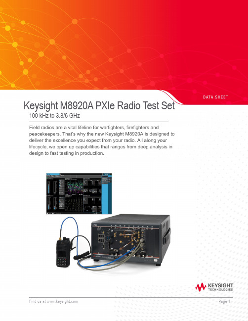
Keysight M8920A PXIe Radio Test Set 100 kHz to 3.8/6 GHzField radios are a vital lifeline for warfighters, firefighters andpeacekeepers. That’s why the new Keysight M8920A is designed to deliver the excellence you expect from your radio. All along your lifecycle, we open up capabilities that ranges from deep analysis in design to fast testing in production.Table of ContentsAccelerate MilCom and public safety radio manufacturing (3)Applications (3)Technical Specifications (4)Definitions and conditions (4)RF Analyzer Technical Specifications and Characteristics (5)RF Analyzer Technical Specifications and Characteristics (Continued) (6)RF Generator Technical Specifications and Characteristics (7)RF Generator Technical Specifications and Characteristics (Continued) (8)Audio Module Technical Specifications and Characteristics (8)Audio Module RX Audio Filters (9)Radio Test Application Specifications (9)N9093EM0E basic analog demodulation measurement application key specifications (9)N9093EM1E basic digital demodulation measurement application key specifications (9)Connectivity Test Application Specifications (10)WLAN 802.11ac (10)LTE-FDD/TDD (10)Bluetooth (10)Front Panel M9470A RF Interface Module Connections (10)General Specifications (11)Related Literature (12)Additional Information (12)Accelerate MilCom and public safety radio manufacturingDigital 2-way radios being developed for MilCom and the public safety radio market bring new testing challenges and hurdles to overcome for manufacturers and depot testing. Radio technologies are requiring wider bandwidths, higher frequencies, and multiple radio format capabilities.Product descriptionKeysight’s M8920A PXIe Radio Test Set supports many formats by combining PXI hardware with application-specific software in a single flexible and scalable chassis, providing broad multi-format coverage for next-generation radio testing.With Keysight’s new Radio Test Measurement Application (N9093), you can access and control multiple instruments on one screen while viewing a variety of critical measurements at the same time. Keysight can help deliver the operational excellence you expect from your radio.Applications−Cover all necessary analog AM and FM modulation test requirements.−Test APCO P1/P2, TETRA1, DMR, dPMR, ARIB, and custom modulation formats.−Test commercial connectivity formats including WLAN, LTE, Bluetooth®, etc.−All measurements can be performed with one click of a button.−Test analog Avionics Radios, and your Avionics Databus with optional Databus modulesM8920A PXIe Radio Test SetTechnical SpecificationsDefinitions and conditionsSpecifications describe the warranted performance of calibrated instruments. Data represented in this document are specifications under the following conditions unless otherwise noted.−Specifications are valid from 40° to 65 °C for individual module temperature, as reported by the module, and 20° to 35 °C for environment temperature unless otherwise noted −Calibrated instrument has been stored for a minimum of 2 hours within the allowed operating range−If instrument has previously been stored at a temperature range inside the allowed storage range, but outside the allowed operating range, instrument must have been stored for a minimum of 2hours within the allowed operating range before turn-on−30-minute warm-up time−Calibration cycle maintained−The RF, IF, and Source Alignments have been run within the previous 7 days−An ALL Alignment has been run within the previous 8 hours−If the temperature has changed more than 5 °C from the previous ALL AlignmentTypical describes additional product performance information that is not covered by the product warranty. It is performance beyond specifications that 80% of the units exhibit with a 95% confidence level. This data, shown in italics, does not include measurement uncertainty, and is valid only at room temperature (approximately 25 °C) after alignment within the stated alignment time and temperature limits.Nominal values indicate expected performance or describe product performance that is useful in the application of the product but are not covered by the product warranty.Recommended best practices in use−Use slot blockers and EMC filler panels in empty module slots to ensure proper operating temperatures. Keysight chassis and slot blockers optimize module temperature performance and reliability of test.−Set chassis fan to high at environmental temperatures above 45 °C.RF Analyzer Technical Specifications and Characteristics1.Instantaneous b andwidth (1 d B b andwidth) a vailable a round a c enter frequency o ver w hich t he i nput s ignal c an b e d igitized f or further a nalysis o rprocessing in the time, frequency or modulation domain.2.Calibration a ccuracy d epends o n h ow a ccurately t he f requency s tandard w as a djusted t o 10 M Hz. I f t he a djustment p rocedure i s f ollowed, t he c alibration accuracyis given by the specification. Achievable Initial Calibration Accuracy.3.The 3-dB cutoff frequency can be selected for the User-defined audio filters.RF Analyzer Technical Specifications and Characteristics (Continued)1.T/R port high power attenuation OFF2.Except at 100 MHz, 5 GHz, and 5.5 GHzRF Generator Technical Specifications and Characteristics1.Calibration a ccuracy d epends o n h ow a ccurately t he f requency s tandard w as a djusted t o 10 M Hz. I f t he a djustment p rocedure i s f ollowed, t he c alibrationa ccuracy is given by the specification. Achievable Initial Calibration Accuracy.2. Specifications apply when input port is set to Antenna InRF Generator Technical Specifications and Characteristics (Continued)Audio Module Technical Specifications and CharacteristicsAudio Module RX Audio FiltersRadio Test Application SpecificationsN9093EM0E basic analog demodulation measurement application key specificationsN9093EM1E basic digital demodulation measurement application key specifications1. The 3 dB cutoff frequency can be selected for the User-defined audio filters.Connectivity Test Application SpecificationsWLAN 802.11acLTE-FDD/TDDBluetoothFront Panel M9470A RF Interface Module ConnectionsGeneral SpecificationsFind us at Page 11PPFind us at Page 12Learn more at: For more information on Keysight Technologies’ products, applications or services , please contact your local Keysight office. The complete list is available at: /find/contactusThis information is subject to change without notice. © Keysight Technologies, 2018, Published in USA, Month July 11, 2019, 5992-2802ENRelated LiteratureFor more detailed product and specification information refer to the following literature and web pages: Publication titlePublication number M8920A PXIe Radio Test Set Technical Overview 5992-2821EN M8920A PXIe Radio Test Set Configuration Guide 5992-2800EN M8920A PXIe Radio Test Set Getting Started Guide M8920-90001 M9470A PXIe 50W Interface Module Data Sheet 5992-3140EN M9421A VXT PXIe Vector Transceiver Data Sheet 5992-1646EN M9260A PXIe Audio Analyzer Data Sheet 5992-1918EN PXIe Chassis Spec GuideM9019-90015 PC Tested Configurations with PXIe Chassis Technical Overview 5990-7632EN M9037A PXIe Embedded Controller Spec Guide M9037-90015 Interface Modules and Adapters for PXIe Systems5992-0377EN M924XA InfiniiVision PXIe Modular Oscilloscopes Data Sheet 5992-2003EN 6.5 Digit PXI Digital Multimeter Data Sheet 5992-2757EN PXIe Vector Network Analyzer Configuration Guide 5991-4885EN PXI Avionics Bus Interface Cards Configuration Guide 5992-2448EN 89600 VSA Software Configuration Guide5990-6386ENAdditional InformationProduct webpages:/find/M8920A /find/N9093 /find/PXIX-Series measurement applications: /find/X-Series_AppsSignal Studio Software:/find/signalstudio89600 VSA Software:/find/89600Bluetooth and the Bluetooth logos are trademarks owned byBluetooth SIG, Inc., U.S.A. and licensed to Keysight Technologies, Inc。
Agilent8922M

Agilent8922MGSM\CDMA手机综合测试仪产品型号: 综合测试仪Agilent8922M产品说明与介绍8922GSM测试装置8922GSM测试装置可以理想地用于R&D、高层维护服务和生产制造方面。
易于使用、丰富而灵活的功能特性使它成为实验台工作选择的仪器。
8922的速度、准确度和重复度使它能够理想地用于来货输入检验和大量生产方面。
8922包括一个GSM基站仿真器及所有信令和测量的能力,能够全面地测试移动台而无需任何附加设备。
GSM无线电测试解决方案8922是一套完整的测试GSM无线台射频部分的测量仪器。
除了频率易变的0.3GMSK 射频发生器外,RF分析仪还有灵活的本地振荡器、相关数据解调节器、脉冲解调器、调频解调器、用于分析相位和频率误差的综合方法分析仪、合成频谱分析仪和脉冲功率计。
8922增加了一个用于完成GSM接收机测量、信道CODEC和呼叫控制协议的误码率测试仪(BERT),以便在进行测量的同时建立电话呼叫并保持链路。
通过用于移动台功能测试的声频CODEC简化了回波模式,并且利用电气人机接口(EMMI)来控制移动台和支持数字音频接口(DAI)。
8922中的快速存储器易于升级。
GSM 数据和HSCSD 测试解决方案8922支持测试GSM单时隙数据和高速电路交换数(HSCSD)移动台的能力。
用在R&D、生产和维修方面,选件K09、K17和K18能够测试单时隙、2x1、2x2、9.6Kb/s和14.4Kb/s 移动数据装置。
完整的成套工具除了完整配套的GSM测量之外,Agilent 8922还包括对于模块测试、排除故障以及调谐作业等有效的通用工具。
这些工具包括一台数字示波器、CW RF合成器、频谱分析仪、CW RF频率计数器、CW和峰值RF功率计、交流电压表、直流电压表、1kHz失真/SINAD(信号对噪声和失真比)测试仪、音频频率计和合成声源。
这些功能的组合使8922对于GSM无线设备的制造和修理都是极为有效的工具。
Fluke 8920A、8921A和8922A多功能电压计说明书

FLUKE 8922A8920A, 8921A & 8922AAutorangingFluke's autoranging feature allows you to carry out your testing without having to change ranges manually. A range can be placed on HOLD or manually stepped up to a higher range. On HOLD, the meter will remain in a given range regardless of changes in input levels. On STEP UP, the meter will increase ranges step-by-step until the switch is released. Peaking/Dipping MeterIn addition to an accurate digital display, all Fluke Voltmeters in the 8920-Series feature an analog meter for peak and null voltage adjustments. The meter indicates O to 100 percent full scale in each range.Linear Analog OutputModels 8920A and 8922A are equipped with a rear panel output for driving X-Y or st d p chart recorders, delivering voltages proportional to the display count. A 2-volt level equals 2000 counts, a 1-volt level equals 1000 counts, etc. This feature is not available on Model 8921A. AccuracyFluke Digital Voltmeters avoid the possibilities for error so common in analog meters. The digital displays eliminate the likelihood of misreading the meter due to viewing angle problems of parallax common with analog meters. Also, the accuracy of 8920-Series Voltmeters is specified as a percent of reading rather than as percent of full scale.Percent of reading accuracy does not degrade for measurements at the low end of a scale. Front panel switching offers a choice of readings in dB or volts.Technical SpecificationsThe a ccuracy s pecifications b elow apply from 9% to 100% of full scale and from 18°C to 28°C for 90 days. For six-month specifications multiply figures by 1.5.AC Accuracy: ± % of voltage reading or ±dB (8920A/8921 A)Range 2Hz 10 H z 20Hz 50Hz 10 kHz 700V200V1%or 0.5%or 20V 0.15dB 0.1 dB 2V Not200mV Speci-5%orlied 0.5dB 2%or 1%or 20 m V 0.25 d B 0.15dB3%or 2%or 2mV0.35dB 0.25dBAC Accuracy: ± % of voltage reading or ±dB(8922A)Range 2Hz 10 H z 20Hz 50Hz 10 k HzFILTER IN I700V200V 1%or•0.15 d B 1%or 0.5%or20V 0.15 d B 0.1 d B2V 5%or200 mV 3%or• 0.5dB0.35dB2%or•0.25dB 2%or 1%or20 mV 0.25 d B 0.15 d B5%or0.5dB5%or• 5%or 3%or 2%or I2 mv0.5 d B .. 0.5dB 0.35 d B 0.25dB• Valid when AC + DC DAMPING is selected andinput has no de components.••Below 2 mV add number of digits (N) to ±5% voltage readings, where N = 5 + mV input. Or, for dBreadings. add N to ±0.5 dB, where N = 0.5 + (mVinput)2AC+DC Accuracy: Add to AC accuracy specifications (above) ±10 digits or ±0.5 dB above 2mV, or ±100 digits or ±5.0 dB below 2 mV. Forde only, add above digits to 50 Hz to 10 kHzspecificationsFunctions: True RMS measurements only. ACor AC+ DC (8920A and 8921 A); AC or AC+ DCwith damping (8922A)Maximum Input: 700V rms or 1 O OOV peak, not toexceed a volt-hertz product of 1 x 10⁸ on anyrangeMaximum Common Mode Voltage8920A and 8922A: 400 mV rms or 600 mVpeak8921A: 500V rms or 700V peakAC Common Mode Rejection: �60 dB at 50 and60 Hz with 1000 unbalanceDC Common Mode Rejection: �100 dB, 1000unbalanceCrest Factor: 7 at full scale, increasing downscale by 7 times the voltage range divided by thevoltage input. Degrades below 10 Hz, annunciated when capability exceeded (8922A only)Input Impedance: 10 MO shunted by <30 pF200kHz 1 MHz 2MHz 10 M Hz 20MHzNot Specified0.7%or0.15 d B3% o r0.35 d B 5%or0.5dB2%or0.25dB 4%or0.4dB I3%or0.35dB200kHz 1 MHz 2MHz 11 MHzFILTER OUTNot Specified0.7%or0.15 d B3%or0.35 d B2%or 5%or0.25 d B 0.5dB4% o r0.4 d BVoltage R11nges: 2 mV, 20 mV, 200 mV, 2V, 20V,200V, 700VRanging: Autoranging with HOLD to defeat a�to•ranging and STEP UP for manual ranging.Ranges up at 2000 counts and ranges down at180 countsDecibel Ranges: In the autorange mode, theinstrument appears as though it has a singlerange spanning 131 dBdBm Reference: Twelve user-selectable impedances are provided to reference a O dBm, 1mW level (500,750,930, 1100, 1240, 1350,1500, 3000, 6000, 9000, 10000, and 12000)(dBV = 10000)Relative dB Reference: A voltage input presentwhen this button is pushed is held as "O dB"reference point. Subsequent readings indicate±deviations from this pointVoltage Resolution: 0.05% of ranges (3½ digits)Decibel Resolution: O.Q1 dB (4½ digits)Typical-3 dB Points: 40 MHz on 20 mV thru 20Vranges and 4 MHz on 2 mV range (8920A/8921 A); 22 MHz on 2 mV to 20V ranges (8922A)Low Pass Filter: Approximately 200 kHz -3 dBpoint, on 8922A onlyReading Rate: 2.5/s or 1 /s with ac + de withdamping (8922A)Autorange Rate: <950 ms or <3.5s with ac + dewith damping (8922A)Response Time: (To rated accuracy) <1.6s or<7s with ac + de with damping (8922A)Readout: Panel-select able for volts or dB,auto•matic decimal point location: analog peaking/dipping meter. " V .. "V .. "dB,,LED Annunciators: Indicate m , ,"REL REF," and "2 MHz MAX" for 2 mV range(8920A and 8921A) and "UNCAL" when crestfactor limitation exceeded (8922A)Overrange: Flashes maximum reading for thatrangeUnderrange: Flashes decimalLinear Analog Output: (8920A and 8922A only)Linear output of 2000 mV de for a 2000-countreadout; ±1.0% relative to display; essentiallyoo output into a �10 kO load; non-isolated, withoutput common same as input common。
8921a使用手册

8921a使用手册对于编号8921a的使用手册,我会从多个角度来回答你的问题。
首先,我会介绍这个产品的基本信息,包括其功能和用途。
其次,我会讨论产品的操作方法和注意事项。
最后,我会提供一些可能的故障排除方法和维护建议。
请注意,由于我无法直接获取特定产品的详细信息,以下内容仅供参考,具体以实际使用手册为准。
编号8921a的使用手册是一份重要的指南,它为用户提供了产品的详细信息和使用说明。
首先,让我们来看看这个产品的基本信息。
编号8921a可能是某种设备、机器或工具的型号,它可能具有特定的功能和用途。
在使用手册中,通常会包括产品的规格参数、功能特点、适用范围等内容,让用户了解产品的基本情况。
接下来,让我们来讨论产品的操作方法和注意事项。
使用手册通常会详细介绍产品的操作步骤、使用方法以及注意事项。
这些内容对于用户正确、安全地操作产品非常重要。
操作方法可能涉及到各种按钮、控制器或者界面操作,而注意事项则可能包括安全警示、使用环境要求、维护保养等方面的内容。
最后,让我们来提供一些可能的故障排除方法和维护建议。
在使用手册中,通常也会包括一些常见故障的排除方法,以及产品的维护保养建议。
这些内容可以帮助用户在产品出现故障时快速定位问题并进行处理,同时也可以延长产品的使用寿命。
综上所述,使用手册对于用户正确、安全地使用产品非常重要。
通过详细的介绍产品信息、操作方法、注意事项以及故障排除方法和维护建议,使用手册可以帮助用户更好地了解和使用产品。
希望我的回答能够帮助到你,如果你有任何其他问题,欢迎随时向我提问。
DSM8925 数字声级计使用手册说明书
DIGITAL SOUND METER WITH JUMBO DISPLAY USER’S MANUALDSM8925Please read this manual carefully and thoroughlybefore using this product.TABLE OF CONTENTS Introduction . . . . . . . . . . . . . . . . . . . . . .3 Key Features . . . . . . . . . . . . . . . . . . . . .4 What’s in the Box . . . . . . . . . . . . . . . . .5 Product Overview . . . . . . . . . . . . . .5 –7 Setup Instructions . . . . . . . . . . . . . . . . .8 Install Batteries . . . . . . . . . . . . . . . .8 Operating Instructions . . . . . . . . .8 –15 Making Basic Measurements . .8 –9 Autoranging vs.Manual Ranging . . . . . . . . . . .9 –11 Time and FrequencyWeighting Options . . . . . . . . .11 –12 Storing and RecallingMIN and MAX Readings . . . .12 –13 Operating inMAX HOLD mode . . . . . . . . . .13 –14 Disabling Auto Power Off . . . . . . .14 Calibrating the Meter . . . . . . . . . .15 Specifications . . . . . . . . . . . . . . . . . . .16 Maintenance Tips . . . . . . . . . . . . . . . .17 Warranty Information . . . . . . . . . .17 –18 Return for Repair Policy . . . . . . . . . . .182INTRODUCTIONThank you for purchasing General Tools & Instruments’ DSM8925 Digital Sound Meter with Jumbo Display. Please read this user’s manual carefully and thoroughly before using the instrument.The DSM8925 uses an integrated condenser microphone to measure the noise level of an environment or the loudness of a machine, typically in order to comply with health and/or safety rules. The meter has a range of 30 to 130 dB and an accuracy of ±2 dB. Real-time measurements are shown within a backlit liquid-crystal display window in two forms: as a three- or four-digit number, and as a line on an analog bar graph.Several features improve the meter’s versatility. Among them are two user-selectable operating modes: “A” or “C”frequency weighting, and fast or slow time response. Users also can override autoranging (the default mode) and manually select a fixed measurement range, improving the meter’s response time and measurement resolution. The meter can display the minimum and maximum sound levels measured during a recording session, as well as hold a maximum level on-screen until it is exceeded.3Physical features of the DSM8925 include an analog output jack for connecting to a data logger or chart recorder, a tripod mounting socket, and an adjustment screw for calibrating the meter to a standard 94 dB input.The DSM8925 includes a wind shield ball and is powered by four “AAA” batteries (also included).KEY FEATURES• Measures sound level of a machineor an environment• Jumbo LCD is easy to read• “A” or “C” frequency weighting• Fast or slow time weighting• Autoranging or manual ranging• Displays maximum and minimum readings • Max reading can be held until exceeded • Auto power off• Analog output for data logging• Calibrates to standard 94dB signal• Tripod mount socket on back• Includes wind shield ball• Powered by four “AAA” batteries4WHAT’S IN THE BOXThe DSM8925 comes fully assembled in a box along with a wind shield ball, four “AAA”batteries and this user’s manual.PRODUCT OVERVIEW Figure 1 shows all of the controls, indicators and connectors on the front and right side of the DSM8925. Familiarize yourself with their positions and functions before moving on to the setup procedure.1. The DSM8925’s controls, indicators and connectorsA.Wind shield ballB.MicrophoneC.Liquid-crystal displayD.Power on/off buttonE.A/C —Selects “A” or “C” frequencyweighting 5EF FRONTF.REC—Enters/exits Recording modeG.RNG—Selects autoranging or manualrangingH.F/S—Selects fast or slow time responseI.MAX HOLD buttonJ.Calibration adjustment screwK.Analog output jackFigure 2 shows all text and icons that could appear in the display window at various times.2. All possible display indications and their meaningsREC Meter is in Recording mode, trackingmaximum and minimum sound levelmeasurementsMAX Digital readout is highest levelrecorded since entering RecordingmodeMIN Digital readout is lowest levelrecorded since entering RecordingmodeMAX HOLD Meter is in Max Hold mode. Digitalreadout is highest level measuredsince entering this mode6FAST Meter is applying fast time weightingto inputsSLOW Meter is applying slow time weighting to inputsAUTO Meter is automatically choosingmeasurement range with bestresolutionMANU Meter is using user-selectedmeasurement rangeBA Reserved for future useSPL Abbreviation of sound pressure level(the parameter measured)Meter’s battery is very low on charge Array and should be replacedA Meter is applying “A” frequencyweighting to inputsC Meter is applying “C” frequencyweighting to inputsdB Sound level unit (accompaniesreading at its left)40Range Baseline (low end of currentmeasurement range, in dB). “40”indicates 40 to 70 dB range; otherpossible numbers in this displayposition are 60 (for 60 to 90 dBrange), 80 (for 80 to 110 dB range)and 100 (for 100 to 130 dB range)+0, +10,Labels of analog bar graph scale.+20, +30Indicate amplitude of input (in dB)relative to Range Baseline above leftend of graph7SETUP INSTRUCTIONS INSTALL FOUR BATTERIESThe meter’s battery compartment is accessible from the back of the unit. Use a Philips-head screwdriver to remove the one screw holding the cover in place. Then install the four included “AAA” batteries so their + and – ends match the images stenciled inside the compartment. Finally, replace the cover and secure it with the Philips-head screw. OPERATING INSTRUCTIONSMAKING BASIC MEASUREMENTSTo begin, press the button to power on the meter. The display will take a few seconds to stabilize and then begin reading out real-time sound level measurements.Note how the digital numbers and the readings from the analog bar graph track each other. At times, the two displays may seem slightly out of sync—and they are, because they refresh at different rates.Also note how the number above the left end of the bar graph—the Range Baseline—changes each time a much louder or softer sound is heard. Each change confirms that the meter is operating in Autoranging mode. To demonstrate that autoranging is on in a quiet environment, rub the windscreen with your hand (to simulate a loud noise) and watch the Range Baseline change to 100.8To measure the loudness of a sound source, point the microphone at it.The meter’s default settings are autoranging on (enabling measurements from 30 to 130 dB), fast time weighting and “A” frequency weighting. When the meter is powered on, AUTO will appear on the left side of the display, with FAST on the top line and A on the right side. Following are procedures for changing each of these settings to suit the application.AUTORANGING VS.MANUAL RANGINGThe DSM8925 has four measurement ranges: 40 to 70 dB, 60 to 90 dB, 80 to 110 dB, and 100 to 130 dB. When the meter is powered on, it automatically enters Autoranging mode. In this mode, it automatically switches to the range that displays the input with the finest resolution. For example, the meter could display a sound level of 65 dB using either the 40 to 70 dB or the 60 to 90 dB range. In autoranging mode, it would choose the lower of the two ranges (40 to 70 dB) because on this scale 65 dB has a better (finer) measurement resolution.If you already know the loudness range of the machine or environment you wish to measure, and that range is limited, consider exiting autoranging mode and operating the meter in only one of those four fixed ranges. The benefit of operating the meter in this mode—called Manual Ranging mode—is speed.9The meter can display its results more quickly because it does not have to first determine which range to use.To exit Autoranging Mode and enter Manual Ranging mode, briefly press the RNG button on the front panel. Note that when you press the button, the text MANU replaces AUTO on the left side of the display. Also note that the Range Baseline above the left end of the bar graph no longer changes in response to louder or softer sounds, as in did in Autoranging mode.When the RNG button is pressed, the meter randomly chooses one of the four ranges. Accordingly, the first Range Baseline number displayed could be 40, 60, 80 or 100. For the highest display resolution, the low end of the range you choose should be just below the quietest sound you expect to hear. For example, if your target normally produces sound levels between 85 and 105 dB, you should manually choose the 80 to 110 dB range.To manually select a specific measurement range, briefly press the RNG button as many times as necessary until its Range Baseline number appears above the left end of the analog bar graph. Each press of the RNG button advances the Range Baseline number by 20 dB; after 100, it returns to 40.Note that in Manual Ranging mode, whenever a sound level is outside the chosen range the 10digital display will show the letters LO or HI. If this happens often, consider switching back to Autoranging mode.To exit Manual Ranging mode and return to Autoranging Mode, press and hold the RNG button until the text AUTO replaces MANU on the left side of the display.TIME AND FREQUENCY WEIGHTING OPTIONSYou can choose Fast or Slow response time and “A” or “C” frequency weighting to suit different applications.By default, when the meter is powered on it begins operating with fast time weighting (a fast integration time constant) and “A”frequency weighting. Fast time weighting, with a response time of 200 milliseconds, simulates the response time of the human ear and is better for measuring the volume of singular events. Slow weighting, with a response time of 500 ms, is a better choice for measuring the average sound level that an ongoing process (such as machine vibration) produces over time.To switch the meter’s response time from fast to slow, press the F/S button. The word on the right side of top line of the display will change from FAST to SLOW. To return to fast time weighting, press the F/S button again. As mentioned earlier, when the DSM8925 is powered on it begins operating with “A”frequency weighting. The shape of the “A”11curve simulates the response of the human ear, and is therefore the better choice for measuring the sound level of an environment for the purpose of regulatory compliance, workplace design or noise-pollution control. By comparison, the “C” weighting curve is flatter, and is therefore better for measuring the sound level of a piece of machinery. In the U.S., most OSHA-mandated sound level measurements are made by instruments set for slow response and “A” frequency weighting.To switch from “A” frequency weighting to “C” weighting, press the A/C button. The letter at the right of the display will change from A to C. To switch back to “A” frequency weighting, press the A/C button again. STORING AND RECALLINGMIN AND MAX READINGSThe DSM8925 can also operate in “Recording” mode, for the purpose of tracking and displaying minimum and maximum sound level measurements.To enter Recording mode, press the REC button briefly. The text REC will appear at the upper left of the display.To display the minimum sound level measured since entering Recording mode, press the REC button briefly again. The text MIN will appear on the top line of the display and the digital display will indicate the lowest sound volume measured during this recording 12session. While the digital display is showing the minimum sound value, the meter continues to measure real-time sound level inputs and to display its results on the analog bar graph.To display the maximum sound level measured since entering Recording mode, press the REC button briefly one more time. The text MAX will replace MIN on the top line of the display and the digital display will indicate the highest sound volume measured during this recording session. While the digital display is showing the maximum sound value, the meter continues to measure real-time sound level inputs and to display its results on the analog bar graph.To repeat the process, press and hold the REC button briefly. This does not begin a new recording session. It simply extends the duration of the current session.To exit Recording mode, press and hold the REC button until the text REC disappears from the top line of the display.OPERATING IN MAX HOLD MODE You may want to use the meter’s digital display to show the loudest sound level measured up to a certain point in time. In this operating mode—called MAX HOLD mode—the digital display shows and holds the loudest sound level received since entering that mode. The analog bar graph continues to display measured input levels in real time.13However, the digital display is updated only when the meter detects a louder sound.To enter MAX HOLD mode, press the MAX HOLD button at the lower right of the front panel. To exit this mode, press the MAX HOLD button againDISABLING AUTO POWER OFFBy default, the meter powers off automatically after 20 minutes to avoid discharging the batteries. However, you can disable this feature if you would like to track sound levels over a longer period of time. For this purpose, you will also need to feed the meter’s analog output signal (available via a jack on the right side of the unit) into a chart recorder or data logger.To disable Auto Power Off, first power off the meter by pressing the button. Then power on the meter in a special way by pressing the button and pressing and holding the MAX HOLD button at the same time. This will cause the letter “n” to appear briefly on the digital display. Once “n” has appeared, you can release the MAX HOLD button.Once Auto Power Off has been disabled, the meter will no longer shut down automatically after 20 minutes. It will remain on until the button is pressed again to power off the instrument. Once the meter is powered off, Auto Power Off will automatically be re-enabled when the meter is powered on again. 14CALIBRATING THE METERThe DSM8925 must be calibrated beforeit can make accurate sound level measurements. To begin, obtain a standard acoustic calibrator with a 94 dB output, such as General Tools & Instruments’ SCAL1356. Then enter Manual Ranging mode and choose the 80 to 110 dB range using the steps outlined on p. 9. Changing the response time is unnecessary. However, make sure that “C”weighting is chosen and that that the meter is not operating in MAX HOLD mode.To calibrate the meter, insert its microphone in the hole of the acoustic calibrator. Power on the calibrator and set its output range to the range containing 94 dB. Using a small Philips-head screwdriver, turn the calibration adjustment screw on the right side of the DSM8925 until its display shows the same reading as the calibrator’s, ±0.1 dB.15SPECIFICATIONS Measurement Range40 to 130 dB overfour ranges Measurement Accuracy±2 dBDigital Display Resolution0.1 dBDigital Display Refresh160 milliseconds PeriodAnalog Bar Graph 1 dBResolutionAnalog Bar Graph 40 milliseconds Refresh PeriodFrequency Range31.5 Hz to 8 kHz Display Window Size 1.18 (W) x 1.38 (H) in.(30 x 35mm)Digit Height0.6 in. (15.2mm) Microphone 0.5 in. (12.7mm) Diameter/Type Electret condenser Battery Life60 hours (typical) Analog Output0 to 0.707Vrms Operating Temperature32° to 122°F(0° to 50°C)@<80% R.H. Storage Temperature-4° to 122°F(-20° to 50°C)@<90% R.H. Dimensions9 x 2.25 x 1.1 in.(230 x 57 x 28mm) Weight 4.6 oz. (130g) Power Source 4 “AAA” batteries16MAINTENANCE TIPSicon appears at the upper rightof the display, it’s time to replace the four AAA batteries that power the instrument (although measurements will remain valid for several hours after the icon first appears). To replace the batteries, follow the Setup Instructions on p. 8.Remove the batteries when storing the meter for an extended period of time.Do not drop or disassemble the meter or immerse it in water.WARRANTY INFORMATIONGeneral Tools & Instruments’ (General’s) DSM8925 Digital Sound Level Meter with Jumbo Display is warranted to the original purchaser to be free from defects in material and workmanship for a period of one year. Subject to certain restrictions, General will repair or replace this instrument if, after examination, the company determines it to be defective in material or workmanship. This warranty does not apply to damages that General determines to be from an attempted repair by non-authorized personnel or misuse, alterations, normal wear and tear, or accidental damage. The defective unit must be returned to General Tools & Instruments or to a General-authorized service center, freight prepaid and insured.17Acceptance of the exclusive repair and replacement remedies described herein is a condition of the contract for purchase of this product. In no event shall General be liable for any incidental, special, consequential or punitive damages, or for any cost, attorneys’fees, expenses, or losses alleged to be a consequence of damage due to failure of, or defect in any product including, but not limited to, any claims for loss of profits. RETURN FOR REPAIR POLICYEvery effort has been made to provide you with a reliable product of superior quality. However, in the event your instrument requires repair, please contact our Customer Service to obtain an RGA (Return Goods Authorization) number before forwarding the unit via prepaid freight to the attention of our Service Center at this address:General Tools & Instruments80 White StreetNew York, NY 10013212-431-6100Remember to include a copy of your proof of purchase, your return address, and your phone number and/or e-mail address.18NOTES________________________________ ________________________________ ________________________________ ________________________________ ________________________________ ________________________________ ________________________________ ________________________________ ________________________________ ________________________________ ________________________________ ________________________________ ________________________________ ________________________________ ________________________________ ________________________________ ________________________________ ________________________________ ________________________________19GENERAL TOOLS & INSTRUMENTS80 White StreetNew York, NY 10013-3567PHONE (212) 431-6100FAX (212) 431-6499TOLL FREE (800) 697-8665e-mail:**********************DSM8925 User’s Manual Specifications subject to change without notice ©2011 GENERAL TOOLS & INSTRUMENTSNOTICE - WE ARE NOT RESPONSIBLE FOR TYPOGRAPHICAL ERRORS.MAN#DSM8925 6/20/11。
湖北省计量测试技术研究院-CNAS认可项目
41 42 43 44 45 46 47 48 49 50 51 52 53 54 55 56 57 58 59 60 61 62 63 64 65 66 67 68 69 70 71 72 73 74 75
校准 校准 校准 校准 校准 校准 校准 校准 校准 校准 校准 校准 校准 校准 校准 校准 校准 校准 校准 校准 校准 校准 校准 校准 校准 校准 校准 校准 校准 校准 校准 校准 校准 校准 校准
87
校准
湖北
定碳定硫分析仪
88 89 90 91 92 93 94 95 96 97 98 99 100 101 102 103 104
校准 校准 校准 校准 校准 校准 校准 校准 校准 校准 校准 校准 校准 校准 校准 校准 校准
湖北 湖北 湖北 湖北 湖北 湖北 湖北 湖北 湖北 湖北 湖北 湖北 湖北 湖北 湖北 湖北 湖北
湖北省计量测试技术研究院
序号 1 2 3 类型 校准 校准 校准 区域 湖北 湖北 湖北 开展检定项目名称 测量范围
CNAS获准认可项
里氏硬度计 (460~830)HL 液相色谱-质谱联用仪 离子阱型、单四级杆型、三重四级杆型 台式气相色谱-质谱联用仪 离子阱型、四级杆型 流量:(0.1~300)L/min <br>潮气量: (-10~10)L <br>吸气压力水平:(15~15)KPa <br>呼气末正压:(-15~ 15)KPa<br> 氧浓度:(0~100)% (0~360)J (0~360)J (0~3000)Nm (0~3000)Nm (0~3000)Nm (0~3000)Nm (30~1000)mg/L (0~1500)mg/L (0~100)mg/L (0~20)mg/L (10~1×10<sup>5</sup>)/(min•2 π sr) 活度:(10~1×10<sup>4</sup>)Bq 5μ m~2mm (0~300)μ m
HZD-B-8B 一体化振动变送器接线使用说明
HZD-B-8B 一体化振动变送器接线使用说明1)在机器外壳(箱体)上确定一安装位置,要求表面尽量平整,开一个螺纹孔以实际安装尺寸为准,将变送器顺时针方向旋转到对应螺纹孔内,直到螺纹完全旋紧,变送器底部与机器外壳紧密贴合。
如果机器不具备合适的安装平面,可在机器外壳(箱体)上焊接或螺栓安装具有一定强度的安装基座,将变送器安装在此基座上,建议将变送器 X(水平)、Y(垂直)方向安装。
2)对变送器安装位置的选择,应尽量要求该位置是有足够大的转子振动如实的传递到轴承箱体或机壳。
此外,对变送器的物理安装要多加注意。
不正确的安装会引起变送器幅值和相位响应的减少,并且会导致产生不代表真实机器振动的信号。
严禁对变送器系统进行带电拆装和接线;接线终端须压紧牢固,不能松动;接线完毕后检查线缆和端子接触良好无短路,方可通电。
确认变送器的工作电源应为+24VDC。
3)变送器不应碰损,保持清洁;应根据现场环境对电缆连接做好环境防护处理。
4)当变送器在使用中出现测量值漂移或者不稳定时,处理方法如下:检查各连接部位是否紧固;线路连接是否正常;检查传感器安装是否松动;检查传感器至变送器的接线是否松动,屏蔽层是否在变送器端可靠接地(信号地);检查变送器到 DCS 或记录仪的接线是否松动,检查屏蔽层是否在 DCS 端可靠接地(保护地)检查传感器周围是否有热源,例如气封漏气,使传感器超出了工作温度范围,导致输出不稳定。
Ø仪表的质量保证仪表出厂之日起一年内因厂方制造质量问题而引起不正常使用,本公司给予免费修理,免费修理不包含:因用户自行拆装或保管使用不当而造成损坏。
选型指南:HZD-B-8B;-;AXX;-;BXX;-;CXX;-;DXX量程选择AXX:01;-;0~100μm02;-;0~200μm03;-;0~500μm04;-;0~10.0mm/s05;-;0~20.0mm/s06;-;0~50.0mm/s测量方向BXX:01;-;垂直02;-;水平03;-;垂直、水平两用连接方式CXX: 01;-;航空插头02;-;直接引线03;-;特殊要求电缆选项DXX:订货时以 1 m 递增,例如:010=1.0m 默认 2m。
HP8921A综合测试仪测试说明
数字控制键 YES 键 确认执行操作。 NO 键 否认执行操作。 EEX 键 输入浮点值。 本区域的其余键用做改变测 量单位。
显示控制键 MSSG键 主机信息画面 HELP键 帮助提示画面 CONFI键 主机基本功能配置 HOLD键 停止所有测量 PRINT键 打印当前画面
用户键 K1'、K2'、K3'为全局用户键。 可进入当前屏幕不可能得到的 设置。 ASSIG键 分配按键定义。 RELEA键 取消按键定义。
9、IF Filter(中频滤波器)。 此项目为正分析的信号选择所希望的中频滤波器带宽 。
10、Ext TX Key(扩展的TX开关)。 控制MIC/ACC的对外扩展开关 。
11、AF Anl In(音频分析输入)。 此项目为分析仪选择输入,不同输入可使FM Deviation③发生改变。选择项目为AUDIO(音频输入),RADIO INTERFACE(无线电接口), MODULATION(调制输入)等。
4、SINAD(灵敏度)/SNR(信噪比)/Distortion(失真)/AF Frequency(音频频率)/DC Level(直流电平)等项目的测量值显示。 将光标打到所选项目前,按下光标键可选择以上项目中的一种 。光标打到后端,按下光标键可更改单位。
5、Tune Mode(调谐模式)。 可选择的发射频率调谐模式 。选择项目为Auto和Manual,代表发射频率调谐模式为自动或手动 。
14、
此项目为扩展功能模块,当选择下方的各个功能项时 ,进入其项目菜单。
射频发生器
射频分析仪
音频分析仪
示波器
频谱分析仪
信令编码器
信令解码器
无线电接口(选用)
更多选项
7
- 1、下载文档前请自行甄别文档内容的完整性,平台不提供额外的编辑、内容补充、找答案等附加服务。
- 2、"仅部分预览"的文档,不可在线预览部分如存在完整性等问题,可反馈申请退款(可完整预览的文档不适用该条件!)。
- 3、如文档侵犯您的权益,请联系客服反馈,我们会尽快为您处理(人工客服工作时间:9:00-18:30)。
HZ-892A一体化振动变送器
1.简介
HZ-892A一体化振动变送器:将磁电式振动传感器、精密测量电路集成在一起,构成高精度振动测量系统,该变送器可直接连接DCS、PLC或其它设备,是测量风机、电动机、水泵等工厂设备振动的理想选择。
2.技术参数
2.1 频率响应:10 ~ 1000 Hz * 或者5 ~ 1000 Hz(特殊说明)
2.2 自振频率:10Hz
2.3 量程:
振动加速度量程1~5g峰值;
振动速度量程0~100mm/s有效值;(可选)常规机械选0-20mm/s,对应输出:4-20mA;
振动位移量程0~1900μm峰峰值(可选)风机等设备常用0-200um,对应输出:4-20mA ;2.4 输出电流:4~20mA
2.5输出阻抗:≤500Ω
2.6工作电压:DC12-24V±10%
2. 7接线方式:二线制
2.7最大加速度:10g
2.8测量方向:水平或垂直或通用,
2.9 使用环境:温度 -40℃~100℃ 相对湿度≤90%
2.10 外形尺寸:φ34.1mm×72.4mm
2.11 安装螺纹:M10×1.5×10mm(深度)
2.12 重量:约324g
3.安装
3.1 安装位置:垂直或者水平安装于被测振动点上,将传感器底部M10×1.5×10螺钉固定在被测壳体上,然后将传感器拧在上面拧紧即可。
3.2 安装尺寸及规范:参看图一,若变送器安装位置受到高温蒸汽等冲刷时,为降低变送器环境温度、需加防护措施,一般情况下可不加防护。
3.3接线说明:棕色导线接DC24V电源正端,蓝色导线接DC24V电源负端,同时棕色和蓝色导线也是4~20mA输出引线。
连接导
线要求有良好的绝缘性能,采用二芯屏蔽电缆。
图一、外形图
图二、一体化机壳振动变送器接线图
选型举例:(此为机械振动常用选型,安装方式水平,垂直根据机型自定)
HZ-892A-S-20V-01-02-00-01-01
一体化振动传感器:S为水平安装,量程为0-20mm/s,输出:4-20mA;供电:24V DC;两线制输出2米带航插。
4.注意事项
4.1 变送器应防止剧烈碰幢和敲打。
4.2 运输过程和贮存时应置于专用包装盒内。