FTH-2A-RT-M, 规格书,Datasheet 资料
1N4001(Taiwan Semiconductor)中文数据手册「EasyDatasheet」
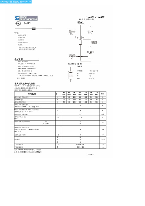
极性:颜色频带为负极
高温焊接防护证:260℃/ 10秒 /.375",设计(9.5mm)引线长度在5 lbs,(2.3千克)张力
重量:0.35克
尺寸以英寸(毫米) 标记图
1N400X G Y WW
=具体设备守则 =绿色复合 =年 =工作周
最大反向电流@额定VRT
满载最大反向电流,完整 周期平均.375"设计(9.5mm)铅Lenfth @T =75℃
典型结电容(注2)
=25 ℃ T =125℃
典型热阻
工作温度范围 存储温度范围
注1:与PW = 300微秒脉冲测试,1%占空比 注2:测量4.0V DC应用反向电压在1 MHz和
符
1N 1N 1N 1N 1N 1N 1N 4001 4002 4003 4004 4005 4006 4007
最大额定值和电气特性
等级25
℃ 环境温度,除非另有规定.
单相,半波,60赫兹,电阻或电感性负载.
对于容性负载,减免电流20%
型号数量
最大重复峰值反向电压
最大RMS电压
最大直流阻断电压 最大正向平均整流电流
.375"设计(9.5mm)引线长度@T =75℃
峰值正向浪涌电流,8.3ms单一正弦半波 叠加额定负荷(JEDEC方法) 额定值融合(t8.3ms) 最大正向电压(注1) @1A
图. 2最大非重复正向
浪涌电流 50
40
CURRENT(A)
30
8.3msSingle Half Wave JEDEC Method
20
PEAK FORWARD SURGE
产品扭矩值、噪音值参数说明

台湾飞特气动工具产品参数说明
尊敬的客户:
您好!
台湾飞特气动工具产品相关参数说明如下:
一、扭矩值
①FW-4SR-1为飞特冲击式气动扳手,正常拧紧螺丝的时间在5秒钟以内时,扭矩范围为8-16N.m。
超过5秒钟后扭矩值会加大。
②FW-4SRD-1、D-10为飞特冲击式气动起子,正常拧紧螺丝的时间在5秒钟以内时,扭矩范围为6-13N.m。
超过5秒钟后扭矩值会加大。
③FW-60SR-1为飞特双气缸油浴式气动扳手,正常拧紧螺丝的时间在5秒钟以内时,扭矩范围为14-26N.m。
超过5秒钟后扭矩值会加大。
④FW-60SRD-1、D-10为飞特双气缸油浴式气动起子,正常拧紧螺丝的时间在5秒钟以内时,扭矩范围为11-20N.m。
超过5秒钟后扭矩值会加大。
二、噪音值
在噪音测量方面,我们遵照ISO15744的标准,噪音值为85分贝,测量等级可增加3dB(A)用以消除生产和测量方法上的偏差。
绝大多数数值均依照Pneurop测试标准得出。
自2002年开始,针对声音测量的官方测试标准更改为ISO15744。
这两个标准之间的区别甚小,在多数情况下可以忽略不计。
在表述上,我们声明噪音级别低,我们是指与性价比不高的类似产品相比较。
在很多实际工位中,生产过程的噪音要远远高于工具无负载时的噪声,因此,通常建议操作者在使用时佩戴听力保护用具。
上海芊华机械有限公司。
QS5K2TR;中文规格书,Datasheet资料
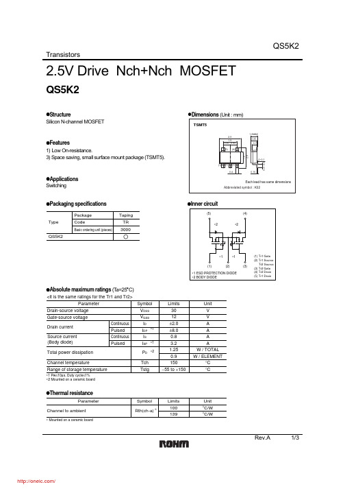
TransistorsRev.A 1/32.5V Drive Nch+Nch MOSFETQS5K2z Structure z Dimensions (Unit : mm) Silicon N-channel MOSFETz Features1) Low On-resistance.3) Space saving, small surface mount package (TSMT5).zSwitchingz Packaging specifications z Inner circuitz Absolute maximum ratings (T a=25°C)∗1∗2∗1ParameterV V DSS Symbol V V GSS A I DA I DP A I SAI SP W / TOTAL P D °C Tch °CTstgLimits Unit Drain-source voltage Gate-source voltage Drain current Total power dissipation Channel temperatureRange of storage temperatureContinuous Pulsed Continuous Pulsed∗1 Pw ≤10µs, Duty cycle ≤1%∗2 Mounted on a ceramic boardSource current (Body diode)30150−55 to +15012±2.0±8.00.83.21.25W / ELEMENT0.9<It is the same ratings for the Tr1 and Tr2>z Thermal resistanceParameter°C/W Rth(ch-a)Symbol Limits Unit Channel to ambient100°C/W139∗ Mounted on a ceramic board∗TransistorsRev.A 2/3z Electrical characteristics (T a=25°C)z Body diode characteristics (Source-drain) (T a=25°C)V SD −−1.2VI S = 3.2A, V GS =0VForward voltage∗ PulsedParameter Symbol Min.Typ.Max.UnitConditions∗<It is the same characteristics for the Tr1 and Tr2>TransistorsRev.A 3/3DRAIN-SOURCE VOLTAGE : V DS (V)101001000C A P A C I T A N C E : C (p F )Fig.1 Typical Capacitancevs. Drain-Source VoltageGATE-SOURCE VOLTAGE : V GS (V)0.0010.010.1110D R A I N C U R RE N T : I D (A )Fig.4 Typical Transfer CharacteristicsSOURCE-DRAIN VOLTAGE : V SD(V)S O U R C E C U R R E N T : I S (A )Fig.6 Source Current vs. Source-Drain VoltageGATE-SOURCE VOLTAGE : V GS (V)100200300S T A T I C D R A I N -S O U R C E O N -S T A T E R E S I S TA N C E : R D S (m Ω)Fig.5 Static Drain-SourceOn-State Resistance vs.Gate source Voltagez Electrical characteristics curvesDRAIN CURRENT : I D (A)1101001000S W I T C H I N G T I M E : t (n s )Fig.2 Switching CharacteristicsTOTAL GATE CHARGE : Qg (nC)123456G A T E -S O U R C E V O L T A G E : V G S (V )Fig.3 Dynamic Input CharacteristicsDRAIN CURRENT : I D (A)S T A T I C D R A I N -S O U R C E O N -S T A T E R E S I S T A N C E : R D S (o n ) (m Ω)Fig.7 Static Drain-Source On-State Resistance vs. Drain Current ( Ι )DRAIN CURRENT : I D (A)S T A T I C D R A I N -S O U R C E O N -S T A T E R E S I S T A N C E : R D S (o n ) (m Ω)Fig.8 Static Drain-Source On-State Resistance vs. Drain Current ( ΙΙ )DRAIN CURRENT : I D (A)S T A T I C D R A I N -S O U R C E O N -S T A T E R E S I S T A N C E : R D S (o n ) (m Ω)Fig.9 Static Drain-Source On-State Resistance vs. Drain Current ( ΙΙΙ )AppendixAbout Export Control Order in JapanProducts described herein are the objects of controlled goods in Annex 1 (Item 16) of Export T rade ControlOrder in Japan.In case of export from Japan, please confirm if it applies to "objective" criteria or an "informed" (by MITI clause)on the basis of "catch all controls for Non-Proliferation of Weapons of Mass Destruction.Appendix1-Rev1.1分销商库存信息: ROHMQS5K2TR。
Fox FT2A 热质量流量计和温度变送器用户手册说明书

Fox FT2A Manuals:• Fox FT2A Modbus / BACnet MS/TP Manual • Fox FT2A Profibus, DeviceNet, Ethernet Manual • Fox FT2A View™ ManualAll Fox Manuals and software available in English only.T H E R M A L I N S T R U M E N T SI N T R O D U C T I O NI N T R O D U C T I O NiSpecial Conditions of Use:• Consult the manufacturer if dimensional information on the flameproof joints is necessary.• Follow the manufacturer's instructions to reduce the potential of an electrostatic charging hazard.I N S T A L L A T I O NiI N S T A L L A T I O NSensor Orientation - Unequal LengthiI N S T A L L A T I O NiG NI RW IiiNote:Serial numbers: If you have more than one meter, you must ensure that the serial numbers of the probe/J-Box, remote electronics, housing, and/or flow body match one another. These items have been manufactured and calibrated to operate as a unit and cannot be mismatched.Keep power and signal wires within the area of the metal shields.Keep power and signal wires out of the unshielded area.W I R I N GCaution:• Supply connection wiring must be rated for at least 90°C.17Caution:• Supply connection wiring must be rated for at least 90°C.W I R I N Gi Important NoteThe load resistor on the Fox Flow Meter 4 to 20mA signal is typically250 ohms and is located in or at the customers PLC or DCS. A 250ohm resistor in the 4 to 20mA line will result in a 1 to 5VDC signal to thePLC or DCS. Some PLC/DCS equipment has the load resistor built in tothe unit; please refer to the PLC/DCS technical manual. Do not exceed a600 ohm load on the Fox Flow Meter 4 to 20mA signal.19iImportant Note:The load resistor on the Fox Flow Meter 4 to 20mA signal is typically 250 ohms and is located in or at the customers PLC or DCS. A 250 ohm resistor in the 4 to 20mA line will result in a 1 to 5VDC signal to the PLC or DCS. Some PLC/DCS equipment has the load resistor built in to the unit; please refer to the PLC/DCS technical manual. Do not exceed a 600 ohm load on the Fox Flow Meter 4 to 20mA signal.W I R I N GiNote:The FT2A Frequency/Alarm output is typically used to drive digital circuitry or solid-state relays. The output of a solid state relay may, in turn, operate loads such as electromechanical relays or alarm indicators.W I R I N GInstallation wiring: Keep the wires inside the FT2A enclosure short. Obtain the correct length for the FT2A remote wires using one of these methods:• Trim the wires to extend 5 inches out of the enclosure after the conduit and wires are routed to the FT2A.• Trim the wires to extend 6 inches from the end of the conduit before it is attached to the FT2AW I R I N GiiiW I R I N G O P E R A T I O NOperation: Start UpStart Up Sequence FT2A DisplayUSB InterfaceO P E R A T I O NO P E R A T I O Ni iiOPE R A TIO NFrequency OutputiPulse per UnitiOPE R A T IO NAlarm Outputi Discrete InputiDisplay SetupOPE R A TIO NO PE R A TIO NiUnits SettingsiOPE R A T IO NFlow Parametersi iO PE R A TIO NO PE R A TIO NiCalibration ParametersOPE R A TIO Nthe Local DisplayiTotalizer RolloveriOPE R A TIO Ni i i iO P E R A T I O N。
哈菲利电磁干扰技术产品目录-EFT说明书

product catalogue: eftPEFT 4010FeaturesOne solution for:IEC/EN 61000-4-4 edition 1 & 2, ETSI 300 386-2, Bellcore-1089/section 9.10.5BenefitsConsistent pulse parametersFully automated byTotally reproducible test resultsPEFT 8010/product_catalogue/eft/index.html[9/24/2012 11:10:33 AM]accessoriesIP4A - Capacitive Coupling ClampThe IP4A is a capacitive coupling clamp for superposition of bursts on data lines in accordance with IEC/EN 61000-4-4.maximum cable size 40mmminimum test cable length 1mmaximum EFT voltage 8kVcoupling plane mounted on 0.1m insulation blockhandy carrying handleconcept, which offers such simplicity of use, that even users with minimum technical experience, will by carrying out tests in no time.This unique software allows users to run user specified or pre-defined tests according to the latest standards, and monitors and displays real time output current and voltage values. The software runs under all latest Microsoft Windows versions and is compatible with all stand alone Haefely EMC test generators.IEEE 488 interfaceGPIB interface board for the PEFT4010 mainframeExternal Warning LampConnected to any generator, the additional, stand-alone widely seen warning lamp indicates clearly the status of the test equipment by red & green lights.External Emergency Stop SwitchConnected to any generator, the EMERGENCY STOP SWITCH, when activated instantly discharges high voltage circuits and switches off power to the EUT.。
SFH 225 FA;中文规格书,Datasheet资料
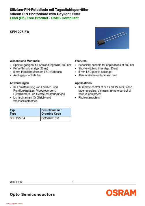
SFH 225 FASilizium-PIN-Fotodiode mit Tageslichtsperrfilter Silicon PIN Photodiode with Daylight FilterLead (Pb) Free Product - RoHS Compliant2007-04-021Wesentliche Merkmale •Speziell geeignet für Anwendungen bei 880 nm •Kurze Schaltzeit (typ. 20 ns)• 5 mm-Plastikbauform im LED-Gehäuse •Auch gegurtet lieferbarAnwendungen•IR-Fernsteuerung von Fernseh- und Rundfunkgeräten, Videorecordern,Lichtdimmern und Gerätefernsteuerungen •Lichtschranken für Gleich- und WechsellichtbetriebTyp Type Bestellnummer Ordering Code SFH 225 FAQ62702P1051Features •Especially suitable for applications of 880 nm •Short-switching time (typ. 20 ns)• 5 mm LED plastic package•Also available on tape and reelApplications•IR-remote control of hi-fi and TV sets, video tape recorders, dimmers, remote control of various equipment •PhotointerruptersGrenzwerte Maximum RatingsBezeichnung Parameter SymbolSymbolWertValueEinheitUnitBetriebs- und Lagertemperatur Operating and storage temperature range Top; T stg– 40 … + 100°CSperrspannung Reverse voltage VR20VVerlustleistung, T A = 25 °C Total power dissipation Ptot150mWKennwerte (T A = 25 °C, λ = 870 nm) CharacteristicsBezeichnung Parameter SymbolSymbolWertValueEinheitUnitFotostrom PhotocurrentV R = 5 V, E e = 1 mW/cm2IP34 (≥ 25)μAWellenlänge der max. FotoempfindlichkeitWavelength of max. sensitivityλS max900nmSpektraler Bereich der FotoempfindlichkeitS = 10 % von SmaxSpectral range of sensitivityS = 10 % of Smaxλ740 … 1120nmBestrahlungsempfindliche FlächeRadiant sensitive areaA 4.84mm2Abmessung der bestrahlungsempfindlichen Fläche Dimensions of radiant sensitive area L×BL×W2.20 × 2.20mm × mmHalbwinkel Half angle ϕ± 60Graddeg.Dunkelstrom, V R = 10 V Dark current IR2 (≤ 30)nASpektrale Fotoempfindlichkeit Spectral sensitivity Sλ0.63A/WQuantenausbeute Quantum yield η0.90ElectronsPhotonLeerlaufspannung, E e = 0.5 mW/cm2 Open-circuit voltage VO330 (≥ 250)mV2007-04-0222007-04-023Kurzschlußstrom, E e = 0.5 mW/cm 2 Short-circuit currentI SC 17μA Anstiegs- und Abfallzeit des Fotostromes Rise and fall time of the photocurrentR L = 50 Ω; V R = 5 V; λ = 850 nm; I p = 800 μA t r , t f20nsDurchlaßspannung, I F = 100 mA, E = 0 Forward voltageV F 1.3V Kapazität, V R = 0 V, f = 1 MHz, E = 0 CapacitanceC 048pF Temperaturkoeffizient von V O Temperature coefficient of V O TC V – 2.6mV/K Temperaturkoeffizient von I SC Temperature coefficient of I SCTC I 0.18%/K Rauschäquivalente Strahlungsleistung Noise equivalent power V R = 10 VNEP3.6 × 10– 14Nachweisgrenze, V R = 10 V Detection limitD*6.1 × 10¹²Kennwerte (T A = 25 °C, λ = 870 nm) Characteristics (cont’d)Bezeichnung ParameterSymbol SymbolWert Value Einheit Unit W Hz -----------cm Hz ×W--------------------------2007-04-024Relative Spectral SensitivityDark CurrentPhotocurrent I P = f (E e ), V R = 5 VCapacitanceTotal Power Dissipation Dark CurrentMaßzeichnungPackage OutlinesMaße in mm (inch) / Dimensions in mm (inch).LötbedingungenSoldering ConditionsWellenlöten (TTW)(nach CECC 00802)2007-04-025OSRAM Opto Semiconductors GmbHWernerwerkstrasse 2, D-93049 Regensburg© All Rights Reserved.The information describes the type of component and shall not be considered as assured characteristics.Terms of delivery and rights to change design reserved. Due to technical requirements components may contain dangerous substances. For information on the types in question please contact our Sales Organization.PackingPlease use the recycling operators known to you. We can also help you – get in touch with your nearest sales office. By agreement we will take packing material back, if it is sorted. You must bear the costs of transport. For packing material that is returned to us unsorted or which we are not obliged to accept, we shall have to invoice you for any costs incurred.Components used in life-support devices or systems must be expressly authorized for such purpose! Critical components 1 , may only be used in life-support devices or systems 2 with the express written approval of OSRAM OS.1 A critical component is a component usedin a life-support device or system whose failure can reasonably be expected to cause the failure of that life-support device or system, or to affect its safety or effectiveness of that device or system.2 Life support devices or systems are intended (a) to be implanted in the human body, or (b) to support and/or maintain and sustain human life. If they fail, it is reasonable to assume that the health of the user may be endangered.2007-04-026分销商库存信息: OSRAMSFH 225 FA。
Datasheet_Flatpack2_48_2000_HE ELTEK通信电源规格书

85-300 VAC (Nominal 176 – 275 VAC)
45 to 66Hz
11.6 Arms maximum at nominal input and full load
> 0.99 at 50% load or more
o Varistors for transient protection o Mains fuse in both lines o Disconnect above 300 VAC
Broadband and network access Increasing network speed demands flexible and expandable DC power solutions. The Flatpack2 HE rectifiers are your key building blocks for future needs.
IEC 60950-1 UL 60950-1 CSA 22.2
EMC
ETSI EN 300 386 V.1.3.2 EN 61000-6-1 (immunity, light
industry) EN 61000-6-2 (immunity, industry) EN 61000-6-3 (emission, light industry) EN 61000-6-4 (emission, industry) Telcordia NEBS GR1089 CORE
Hale Waihona Puke Alarms:o Low mains shutdown o High temperature shutdown o Rectifier Failure o Overvoltage shutdown on output o Fan failure o Low voltage alarm at 43.5V o CAN bus failure
施耐德 RXM2LB2BD RXM插入式继电器 数据表

Product data sheetCharacteristicsRXM2LB2BDRXM小型继电器,2 C/O - 24 V DC - 5 A ,带LED主要信息产品系列Harmony Electromechanical Relays 无干扰线圈无系列号小型产品类型插入式继电器产品短名RXM 触点类型2 OC额定负载电流 壳体内 [Ithe]5 A 在…上 -40…55 °C补充信息触点动作标准控制回路电压 [Uc]24 V DC LED 状态有控制类型无按钮额定冲击耐受电压 [Uimp]4 KV 在 1.2/50 µs 符合 IEC 61810-7额定工作电流 [Ie]5 A (AC-1/DC-1) NO 符合 IEC 2.5 A (AC-1/DC-1) NC 符合 IEC 1 A 在…上 28 V (DC-13) NO最小开关能力25 mW subject to switching frequency, environment or expected reliability level etc 动作时间20 ms 线圈放电和断开延时触头的接通 20 ms 线圈加电和接通延迟触头的接通CAD 总宽度21 Mm CAD 总高度27 Mm CAD 总深度46 Mm最小开关电流 [Imin]5 MA subject to switching frequency, environment or expected reliability level etc 最小开关电压5 V subject to switching frequency, environment or expected reliability level etc 额定操作电压限制19.2...26.4 V DC 额定绝缘电压 [Ui]250 V 符合 IEC 最大开关电压250 V AC 28 V DC 压降阀值>= 0.1 Uc DC 负载电流5 A 在…上 250 V AC 5 A 在…上 28 V DC 最大开关能力1250 VA AC 140 W DC平均电阻640 Ω 在…上 23 °C +/- 10 %平均消耗,单位为W 0.9 W, DC 机械寿命10000000 次电气寿命100000 次 适用 阻性(负载) 量50000 次, 1 A 在…上 28 V, DC-13 NOT h e i n f o r m a t i o n p r o v i d e d i n t h i s d o c u m e n t a t i o n c o n t a i n s g e n e r a l d e s c r i p t i o n s a n d /o r t e c h n i c a l c h a r a c t e r i s t i c s o f t h e p e r f o r m a n c e o f t h e p r o d u c t s c o n t a i n e d h e r e i n .T h i s d o c u m e n t a t i o n i s n o t i n t e n d e d a s a s u b s t i t u t e f o r a n d i s n o t t o b e u s e d f o r d e t e r m i n i n g s u i t a b i l i t y o r r e l i a b i l i t y o f t h e s e p r o d u c t s f o r s p e c i f i c u s e r a p p l i c a t i o n s .I t i s t h e d u t y o f a n y s u c h u s e r o r i n t e g r a t o r t o p e r f o r m t h e a p p r o p r i a t e a n d c o m p l e t e r i s k a n a l y s i s , e v a l u a t i o n a n d t e s t i n g o f t h e p r o d u c t s w i t h r e s p e c t t o t h e r e l e v a n t s p e c i f i c a p p l i c a t i o n o r u s e t h e r e o f .N e i t h e r S c h n e i d e r E l e c t r i c I n d u s t r i e s S A S n o r a n y o f i t s a f f i l i a t e s o r s u b s i d i a r i e s s h a l l b e r e s p o n s i b l e o r l i a b l e f o r m i s u s e o f t h e i n f o r m a t i o n c o n t a i n e d h e r e i n .安全可靠的数据B10d = 100000工作额定值<=1200次/小时 欠载<=18000次/小时 无负荷利用系数20 %绝缘性能2000 V AC 线圈和触头之间 和 基本绝缘 绝缘2000 V AC 极之间 和 基本绝缘 绝缘1000 V AC 触头之间 和 微断 绝缘保护种类RT I污染等级3操作位置任何位置测试水平 A 级 group mounting每件单独销售数量10触点材料银合金(银/镍)净重0.032 Kg环境IP 保护等级IP40 conforming to IEC 60529符合标准IEC 61810-1 (iss. 2)CE贮存环境温度-40…85 °C抗振动 3 gn, 振幅 = +/- 1 mm (f = 10…50 Hz)运行 符合 IEC 60068-2-66 gn, 振幅 = +/- 1 mm (f = 10…50 Hz)非运行 符合 IEC 60068-2-6抗冲击30 gn 适用 非运行 符合 IEC 60068-2-2710 gn 适用 运行期间 符合 IEC 60068-2-27包装单位Unit Type of Package 1PCENumber of Units in Package 11Package 1 Height 2.000 CmPackage 1 Width 2.500 CmPackage 1 Length 4.500 CmPackage 1 Weight33.000 GUnit Type of Package 2BB1Number of Units in Package 210Package 2 Height 3.000 CmPackage 2 Width10.500 CmPackage 2 Length12.500 CmPackage 2 Weight363.000 GUnit Type of Package 3S02Number of Units in Package 3270Package 3 Height15.000 CmPackage 3 Width30.000 CmPackage 3 Length40.000 CmPackage 3 Weight10.065 Kg可持续性产品类型Green Premium 产品REACh法规REACh 声明REACh(不含 SVHC)是欧盟ROHS指令主动合规性(超出欧盟 RoHS 法定范围的产品)欧盟ROHS声明无有毒重金属是无汞是中国 ROHS 管理办法中国 ROHS 声明RoHS 豁免信息是环境披露产品环境文件流通资料产品使用寿命终期信息WEEE该产品必须经特定废物回收处理后弃置于欧盟市场,绝不可丢弃于垃圾桶中。