TLC-JC-GM009 接入网用单纤双向双端口光组件(GPON)检验报告模板 VA.0
项行业标准复审结论

移动通信网应用服务端到端通信密钥管理
继续有效
62.
YD/T 2039-2009
移动通信网应用服务端到端通信认证机制
继续有效
63.
YD/T 849-1996
开放系统互连安全体系结构
继续有效
64.
YDN 126-2009
增值电信业务网络信息安全保障基本要求
继续有效
65.
YD/T 2054-2009
25.
YD/T 206.28-1997
架空通信线路铁件墙壁电缆铁件类
继续有效
26.
YD/T 206.29-1997
架空通信线路铁件电缆交接箱站台
继续有效
27.
YD/T 206.1-1997
架空通信线路铁件通用技术条件
继续有效
28.
YD/T 206.2-1997
架空通信线路铁件线担类
继续有效
29.
YD/T 206.3-1997
继续有效
70.
YD/T 872-1996
数据通信网开放系统互连(OSI)的管理框架
继续有效
71.
YD/T 873-1996
数据通信网开放系统互连(OSI)管理公共管理信息服务定义
继续有效
72.
YD/T 874-1996
数据通信网开放系统互连(OSI)管理公共管理信息协议规范
继续有效
73.
YD/T 949-1998
104.
YD/T 1588.3-2009
光缆线路性能测量方法第3部分:链路偏振模色散
继续有效
105.
YD/T 901-2009
层绞式通信用室外光缆
继续有效
GPON技术(OMCI HGU SFU)简介-20130815

ONU ONU ONU ONU
机房
GbE 1 Gbps 1
1:128 Splitter 1 Gbps 2 1 Gbps N
ONU
ONU ONU
语音接 入平台
PON-OLT
科技创新,融合应用
目录
效果示意图 GPON基本概念篇 GPON ----- SFU篇 GPON ----- HGU篇 GPON ------ OLT篇
科技创新,融合应用
GPON 上下行数据
Ø 下行:时分复用(TDM)广播广播方式,所有的ONU都能收到相同的数据, 通过Gemport ID, ONU来识别、区分和过滤属于自己的数据。
科技创新,融合应用
GPON 上下行数据
Ø 上行:通过TDMA(时分复用)的方式传输数据,上行链路被分成不同的 时隙,根据下行帧的upstream bandwidth map字段来给每个ONU分配上 行时隙,这样所有的ONU就可以按照一定的秩序发送自己的数据了,不 会产生为了争夺时隙而冲突。
SFU:Single Family Unit(单住户单元)型ONU Ø 主要用于单独家庭用户,具备宽带接入终端功能,提供以太网/IP业务, 可选支持CATV业务。具有1或4个以太网接口,可选1个或者2个POTS口,可 选支持CATV RF口。主要应用于FTTH的场景(可与家庭网关配合使用,以 提供更强的业务能力)。 GPON ONU支持两种认证方式: 1. 基于物理标识的认证:采用ONU的物理标识(在GPON系统中,物理标识为 ONU的SN)作为认证标识的认证方法。 备注:Serial number(8 bytes) 2. 基于逻辑标识的认证:采用ONU的逻辑标识作为认证标识的认证方法,逻 辑标识采用LOID + Password。
TLC-JC-GMJD001 小型化可插拔(SFP)光模块检验报告模板(监督) VA.2

报告编号:×××<计量标志> <CNAS标志>检验报告产品型号产品名称小型化可插拔(SFP)光模块申请单位检验类别产品认证监督检验×××××××××检验中心注意事项1.报告无“检验报告专用章”或检验单位公章无效。
2.报告需加盖骑缝章。
3.复制报告未重新加盖“检验报告专用章”或检验单位公章无效.4.报告无主检、审核、批准人签字无效。
5.报告涂改无效。
6.部分复印本检验报告无效7.本检验报告仅对来样负责。
8.对检验报告若有异议,请于收到报告之日起十五日内向泰尔认证中心提出。
地址:××××××邮政编码:××××××电话:××××××传真:××××××网址:××××××E-MAIL:××××××检验报告批准:审核:主检:检验情况一览表检验结果样品信息1 样品信息描述××××××。
{如产品的结构、材质等}2 样品的关键材料信息:见附件3 样品照片{注明样品型号规格}检验使用仪表图XX 常温环境下发射光眼图结果附件样品的关键材料信息报告编号:××××××检测委托书号:×××申请单位:××××××产品名称:×××产品型号:×××材料名称型号生产厂家芯片××××××发光组件××××××接收组件××××××WDM器件×××××××××××检验中心(公章)×××年××月××日。
单模光缆检验报告
单模光缆检验报告一、背景介绍单模光缆是一种传输距离长、带宽高、抗干扰能力强的光通信线路,广泛应用于电信、数据通信和无线通信等领域。
为确保光缆的质量和性能,进行光缆的检验是非常重要的。
二、检验目的本次检验旨在验证单模光缆的传输损耗、带宽、插损和回波损耗等性能指标是否符合设计要求,以保证光缆在实际应用中的可靠性和稳定性。
三、检验方法1.传输损耗检验:采用OTDR(光时域反射分析仪)检测方法,通过发射光脉冲信号,测量被测光缆上的反射和传输损耗。
2.带宽检验:采用差分模式饱和光时域反射测试(DMD-SWEEP)法,通过测量光缆上的差分模时延,计算出光缆的带宽。
3.插损检验:采用光功率计测量法,分别测量光缆的发送端和接收端的光功率,并计算插损值。
4.回波损耗检验:采用回波损耗测试仪进行测量,通过将光信号发送到光缆上,检测返回的光信号的强度,计算回波损耗。
四、检验结果与分析1. 传输损耗:在30km的光缆上进行OTDR检测,测得光纤的传输损耗为0.5dB/km,符合设计要求,证明光缆传输能力强。
2. 带宽:采用DMD-SWEEP法测得光纤的差分模时延为10ps/km,通过计算得出光缆的带宽为100GHz,满足高速数据传输的需求。
3.插损:光缆的发送端和接收端的光功率分别为-3dBm和-5dBm,通过计算得出光缆的插损值为2dB,低于设计要求,保证了光信号的传输质量。
4.回波损耗:通过回波损耗测试仪测得光纤的回波损耗为50dB,超过设计要求的40dB,保证了光信号的稳定传输。
五、结论根据以上检验结果及分析,我们可以得出以下结论:1.单模光缆的传输损耗、带宽、插损和回波损耗等性能指标均满足设计要求。
2.光缆的传输能力强,能够满足长距离数据传输的需求。
3.光缆的插损和回波损耗值低,保证了光信号的传输质量和稳定性。
六、改进建议通过本次检验,我们发现单模光缆的性能符合设计要求1.进一步提高光缆的传输能力,以满足未来高速数据传输的需求。
交换机路由光模块参数

目录第1章可插拔模块简介1.1 H3C中端系列以太网交换机支持的可插拔模块类型1.2 光模块概念介绍1.2.1 简介1.2.2 传输速率(Data Rate)1.2.3 传输距离1.2.4 中心波长1.2.5 光纤类型1.2.6 接口连接器类型1.2.7 接口指标1.3 电口模块概念介绍1.3.1 千兆电口模块简介1.3.2 10G电口模块简介第2章 SFP模块2.1 千兆SFP光模块2.1.1 外观图2.1.2 具体型号及规格2.2 百兆SFP光模块2.2.1 外观图2.2.2 具体型号及规格2.3 千兆/百兆BIDI模块2.3.1 外观图2.3.2 具体型号及规格2.4 BIDI GEPON OLT光模块2.4.1 外观图2.4.2 具体型号及规格2.5 千兆CWDM模块2.5.1 外观图2.5.2 具体型号及规格2.6 SFP电口模块2.6.1 外观图2.6.2 具体型号及规格第3章 GBIC模块3.1 GBIC光模块3.1.1 外观图3.1.2 具体型号及规格3.2 GBIC电口模块3.2.1 外观图3.2.2 具体型号及规格第4章 XFP模块4.1 外观图4.2 具体型号及规格第5章 XENPAK模块5.1 XENPAK光模块5.1.1 外观图5.1.2 具体型号及规格5.2 XENPAK LX4光模块5.2.1 外观图5.2.2 具体型号及规格5.3 XENPAK CX4电口模块5.3.1 外观图5.3.2 具体型号及规格第1章可插拔模块简介1.1 H3C中端系列以太网交换机支持的可插拔模块类型H3C中端系列以太网交换机支持的可插拔模块类型如表1-1所示。
表1-1 可插拔模块类型说明:●H3C中端系列以太网交换机的不同产品可支持的可插拔模块类型不同,具体请参见各产品安装手册。
可插拔模块的种类随着时间变化有更新的可能性,所以,若您需要准确的模块种类信息,请咨询H3C公司市场人员或技术支援人员。
TLC-JC-PXJD014 光缆终端盒检验报告模板(监督) VB.0-150507

报告编号:×××<计量标志> <CNAS标志>
检验报告
产品型号
产品名称光缆终端盒
申请单位
检验类别产品认证监督检验
×××××××××检验中心
注意事项
1.报告无“检验报告专用章”或检验单位公章无效。
2.报告需加盖骑缝章。
3.复制报告未重新加盖“检验报告专用章”或检验单位公章无效.
4.报告无主检、审核、批准人签字无效。
5.报告涂改无效。
6.部分复印本检验报告无效。
7.本检验报告仅对来样负责。
8.对检验报告若有异议,请于收到报告之日起十五日内向泰尔认证中心提出。
地址:××××××
邮政编码:××××××
电话:××××××
传真:××××××
网址:××××××
E-MAIL:××××××
检验报告
批准:审核:主检:
检验情况一览表。
J DSU 4000平台快速卡:FiberComplete 双向IL ORL和单向OTDR测量说明书
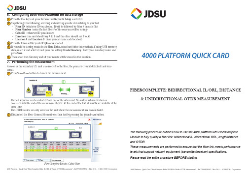
6. Confi guring both 4000 Platforms for data storagePress the F ILE key and press the lower softkey until Setup is selected.Step through the following, selecting and entering specifi c data relating to your test -Fiber ID (whatever ID you choose. It will be followed by Fiber # on each fi le) -Fiber Number (enter the fi rst fi ber # of the ones you will be testing)-Cable ID (whatever ID you choose)-Direction (one unit should say A to B and the other should say B to A)-Location A and Location B(here you can name each location)Press the lower soft key until Explorer is selected.If you will be storing results in the Hard Drive, select hard drive (alternatively, if using USB memorystick, insert it and select it) and press the softkey Create Directory. Enter your directory name andpress Save.Then select that directory and all your results will be stored in that location.7. Performing the measurementAs soon as the secondary (2) unit is connected to the fi ber, the primary (1) unit detects it (and vice-Press S TART/S TOP button to launch the measurement.The test sequence can be initiated from one or the other unit. No additional intervention isnecessary until the end of the measurement cycle. At the end of the test, all results are available at thesame time.The OTDR results are only saved on the unit where the measurement has been initiated.Disconnect the fi ber. Connect the next one, then test by pressing the green S TART button.FiberComplete Results: Cable View4000 PLATFORM QUICK CARDFIBERCOMPLETE: BIDIRECTIONAL IL/ORL, DISTANCE& UNIDIRECTIONAL OTDR MEASUREMENTThe following procedure outlines how to use the 4000 platform with FiberCompleteModule to fully qualify a fi ber link: bidirectional IL, bidirectional ORL, length/distanceand OTDR.These measurements are performed to ensure that the fi ber link meets performancelevels that support network equipment (transmitter/receiver) specifi cations.Please read the entire procedure BEFORE starting.1. Inspect and clean connectorsBefore connecting a fi ber into a test module, inspect and clean the module bulkhead and the fi ber jumper connectors.-Use standard single fi ber patch cords. -Use video inspection scope / probe to inspect connector endfaces for dirt and/or damage. Inspect ALL connectors including bulkheads and test ports2. Connect and turn both units onConnect a fi ber jumper to the main module port of each product.Press the O N /O FFhard key to turn both units on and wait the completion ofauto-test (~ 45 seconds).3. Activate the FiberComplete function on both productsPress the H OMEhard key and use the arrow keys or touchscreen to select the Fiber Completefunction (doesn’t display Fiber Complete until you select it) .Home pagePress R ESULT or ENTER hard key to go to the FiberComplete result page.4. Perform the referencingThe Power Meter option is mandatory onto the 4000 Mainframe.Press R ESULTS buttonPress the soft key References and then Take Refs and follow the step by step instructions to perform references on each unit.Choose Loopback for your loss referencing method.The loopback referencing is used when the two units are at different location. After clicking on, the wizard will guide you through two steps:The self reference is used for loss and ORL testing. Connect the jumper from the module port to themainframe powermeter and press Ok to start referencing.Power meter of the 4000 Base-UnitMTS/T-BERD 4000 (1)Power meter of the 4000 Base-UnitMTS/T-BERD 4000 (2)The reference values are stored and displayed at the endThe zero ORL reference is necessary for ORL testing. Once the self reference measurement has beencarried out, the Zero ORL adjustment can be performedConnect the jumper from the module port to the non-refl ective termination via a mating sleeve. If you don’t have a non-refl ective termination, a mandrel can be used. Press Ok to start referencing.Non refl ective termination(or mandrel)Source of the module5. Confi guring both 4000 Platforms to perform the measurementPress the S ETUP key and set the Acquisition parameters to:-Laser: 1310 & 1550 nm -ORL Measurement: Bidir. -Loss Measurement: Bidir. -Length Measurement: Y es -OTDR Measurement: Auto Set Results Screen to:-Table View Cable or Fiber depending on what is being tested.-Thresholds User 1: defi ne your own thresholds at each wavelength based on your network requirements for Loss and ORL.FiberComplete Setup menu。
FIBER
WP-TEST-FIBER-400 Optical Light Source Owner’s ManualContentsChapter 1: Standard Configuration----------------------------------------------------------------------- 2 Chapter 2: Overview ----------------------------------------------------------------------------------------- 2Features ---------------------------------------------------------------------------------------------------------- 2 Chapter 3: Specifications ------------------------------------------------------------------------------------ 3 Chapter 4: Function ------------------------------------------------------------------------------------------ 44.1F ront ------------------------------------------------------------------------------------------------------------ 4 4.2 Left Side ----------------------------------------------------------------------------------------------------- 5 4.3 Top--------------------------------------------------------------------------------------------------------------------- 6 4.4 Back----------------------------------------------------------------------------------------------------------- 7Chapter 5: Operation Instruction ------------------------------------------------------------------------ 85.1 Types of Power Supply --------------------------------------------------------------------------------- 8 5.2 Powering On the Laser Source-------------------------------------------------------------------- 10 5.3 Backlight Setting --------------------------------------------------------------------------------------- 10 5.4 Output Power ---------------------------------------------------------------------------------------------- 11 5.5 Wavelength Automatic Identification------------------------------------------------------------ 13 5.6 Frequency Detection ---------------------------------------------------------------------------------- 14 5.7 Power Off ------------------------------------------------------------------------------------------------ 15Chapter 6: Troubleshooting ----------------------------------------------------------------------------- 15 Chapter 7: General Maintenance------------------------------------------------------------------------- 15 Chapter 8: Quality Warranty--------------------------------------------------------------------------------- 16Chapter 1: Standard ConfigurationNo.NameQty 1 Optical Light Source1 2 User Manual 1 3 1.5V AA battery 3 4 Power Supply Unit 1 5 Cotton Swabs 1 6 Carry Bag1Chapter 2: OverviewThis handheld optical light source is designed for fiber optic network installation, acceptance, andmaintenance. Used with the matched optical power meter , it can provide an accurate fiber network solution. According to the client’s requirements, it can provide 1-4 wavelengths with stable output power and features continuous adjustable output power. The intelligent backlight control function reduces power usage. The optical light source has a rugged appearance and comfortable design to clients’ requirements.Features●Wave ID information can be transmitted when used with the matched optical power meter .●Tone generation: 270HZ, 330HZ, 1KHZ, 2KHZ ●Adjustable output power●Output power value is shown on LCD display ●Intelligent backlight control (light intensity can be adjusted according to ambient light, greatly reducing power consumption)●AA alkaline batteries and AC adapter for power supply ●Low battery indicatorChapter 3: SpecificationsModel Optical Light SourceOperating wavelength (nm) 850/1300/1310/1550Applicable fiber SM ,MMLaser type FP-LDMaximum Output Power (dBm) -5 (adjustable)Adjustable step size (dBm) <0.5 (adjustable between -5-12dBm) Stability (dB, 15min, 20° C) ±0.1Stability (dB, 30min, 20° C) ±0.05Modulation (Hz) CW, 270,330,1K,2K Fiber Port FC/PC or FC,SC,ST interchangeable Alkaline Battery 3*AA,1.5VPower Supply Adaptor(V) 8.4Battery Operating time(h) 45Operation Temperature (Ԩ) -10 - +60Storage Temperature (Ԩ) -25 - +70Outline size(mm)/weight 175*90*44.5/255gChapter 4: Function4.1 Front(1)(2)(3)4-1(1)Power SwitchPress to turn unit on or offAuto Shut-Off Selection: Quick press to turn the auto shut-off on or off. When active, the unit will automatically shut off after 10 minutes idle. Once selected, “auto-off” will display on the bottom left of the screen. Auto Shut-Off is the default setting.(2)Wavelength SelectionPress to activate laser, then press to select the wavelength. The currentwavelength displays on the top left of the screen.(3)Backlight control. THE LIGHT SOURCE has two types of backlight control.Press to select:“LDR:” intelligent backlight control mode. Power meter will turn on/off the backlight within15 seconds based on exterior lighting. This is the default mode.Back light control key mode. Press to turn the backlight on or off.(4)Rated power: Rated output power(5) D ecrease: Press to decrease the rated output power.(6)Modulation adjustment/wavelength identification: Laser on. After turning on the unit, press, to select laser as the light source. Quickly pressto adjust the frequency (270, 330, 1K, 2KHz). In most instances, this will be set to 0Hz. Press and hold to enter/exit wavelength identification mode. Mode will display on the top right of the screen. “--AU” displays when wavelength identification mode is active. (7)output power: Press to increase the output power(8)“B/L SET”: Backlight indicatorIndicates the backlight control mode. When the indicator is green, “LDR” (Intelligent back light control mode) is active. When the indicator i s red, the backlight is in key control mode.(9)“LDR” Intelligent backlight controllerIn the intelligent backlight control mode, the controller will automatically adjust the backlight to the ambient light in order to save power.(10)ScreenDisplays data and the instrument’s working mode.4.2 Left Side4‐2Connect the AC adaptor to the port.AC adaptor4.3 Top4-3(1)Dust capPlace the dust cap over the connectors when not in use to protect the optical connector.(2)Optical ConnectorThe standard of this optical connector is SC/PC(4-4). It connects to the SC/PC adaptor.Note: small amounts of dust on the connector will affect the accuracy of themeasurement. Use isopropyl alcohol and a cotton swab to clean the connector. Moisten the cotton swab with alcohol, insert the cotton swab in the connector, slightly rotating the cotton swab. Dry using a second dry cotton swab (4-4).Cotton Swab4-4(1) (2)4.4 Back(1)(2)(3)4-64-6(1)LabelContent includes function and instrument information(2)BracketCollapsible metal bracket can be adjusted 0-90 degrees(3)Battery PackHolds 3 1.5AA batteries.Note: When inserting the batteries, note their positive (+) and negative (-)connector orientations. The negative battery connector should be against the spring. Recycle used batteries.Chapter 5: Operation5.1 Types of Power SupplyThe light source can be either battery-powered or AC adaptor-powered, giving total flexibility for most testing sites and situations.5.1.1 AA batteryWhen using AA battery, will display on the left top of the screen (fig.5-1)Battery Power indicator5-1There are five grades of battery power indication:70%-100% power40%-70% power30%-40% power20%-30% powerLess than 20%, the power meter will shut down.Replace batteries. Refer to below figure 5-25-2Push the clip fastener on the battery compartment cover down. Remove the battery compartment cover and remove all three batteries, making a note of their positive and negative orientation. The negative battery connector should be against the spring. Insert 3 new 1.5VV AA batteries. Refit the battery compartment cover. The clip fastener should click shut.Note: Insert the batteries with their positive and negative connectors correctlyaligned.5.1.2 Power Supply UnitWhen the battery is empty, the power supply unit can be used. At the top left of the screen, a will be displayed (5-3). W hen the battery is in the power meter and still charged, the tester will default to the AC power supply.AC power supply5-3When using the AC adaptor, connect the power plug (pictured) and insert it in the AC adapter port AC adaptorPower SupplyPower Plug5-4Note: Only use the power supply unit supplied with the tester. Using another type of power supply may damage the instrument.5.2 Powering On the Laser SourceInsert the battery or the PSU and press on the tester. At this time the laser is still off. The display will show no data, as shown in figure 5-5.Battery indicator Laser off Selected wavelengthPower saving mode (Auto-off)5-5When the tester is in standby, press key to enable/disable auto-off function. If auto-off function is selected, “Auto-off” will display on the bottom left of the screen.5.3 Backlight SettingAfter turning on the optical power meter, press and hold Choose backlight control mode.5.3.1 “LDR” Intelligent backlight control modePress and hold when “B/L SET” is green (5-6). After 10 seconds, the green indicator will turn off. In LDR, the controller will automatically adjust the backlight to ambient light within 15 seconds to save power.Indicator (Green)5-65.3.2 Key control backlight modePress and hold. “B/L SET” (indicator will turn red (5-7)) to enter key control backlight mode.After 10 seconds the indicator will turn off. Quick press to turn the backlight ON/OFF.Indicator (red)5-75.4 Output PowerNote: A warm-up period of 5 minutes or less is normally required to ensure stable output power for the laser source.5.4.1 Open the dust cap and connect the patch cord .Note: Make sure the connector and the end of the patch cord are clean. Make sureto connect the correct type of patch cord.5.4.2 Activating laser light source.When turning on the light source , the laser source is still off. Only after pressing orcan the laser activate on the diode (5-8 & 5-9)5-8 Pressto activate laser on the diodeLaser offLaser on (output wavelength 1310nm; rated output power-5.00dBm; 0Hz: no frequency set.)5-9 : Pressto laser on the diodeNote: To avoid risk of serious eye damage, do not look into the interface at any time5.4.3 Selecting the wavelengthPress to select the output wavelength. It will display at the top of the screen (fig. 5-10)5-105.4.4 Output powerEvery selected wavelength can adjust the output power within range (-5 - -12dBm) and can also load the output frequency. Press to decrease the output power. Press to load the output frequency, (5-11. Fig. 5-13)5-11Laser on (output wavelength 1310nm; rated output power-5.00dBm; 270Hz frequency)Laser off5-12 Press to decrease the output power5-13 Press to load the frequencyFollowing the same principle, press to increase the output power and to load the output frequency.5.5 Automatic Wavelength Identification●Connect the light source with the matched optical power meter.●Enable light source under “Wave ID” operation mode. Press or on lightsource to laser on its matched power meter. Hold down for few seconds. Light source will enter Wave ID mode. “--AU” will be shown on the upper right of the LCD screen.●Enable power meter under “Wave ID” operation mode: Hold down for fewseconds. Power meter will enter Wave ID mode. “--AU”will be shown on the upperright of the LCD screen.●Once the ID information is changed on light source (press to change wavelength),after 3 to5 seconds the detected information on the optical power meter will automaticallyupdate to match. Refer to figure 5-14.●Exit Wave ID mode: Hold down again to exit Wave ID mode on power meter andhold down again to exit Wave ID mode on light sourceLight Source5-145.6Frequency Detection●Connect the light source with its matched power meter.●Output frequency from the optical light source: Press or to releaselight from the unit. Press quickly. The light source will output frequencies of 270Hz, 330Hz,. 1KHz, or 2KHz accordingly, which will display on the upper right of the LCDscreen. In the meantime, THE MATCHED OPTICAL POWER METER will detect thecorresponding frequency automatically from the light source. Refer to figure5-15.Light Source5-15Note: Frequency ID and wave ID cannot be operated at the same time.To avoid risk of serious eye damage, do not look into the optical port of the laser source at any time.850nm (xxdBm)1300nm (xxdBm)1310nm (xxdBm)1550nm (xxdBm)5.7Power OffAuto-Off Function When auto-off function is activated, the unit will turn itself off automatically after 10 minutes idle, regardless of power supply type.Manual power off: Under any operation mode, hold down for a few seconds to turn the unit off. Note: With either power setting, the unit will store the last calibration wavelength and backlight control mode automatically. This will be the default setting when the unit is next turned on. Chapter 6: TroubleshootingProblems Possible cause SolutionFaint display on the LCD screen 1. Power is off2. The batterypower is too low1. Press key.2. Change the batteriesWhen on the lasersource, the outputpower is not stableAllow 15 minute warm-up Chapter 7: General Maintenance7.1 Always ensure the connector ports of the laser source are clean.7.2 Only used the supplied adaptor.7.3 Place dust-proof cap over optical connectors when not in use7.4 Carefully connect/disconnect fiber connectors/adapters to avoid scratches on the port of thepower meter.7.5 Regularly clean the optical port of power meter. Clean according to instructions.Chapter 8: Quality WarrantyDetails of warranty terms and conditions are given as below:1) The company warrants that the light source will be free from defects in material andworkmanship for a period of 18 months. The date will be started from the date of goods shipment.2) If any faults occur due to quality problems of the product during the warranty period,the company promises to repair or replace free of charge. The freight cost and related taxes will be shared by both parties. The company will pay the shipping cost from the customer side to our factory and pay any related import taxes. Customer will pay the shipping cost from our factory to customer side and its local import taxes accordingly.3) This warranty is limited to defects in workmanship and materials and does not coverdamages from accident, acts of god, neglect, wrong usage or abnormal conditions of operation.4) The company. will charge corresponding fees for the cost of materials, repair andshipping in conditions of below:∙Defects occurred under normal use and service but out of the warranty period.∙Failures and damage occurred not because of defects in material and workmanship of products.∙Failures and damage occurred because of failing to comply with the operation instructions.∙Abnormal conditions of operation or handling such as artificial damage, or operating in abnormal conditions such as high temperatures, high voltage,humidity, etc. We will charge according to the actual failure rating.。
- 1、下载文档前请自行甄别文档内容的完整性,平台不提供额外的编辑、内容补充、找答案等附加服务。
- 2、"仅部分预览"的文档,不可在线预览部分如存在完整性等问题,可反馈申请退款(可完整预览的文档不适用该条件!)。
- 3、如文档侵犯您的权益,请联系客服反馈,我们会尽快为您处理(人工客服工作时间:9:00-18:30)。
○
合 格
24
光纤保持力试验后复测
外观
○
合 格
25
输出光功率变化量
○
合 格
26
接收灵敏度变化量
○
合 格
27
光纤扭力试验后复测
外观
○
合 格
28
输出光功率变化量
○
合 格
29
接收灵敏度变化量
○
合 格
检验结 果
序号
检验项目
单位
标准要求
检验结果
结论
1
外观
——
外壳无破裂、无裂纹
发射端参数
2
工作波长范围
×××
×××
×××××检验中心(公章)
××× 年×× 月 ×× 日
报告编号:×××
<计量标志> <CNAS标志>
检 验报告
产品型号
产品名称接入网用单纤双向双端口光组件(GPON)
申 请单位
检验类别产品认证初次/复评检验
×××××××××检验中心
注意事项
1.报告无“检验报告专用章”或检验单位公章无效。
2.报告需加盖骑缝章。
3.复制报告未重新加盖“检验报告专用章”或检验单位公章无效.
产品名称
接入网用单纤双向双端口光组件(GPON)
产品型号/
规格
×××
申请单位
××××××
出厂编号/
生产日期
×××
生产单位
××××××
检验类别
产品认证初次/复评检验
生产地址
××××××
送样日期
×××年××月××日
送样者
×××
样品基数
×××
样品数量
×××
样品初始
状态
样品初始状态完好,符合检验要求
检验依据
4.报告无主检、审核、批准人签字无效。
5.报告涂改无效。
6.部分复印本检验报告无效
7.本检验报告仅对来样负责。
8.对检验报告若有异议,请于收到报告之日起十五日内向泰尔认证中心提出。
地址:××××××
邮政编码:××××××
电话:××××××
传真:××××××
网址:××××××
E-:××××××
检验报告
YD/T 1998.2-2009《接入网用单纤双向双端口光组件技术条件第2部分:用于吉比特无源光网络(GPON)的光组件》
YD/T 1995-2009《接入网设备测试方法-吉比特的无源光网络(GPON)》
检
验
结
论
该公司的×××产品经检验,结果如下:
应测项目×项;
实测项目×项;
无关项×项;
不合格项××项(B类××项;C类××项)。
dB
≤1
21
变频振动试验后复测
外观
——
外壳没有破裂、没有裂纹,组件内部的元器件没有发生脱落;
22
输出光功率变化量
dB
≤1
23
接收灵敏度变化量
dB
≤1
24
光纤保持力试验后复测
外观
——
外壳没有破裂、没有裂纹,组件内部的元器件没有发生脱落;
25
输出光功率变化量
dB
≤1
26
接收灵敏度变化量
dB
≤1
27
光纤扭力试验后复测
×××年××月××日至××日
检验环境条件
温度:(××~××)℃
相对湿度:(××~××)%
检验人
×××
校核人
×××
附件
样品的关键材料信息
报告编号:××××××检测委托书号:×××
申请单位:××××××
产品名称:×××
产品型号:×××
材料名称
型号
生产厂家
发光组件
×××
×××
接收组件
×××
×××
尾缆及连接器插头
○
合 格
2
OLT发射端参数
工作波长范围
○
合 格
3
输出光功率
○
合 格
4
RMS光谱宽度
○
合 格
5
-20dB光谱宽度
○
合 格
6
边摸抑制比
○
合 格
7
阙值电流
○
合 格
8
正向电压
○
合 格
9
背光监视电流
○
合 格
10
跟踪误差
○
合 格
11
光回波损耗
○
合 格
12
ONU接收端参数
工作波长范围
○
合 格
13
接收灵敏度
○
合 格
nm
3
输出光功率
mW
4
RMS光谱宽度
nm
5
-20dB光谱宽度B
nm
≤1
6
边摸抑制比
dB
≥30
7
阙值电流
mA
常温,≤
Tc=70℃,≤35
Tc=85℃,≤50
8
正向电压
V
≤1.6
9
背光监视电流
mA
0.1~1.5
10
跟踪误差
dB
-1.5~+1.5
11
光回波损耗
dB
接收端参数
12
工作波长范围
nm
13
接收灵敏度
外观
——
外壳没有破裂、没有裂纹,组件内部的元器件没有发生脱落;
28
输出光功率变化量
dB
≤1
29
接收灵敏度变化量
dB
≤1
环境和机械性能试验条件
序号
试验项目
试验条件
1
机械冲击试验
加速度500g,脉冲持续时间1.0ms,5次/轴向
2
变频振动试验
频率:20Hz~2000Hz;加速度:20g;扫频速率:4min/循环;循环次数:4循环/轴向,方向:X、Y、Z
2样品的关键材料信息:
见附件
3样品照片
{注明样品型号规格}
检 验 使 用 仪 表
序号
仪器设备
型号
编号
备 注
1
×××
×××
×××
×××
2
3
4
5
6
7
检验说明:
1.本检测中涉及的分包检测机构:×××,分包检测报告编号:××。
分包检测报告附后。
2.其他需要说明的事项
{如关键部件免检说明等}
测试地点
×××
测试时间
14
饱和光功率
○
合 格
15
光回波损耗
○Байду номын сангаас
合 格
16
组件参数
光串扰
○
合 格
17
隔离度
○
合 格
检 验 情 况 一 览表
序号
检验项目
不合格分类
结论
B类C类
18
机械冲击试验后复测
外观
○
合 格
19
输出光功率变化量
○
合 格
20
接收灵敏度变化量
○
合 格
21
变频振动试验后复测
外观
○
合 格
22
输出光功率变化量
○
合 格
23
dBm
检验结 果
序号
检验项目
单位
标准要求
检验结果
结论
接收端参数
14
饱和光功率
dBm
15
光回波损耗
dB
≥20
组件参数
16
光串扰
dB
≤-45
17
隔离度
dB
≥35
机械环境试验
18
机械冲击试验后复测
外观
——
外壳没有破裂、没有裂纹,组件内部的元器件没有发生脱落;
19
输出光功率变化量
dB
≤1
20
接收灵敏度变化量
3
光纤保持力试验
涂覆层或紧套光纤:拉力5N,保持时间1min
松套或增强性光纤:拉力10N,保持时间1min
4
光纤扭力试验
涂覆层光纤、紧套或松套光纤:扭折力5N,10次循环,扭折点离器件3cm
增强性光纤:扭折力10N,10次循环,扭折点离器件3cm
以下空白
样品信 息
1样品信息描述
××××××。{如产品的结构、材质等}
综合判定:该样品检验结论为×××。
(检验报告专用章)
签发日期:××××年××月××日
备注
1.检验任务依据:泰尔认证中心检测委托书第×××号, TLC《光模块认证实施规则》(V×. ××)
2.再分包检验项目名称用*号表示。
批准:审核:主检:
检 验 情 况 一 览表
序号
检验项目
不合格分类
结论
B类C类
1
外观