台湾天二FCR系列贴片保险丝电阻选型手册
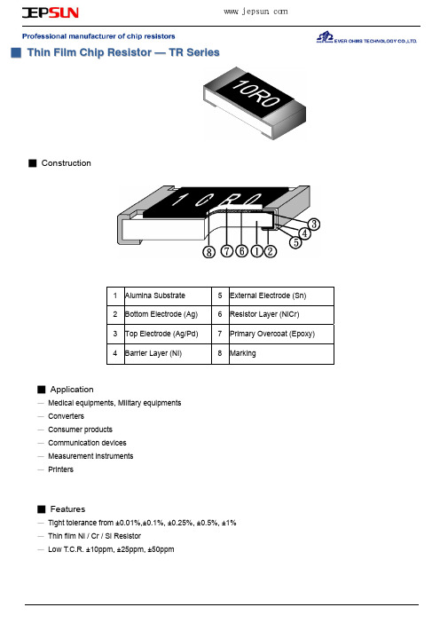
台湾天二TR系列1812贴片薄膜电阻选型手册
■ Top Adhesive Peel Off Strength:10~70g
■ Package
Inner Box Size Reel 1 2 3 5 10 Size H(mm) 13 24 36 60 113 Contain (Kpcs) 25K 50K 150K 300K External Box Size Length (mm) 180 180 430 400 Width (mm) 180 180 200 400 Height (mm) 60 110 200 200
深圳捷比信--高品质精密元件供应商
www.jepsun.com
■ Appendix For SMD Chip Resistor
● Packaging Information
◆ For All Series
■ Dimension
Unit: mm
TYPE 7” 0402 13” 13” 0603 0805 1206 1210 2010 2512 1812 1218 7” 10” 13” 7” 7”
2.0±0.05 0.45±0.10 2.0±0.05 0.60±0.10 2.0±0.05 0.75±0.10 1.50 -0 2.0±0.05 0.75±0.10 2.0±0.05 0.75±0.10
4.0±0.1
■ Dimension
Packaging Type A B W E F G H T
www.jepsun.com
■ Type Dimension
TR0402 / TR0603 /TR0805 / TR1206 / TR1210 / TR1812 / TR2010 / TR2512
TR1218
■ Dimension
台湾天二汽车级贴片电阻QR系列规格书

Resistance Range (mΩ)
F(±1%)、J±(5%)
470~990 100~330 331~990
10~50 51~100 101~990 10~50 51~100 101~990 10~50 51~100 101~990 10~50 51~100 101~990 10~50 51~100 101~990 10~50 51~990 10~50 51~100 101~990
l2 0.20 ± 0.10 0.30 ± 0.10 0.40 ± 0.15 0.50 ± 0.20 0.50 ± 0.20 0.70 ± 0.20 0.60 ± 0.20 0.50 ± 0.20 0.60 ± 0.20
QR-Series Automotive Chip Resistor Product Specifications
QR-Series Automotive Chip Resistor Product Specifications
Document No. S-10-12-20-02
Released Date 2019/03/12
Page No.
5/13
● Automotive High Ohm Chip Resisto
-
Resistance Range F(±1%) G±(2%)
J(±5%) K(±10%)
1Ω~9.9Ω
-
10Ω~990Ω
10Ω~1MΩ
1KΩ~10MΩ
-
1Ω~9.9Ω
-
10Ω~10MΩ
10Ω~1MΩ
10Ω~10MΩ
-
-
1Ω~9.9Ω
-
10Ω~10MΩ
10Ω~1MΩ
10Ω~10MΩ
台湾天二大阻值合金采样电阻TGL系列选型规格书
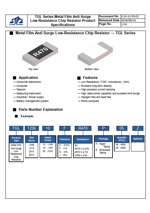
■Metal Film Anti-Surge Low-Resistance Chip Resistor — TGL SeriesTop view Bottom view■Application█Features— Consumer electronics — Low Resistance / TCR / Inductance(≦5nH)— Computer — Excellent long-term stability— Telecom — High precision current sensing— Measuring instrument — High rated power capability and excellent Anti-Surge — Industrial / Power supply — Halogen free and lead free— Battery management system — RoHs compliant■Parts Number Explanation■Example:Final Milestone DateCheckpointTGL1206F R470P05Size (Inch) 1206 1210 2010 2512ToleranceD:±0.5%F:±1%G:±2%J:±5%PackageP:PaperT apingE:EmbossedT apingQuantity(PCS)04:400005:5000ZOptionalProductTypeMetal Film Anti-SurgeLow-ResistanceChip ResistorsResistanceEX.R470=0.47Ω4R70=4.7Ω47R0=47Ω10RatedPower10:1.0W15:1.5W20:2.0W■Standard Electrical SpecificationsType RatedPowerat 70℃Max.RatedCurrentMax.OverloadCurrentT.C.R.(ppm/℃)Resistance RangeD(0.5%), F(1.0%), G(2.0%), J(5.0%)TGL1206 1W 3.16A 7.07A±50 100 mΩ ≦R ≦50 ΩTGL1210 1W 3.16A 7.07ATGL2010 1.5W 3.87A 8.66A±50 100 mΩ ≦R ≦50 ΩTGL2512 2W 4.47A 10.00A● For non-standard parts, please contact our sales dept.● Operating Temperature Range :−55℃〜+155℃.■Anti-Surge Ability:■Type Dimension■Construction Unit:mmTYPE L W H I1I2 TGL1206 3.10±0.10 1.60±0.10 0.55±0.10 0.40±0.20 0.45±0.20 TGL1210 3.10±0.10 2.50±0.15 0.55±0.10 0.50±0.20 0.50±0.20 TGL2010 5.00±0.20 2.50±0.15 0.55±0.10 0.60±0.25 0.60±0.25 TGL2512 6.30±0.20 3.20±0.20 0.55±0.10 0.65±0.25 0.65±0.25①Alumina Substrate ⑥Top Protective Overcoat②Resistive Layer ⑦Marking③Bottom Inner Electrode (Cu) ⑧Side Inner Electrode④Top Inner Electrode ⑨Barrier Layer (Ni)⑤Bottom Protective OvercoatWhite⑩Solder coating (Sn)■ Perfo r mance CharacteristicsPower Derating Curve ■The Operating Temperature Range: -55°C ~+155°C.Power rating or current rating is in the case based on continuous full-load at ambient temperature of 70℃. For operation at ambient temperature in excess of 70℃, the load should be derated in accordance with figure of derating Curve.■ Rated CurrentResistance Range: ≦ 1ΩRated Current: The resistor shall have a DC continuous working current or a AC (rms) continuous working current at commercial-line frequency and wave form corresponding to the power rating, as determined formula as following:I = Rated current (A) P= Rated Power (W) R= Resistance(Ω)■ Rated VoltageResistance Range: > 1ΩRated Voltage: The resistor shall have a DC continuous working voltage or a RMS AC continuous working voltage at commercial-line frequency and wave form corresponding to the power rating, as determined formula as following:V = Rated voltage (V)V = √P ×R P = Rated power (W)R = Nominal resistance (Ω)-5520406080100020406080100120140155℃Ambient Temperature (℃)Power Ratio(%)DERATING CURVE70160■Reliability Test and RequirementTest Item Test Method Procedure Requirements TemperatureCoefficient of Resistance(T.C.R) JIS C 5201-1clause 4.8TCR +125 ℃, 25 ℃is the reference temperatureRefer to StandardElectrical SpecificationsShort Time Overload JIS C 5201-1clause 4.135 times rated power for 5 seconds. ±(1.0%+0.001Ω)Insulation Resistance JIS C 5201-1clause 4.6100V for 1 minute. ≧10GΩDielectric Withstanding Voltage JIS-C5201-1clause 4.71206、1210、2010、2512 for 500 VAC 1minNo short or burned on theappearance.Core Body Strength JIS-C5201-1clause 4.15Central part pressurizing force:10N , 10 seconds No brokenSolderability JIS C 5201-1clause 4.17245±5°C for 3±0.5secs.>95% CoverageNo Visual damageResistance to Soldering Heat JIS-C5201-1clause 4.181. Molten solder, 260±5 °C,10±1 seconds immersion time2. IR reflow, refer to solder reflow temperature condition±(1.0%+0.001Ω)No Visual damageLeaching JIS-C5201-1clause 4.18260±5℃for 30 seconds.>95% CoverageNo Visual damageTemperature Cycling JIS C 5201-1clause 4.19-55℃to +155℃, 300 cycles±(1.0%+0.001Ω)No Visual damageLoad Life in Humidity JIS C 5201-1clause 4.2440±2℃, 90~95% R.H. , Rated power or Max. workingcurrent whichever is less for 1000 hrs with 1.5 hrs〝ON〞and 0.5 hr〝OFF〞.±(1.0%+0.001Ω)Load Life (Endurance) JIS C 5201-1clause 4.2570±2℃, Rated power, or Max. working current whichever isless for 1000 hrs with 1.5 hrs〝ON〞and 0.5 hr〝OFF〞.±(1.0%+0.001Ω)High Temperature Exposure JIS C 5201-1clause 4.25155±5℃for 1000 +48/-0 hours. ±(1.0%+0.001Ω)Resistance to Solvent JIS C 5201-1clause 4.29The tested resistor be immersed into isopropyl alcohol of20~25℃for 60 secs.Then the resistor is left in the room for 48 hrs.±(1.0%+0.001Ω)No Visual damageTerminal Strength JIS-C5201-1clause 4.32Pressurizing force for 10 seconds1206 and above:17.7NNo brokenTerminal Bending Strength JIS C 5201-1clause 4.33Bending once for 5 secondsD:1206、1210 = 3mm2010、2512 = 2mm±(1.0%+0.001Ω)No Visual damage● Temperature Coefficient of Resistance test to - 55 ℃is available on request■MarkingSolder reflow Temperature condition■Appendix For SMD Chip ResistorSIZE A ΦB ΦC■Packaging Information■Tapping SpecificationUnit: mm Packaging Type A B W E F G H T ΦD PPaper Type1206 1.90±0.2 3.05±0.28.0±0.2 1.75±0.1 3.5±0.05 4.0±0.1 2.0±0.050.75±0.1 4.0±0.11210 2.85±0.2 3.05±0.28.0±0.2 1.75±0.1 3.5±0.05 4.0±0.1 2.0±0.050.75±0.1 4.0±0.1■Embossed DimensionUnit: mm Packaging Type A B W E F G H T ΦDΦD1T1 PEmbossedType 2010 2.80±0.25.60±0.212±0.1 1.75±0.15.5±0.05 4.0±0.1 2.0±0.050.23±0.1 1.50±0.10.85±0.15 4.0±0.1 2512 3.40±0.2 6.70±0.212±0.1 1.75±0.15.5±0.05 4.0±0.1 2.0±0.050.23±0.1 1.50±0.10.85±0.15 4.0±0.1PaperCarrier■ Packing Material Data / Storage Data■ Front & Back Lead Dimension■ Top Adhesive Peel Off Strength :10~70g■ PackageInner Box Size Reel Size H(mm) 1 13 2 24 3 36 5 60 10113■ Storage Data :Storage time at the environment temp: 25±5℃& humidity: 60±20% is valid for one year from the date of delivery. External Box SizeContain (Kpcs) Length (mm)Width (mm)Width (mm)25K 180 180 60 50K 180 180 110 150K 430 200 200 300K400400200。
贴片保险丝选型
天津市航空易思维科技有限公司
贴片保险丝选型方法
2013/6/28
本文档的目的1)了解贴片保险丝参数2)能够根据本方法进行贴片保险丝选型3)本文档不限于贴片保险丝
更新说明
目录
一、保险丝的参数 (4)
二、保险丝选型流程 (4)
1、稳态参数 (4)
2、瞬态参数 (5)
3、安规要求 (5)
4、最终裕量 (5)
三、保险丝选型示例 (5)
1、电路参数要求 (5)
2、设计过程 (5)
附录1 华巨温度折减曲线 (7)
附录2几种常见脉冲电流热熔值计算 (7)
附录3 华巨产品目录中的I2t vs t曲线 (8)
贴片保险丝选型方法
一、保险丝的参数
表1 保险丝参数
二、保险丝选型流程
1、稳态参数
1)额定电流和工作电流:In >= I/75%
2)根据工作温度进行温度折减:In >= I/75%/K
2、瞬态参数
1)根据附录2计算脉冲电流I2t
2)根据附录2进行脉冲折减
3)根据附录2进行脉冲折减部分的温度折减
4)确定可耐受脉冲冲击次数的保险丝最小的电流值。
3、安规要求
ICE安规规定:保险丝不折减
UL安规规定:保险丝折减率为75%
4、最终裕量
考虑到电路中元件参数波动会导致电流波动,在符合设计上下限要求的前提下,建议预留30%的设计裕量。
三、保险丝选型示例
1、电路参数要求
2、设计过程
附录1 华巨温度折减曲线
附录2几种常见脉冲电流热熔值计算
脉冲温度折减系数
附录3 华巨产品目录中的I2t vs t 曲线。
Resistor.Today-PZFR系列精密箔电阻规格书
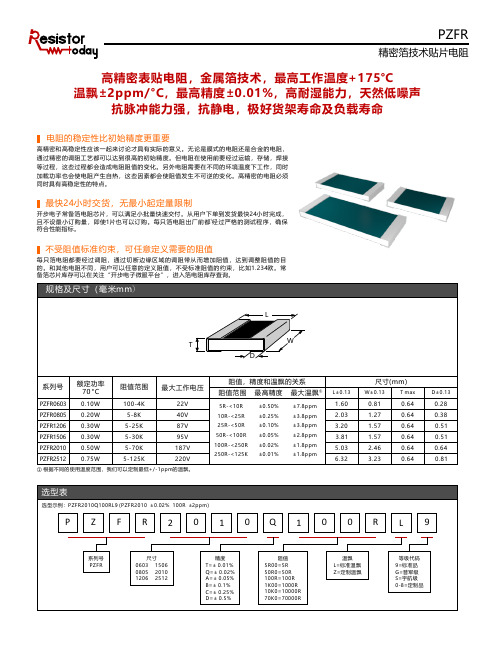
PZFR精密箔技术贴片电阻高精密表贴电阻,金属箔技术,最高工作温度+175°C温飘±2ppm/°C ,最高精度±0.01%,高耐湿能力,天然低噪声抗脉冲能力强,抗静电,极好货架寿命及负载寿命高精密和高稳定性应该一起来讨论才具有实际的意义。
无论是膜式的电阻还是合金的电阻,通过精密的调阻工艺都可以达到很高的初始精度。
但电阻在使用前要经过运输,存储,焊接等过程,这些过程都会造成电阻阻值的变化。
另外电阻需要在不同的环境温度下工作,同时加载功率也会使电阻产生自热,这些因素都会使阻值发生不可逆的变化。
高精密的电阻必须同时具有高稳定性的特点。
电阻的稳定性比初始精度更重要最快24小时交货,无最小起定量限制开步电子常备箔电阻芯片,可以满足小批量快速交付。
从用户下单到发货最快24小时完成,1且不设最小订购量,即使1片也可以订购。
每只箔电阻出厂前都经过严格的测试程序,确保符合性能指标。
不受阻值标准约束,可任意定义需要的阻值每只箔电阻都要经过调阻,通过切断边缘区域的调阻带从而增加阻值,达到调整阻值的目的。
和其他电阻不同,用户可以任意的定义阻值,不受标准阻值的约束,比如1.234欧。
备箔芯片库存可以在关注“开步电子微服平台”,进入箔电阻库存查询。
常① 根据不同的使用温度范围,我们可以定制最低+/-1ppm 的温飘。
PZFR精密箔技术贴片电阻额定功率%环境温度°C1007550250-55°C +70°C-75-50-250+25+50+75+100+125+150+175在需要选择一个具有长期稳定性的电阻的时候,几个因素需要被考虑。
这些因素包括:温度系数(TCR ), 功率系数(PCR ), 负载寿命,寿命末期精度,噪声,热电势,抗静电能力。
PZFR 系列箔电阻基于全新的Z1箔技术生产,Z1箔技术在原有Z 箔技术的基础上改进了绑定层和保护层,极大的改善了电阻的稳定性和耐湿能力,使得该电阻可以在很宽的温度范围内工作。
天二插件金属氧化膜电阻MO系列选型规格书
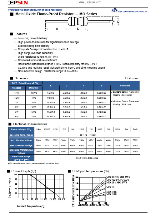
■ Power Graph (℃)
70℃
■ Hot-Spot Temperature (%)
MO 3B 5B/ MO 7WS MO 2WS/ MO 3WS MO 2B / MO 1WS MO 1B MO 1/2B MO 1/4B
SURFACE TEMP. RISE ( )
Rated Load(%)
Ambient Temperature (℃)
★ Miniature Series: Flameproof Coating , Pink color
■ Electrical Characteristics
Power rating at 70℃ 1/4W 1/2WS 1/2W 1WS
Operating Temp. Range
Max. Working Voltage 200V 250V 250V 300V
No deterioration of coatings and markings
Terminal Strength
Direct load for 10 sec. In the direction off the terminal leads. Tensile:≧2.5kg
★ Rated continuous Working Voltage (RCWV) = POWER.RATING.* RESISTANCE.VALUE
H
28±2.0 26±2.0 35±2.0 32±2.0 35±2.0 35±2.0
Unit: mm
d
Comment
0.55±0.03 0.65±0.03 0.76±0.03 0.76±0.03 0.78±0.03 0.78±0.03
★ Standard Series: Flameproof Coating , Grey color
电阻器参数及选型(贴片电阻)
电阻器参数及选型(贴片电阻)电阻器,简称电阻(Resistor,通常用“R”表示),在物理学中表示导体对电流阻碍作用的大小。
导体的电阻越大,表示导体对电流的阻碍作用越大。
不同的导体,电阻一般不同,电阻是导体本身的一种性质。
导体的电阻通常用字母R表示,电阻的单位是欧姆,简称欧,符号为Ω。
计算公式:串联:R=R1+R2+……+Rn。
并联:1/R=1/R1+……+1/Rn。
定义式:R=U/I。
决定式:R= ρ L/S(ρ表示电阻的电阻率,是由其本身性质决定,L表示电阻的长度,S表示电阻的横截面积)电阻是电路元件中应用最广的一种,其性能好坏对电路工作的稳定性有极大影响。
是一个限流元件,它的主要用途是稳定和调节电路中的电流和电压,其次还可作为消耗电能的负载、分流器、分压器、稳压电源中的取样电阻、电路中的偏置电阻。
欧姆定律电阻的参数介绍1.标称阻值:产品上标示的阻值,单位为欧,千欧,兆欧,标称阻值都应符合阻值标准系列所列数值乘以10n倍(n为整数)。
2.允许误差:电阻和电位器实际阻值对于标称阻值的最大允许偏差范围,它表示产品的精度。
3.额定功率:在规定的环境温度和湿度下,假定周围的空气不流通,在长期连续负载而不损坏或基本不改变性能的情况下,电阻器上允许消耗的最大功率,一般选用其额定功率比它在电路中消耗的功率高1-2倍。
额定功率分19个等级,常用的有0.0625W、0.125W、0.25W、0.5W、1W、2W、3W、5W、7W、10W。
4.最高工作电压:电阻在长期工作不发生过热或电击穿损坏时的电压。
如果电压超过规定值,电阻器内部产生火花,引起噪声,甚至损坏。
5.温度系数(TC):表示温度每变化1度时,电阻器阻值的相对变化量;如±100ppm/℃。
0Ω电阻存在的意义零欧姆电阻又称为跨接电阻器,是一种特殊用途的电阻,0欧姆电阻的并非真正的阻值为零,欧姆电阻实际是电阻值很小的电阻(一般为50mΩ),在电路中没有任何功能,只是在PCB上为了调试方便或兼容设计等原因。
台湾天二CRA系列厚膜排阻选型规格书

■ Storage Data:
Storage time at the environment temp: 25±5℃& humidity: 50±20% is valid for one year from the date of delivery.
深圳捷比信--高品质精密元件供应商
www.jepsun.com
Unit: mm
ψD
P 1.25±0.10 1.25±0.10 8.0±0.20 1.75±0.10 3.5±0.05 1.20±0.10 2.20±0.10 8.0±0.20 1.75±0.10 3.5±0.05 1.25±0.10 1.25±0.10 8.0±0.20 1.75±0.10 3.5±0.05 1.20±0.10 2.20±0.10 8.0±0.20 1.75±0.10 3.5±0.05 1.90±0.20 3.50±0.20 8.0±0.20 1.75±0.10 3.5±0.05 2.0±0.05 0.45±0.10 2.0±0.05 0.60±0.10 2.0±0.05 0.45±0.10 1.50 -0 2.0±0.05 0.60±0.10 2.0±0.05 0.75±0.10 4.0±0.1
260±5℃ for 30 seconds. 260±5℃ for 10 seconds. -55℃ to +155℃,5 cycles Preheating temperature:350±10℃ Electric iron preheating time:3+1/-0 sec The tested resistor be immersed into isopropyl alcohol of 20~25℃ for 60 secs. Then the resistor is left in the room for 48 hrs. hrs〝ON〞and 0.5 hr〝OFF〞. 0.5 hr〝OFF〞. Max. Overload voltage for 1 minute.
- 1、下载文档前请自行甄别文档内容的完整性,平台不提供额外的编辑、内容补充、找答案等附加服务。
- 2、"仅部分预览"的文档,不可在线预览部分如存在完整性等问题,可反馈申请退款(可完整预览的文档不适用该条件!)。
- 3、如文档侵犯您的权益,请联系客服反馈,我们会尽快为您处理(人工客服工作时间:9:00-18:30)。
■ Package
Inner Box Size Reel Size H(mm) External Box Size Contain (Kpcs) Length (mm) Width (mm) Height (mm)
1 2 3 5 10
13 24 36 60 113
25K 50K 150K 300K
180 180 430 400
16.0±2.0 178±2.0
深圳捷比信--高品质精密元件供应商
www.jepsun.com
■ Tapping Specification
■ Dimension
Packaging Type A B W E F G H T
Unit: mm
ψD
P
0402 0603 Paper Type 0805 1206 1210
2.0±0.1
4.0±0.1
■ Dimension
Packaging Type A B W E F G H T
Unit: mm
ψD
+0.10
ΨD1
T1
P
Embossed Type
2010 2.80±0.20 5.60±0.20 12±0.10 1.75±0.10 5.5±0.05 4.0±0.10 2.0±0.05 0.23±0.10 1.50 2512 3.40±0.20 6.70±0.20 12±0.10 1.75±0.10 5.5±0.05 4.0±0.10 2.0±0.05 0.23±0.10
4.0±0.10 4.0±0.10 4.0±0.10 4.0±0.10 4.0±0.10
2.0±0.05 0.45±0.10 2.0±0.05 0.60±0.10 2.0±0.05 0.75±0.10 1.50 -0 2.0±0.05 0.75±0.10 2.0±0.05 0.75±0.10
+0.10
1.50±0.10 0.85±0.15 4.0±0.1 1.50±0.10 0.85±0.15
-0
深圳捷比信--高品质精密元件供应商
www.jepsun.com
■ Packing Material Data / Storage Data ■ Front & Back Lead Dimension
■ Top Adhesive Peel Off Strength:10~70g
180 180 200 400
60 110 200 200
■ Storage Data:
Storage time at the environment temp: 25±5℃& humidity: 50±20% is valid for one year from the date of delivery.
● Packaging Information
◆ For All Series
■ Dimension
Unit: mm
TYPE 7” 0402 13” 13” 0603 0805 1206 1210 2010 2512 7” 10” 13” 7” 7”
SIZE
A
ψB 13.5±1.0 13.5±1.0 13.5±1.0 13.5±1.0 13.5±1.0 13.5±1.0 13.5±1.0 13.5±1.0
ψC 21±1.0 21±1.0 21±1.0 21±1.0 21±1.0 21±1.0 21±1.0 21±1.0
ψD 60±1.0
W 11.5±2.0
ψM 178±2.0 330±2.0 330±2.0 178±2.0 254±2.0 330±2.0 178±2.0
10K/Reel 2.0±0.5 40K/Reel 2.0±0.5 50K/Reel 2.0±0.5 5K/Reel 2.0±0.5
Resistance Range
T.C.R. (PPM/℃)
Standard Tolerance (%)
1Ω~47Ω (±600PPM) 48Ω~470Ω (±400PPM) 471Ω~1KΩ ±5%,10% (1%,2% available)
1Ω~1KΩ
<30 sec at 11.25W <30 sec at 15W
±1:±(1.0%+0.05Ω) ±5:±(2.0%+0.1Ω)
IR Reflow
Sony SS-00254
100
±1:±(1.0%+0.05Ω) ±5:±(1.0%+0.05Ω)
Leaching Soldering Heat Temperature Cycling Electric Iron
Sony SS-00254-9 JIS C 5201-1 clause 4.18 JIS C 5201-1 clause 4.19 Sony SS-00254-5 JIS C 5201-1 clause 4.29 JIS C 5201-1 clause 4.24 JIS C 5201-1 clause 4.25 JIS C 5201-1 clause 4.6 JIS C 5201-1 clause 4.33
5 6 7 8
External Electrode (Sn) Resistor Layer (RuO2) Primary Overcoat (Glass) Secondary Overcoat (Epoxy)
■ Features
— The accurate fusibility is applicable to safety circuits in the wide range of electronic sets. — Small in size, light in weight. — Low temperature coefficient.(under ±400 PPM/℃) — Noncombustible insulated coat. — May treat as the general resistance use.
250 200 150 Peak : 250 0 ℃ 230 ℃ or higher 180 ℃ 150 ℃ Pre Heating Zone 90 ± 30 s 30 ± 10 s Soldering Zone 50 Heating Time
5
Refer to Ratings
JIS C 5201-1 clause 4.13
05
5W
Fusing Power 2.5W 3W 3.25W 5W 7.5W 15W
Quantity 01:1000PCS 02:2000PCS 04:4000PCS 05:5000PCS
深圳捷比信--高品质精密元件供应商
www.jepsun.com
■ Appendix For SMD Chip Resistor
(±200PPM)
For non-standard parts, please contact our sales dept. Operating Temperature Range :−55℃~+155℃.
深圳捷比信--高品质精密元件供应商
www.jepsun.com
■ Parts Number Explanation ■ Example:
260±5℃ for 30 seconds. 260±5℃ for 10 seconds. -55℃ to +155℃,5 cycles Preheating temperature:350±10℃ Electric iron preheating time:3+1/-0 sec The tested resistor be immersed into isopropyl alcohol of 20~25℃ for 60 secs. Then the resistor is left in the room for 48 hrs.
FCR
Product Type
1206
Size (Inch) 0402 0603 0805 1206 1210 2010 2512
J
Resistor Tolerance J:±5% F:±1%
10K
Resistors Value
P
Package P、Q:Paper Taping E:Embossed Taping D:Packed in a Bag
0.70±0.10 1.20±0.10 8.0±0.20 1.75±0.10 3.5±0.05 1.05±0.20 1.80±0.20 8.0±0.20 1.75±0.10 3.5±0.05 1.55±0.20 2.30±0.20 8.0±0.20 1.75±0.10 3.5±0.05 1.90±0.20 3.50±0.20 8.0±0.20 1.75±0.10 3.5±0.05 2.85±0.20 3.50±0.20 8.0±0.20 1.75±0.10 3.5±0.05
JIS C 5201-1 clause 4.8
-55℃ ~+155℃, 25℃ is the reference temperature General: 2.5 times RCWV or Max. Overload voltage for 5 seconds. High Power: 5 × Rated power for 5 seconds
深圳捷比信--高品质精密元件供应商
www.jepsun.com
■ Fusible Chip Resistor — FCR Series
■ Construction
1 2 3 4
Alumina Substrate Bottom Electrode (Ag) Top Electrode (Ag/Pd) Barrier Layer (Ni)
100±1.0 11.5±2.0 100±1.0 11.5±2.0 60±1.0 11.5±2.0