AB变频器PowerFlex753调试报告
Powerflex753变频器配IO卡调试参数
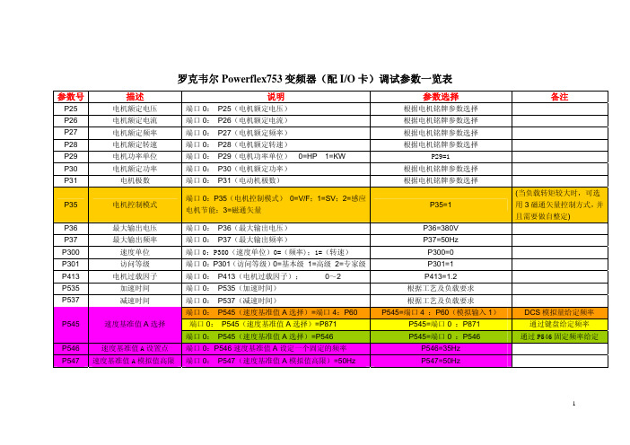
罗克韦尔Powerflex753变频器(配I/O卡)调试参数一览表参数号 描述 说明 参数选择 备注 P25 电机额定电压 端口0: P25(电机额定电压) 根据电机铭牌参数选择P26 电机额定电流 端口0: P26(电机额定电流) 根据电机铭牌参数选择P27 电机额定频率 端口0: P27(电机额定频率) 根据电机铭牌参数选择P28 电机额定转速 端口0: P28(电机额定转速) 根据电机铭牌参数选择P29 电机功率单位 端口0: P29(电机功率单位)0=HP 1=KW P29=1P30 电机额定功率 端口0: P30(电机额定功率) 根据电机铭牌参数选择P31 电机极数 端口0: P31(电动机极数) 根据电机铭牌参数选择P35 电机控制模式 端口0:P35(电机控制模式) 0=V/F;1=SV;2=感应电机节能;3=磁通矢量P35=1(当负载转矩较大时,可选用3磁通矢量控制方式,并且需要做自整定)P36 最大输出电压 端口0: P36(最大输出电压) P36=380VP37 最大输出频率 端口0: P37(最大输出频率) P37=50HzP300 速度单位 端口0:P300(速度单位)0=(频率);1=(转速) P300=0P301 访问等级 端口0:P301(访问等级)0=基本级 1=高级 2=专家级 P301=1P413 电机过载因子 端口0: P413(电机过载因子);0~2P413=1.2P535 加速时间 端口0: P535(加速时间) 根据工艺及负载要求P537 减速时间 端口0: P537(减速时间) 根据工艺及负载要求端口0: P545(速度基准值A选择)=端口4:P60 P545=端口4 :P60(模拟输入1)DCS模拟量给定频率端口0: P545(速度基准值A选择)=P871 P545=端口0 :P871 通过键盘给定频率P545 速度基准值A选择端口0: P545(速度基准值A选择)=P546 P545=端口0 :P546 通过P546固定频率给定 P546 速度基准值A设置点 端口0:P546速度基准值A设定一个固定的频率 P546=35HzP547 速度基准值A模拟值高限 端口0: P547(速度基准值A模拟值高限)=50Hz P547=50Hz参数号 描述 说明 参数选择 备注 P548 速度基准值A模拟值底限 端口0: P548(速度基准值A模拟值低限)=00Hz P548=00HzP308 方向模式 端口0: P308(方向模式)= 0 Unipolar(单极性) P308=0P150 数字输入配置 端口0: P150=0 运行边缘 P150=0P164 DI数字量输入正向运行 端口0: P164(数字输入正向运行)=端口4:P1的B00位=1 ;(数字输入DI0)端口4:P1的B00位=1 ;(数字输入DI0)DI0=正转运行P165 DI数字量输入反向运行 端口0: P165(数字输入反向运行)=端口4:P1的B01位=1 ;(数字输入DI1)端口4:P1的B01位=1 ;(数字输入DI1)DI1=反向运行端口0: P70(自整定)说明:(只有端口0:P35 = 1、2、3时整定有效)P70 自整定端口0:P70(自整定)0=就绪1=计算2=静态调节3=旋转调节 P70=2设定完成后启动变频器,变频器开始整定(电机不会旋转),提示整定完成后停止。
PowerFlex753及SMC150参数设定

17 PF753
23 DEVICE NET 23 DEVICE NET HOST PARAMETERS 23 DEVICE NET HOST PARAMETERS 23 DEVICE NET HOST PARAMETERS 23 DEVICE NET HOST PARAMETERS 23 DEVICE NET HOST PARAMETERS 24 25 20-750-2262C-2R《IO 24V》 26 27 27
故障时斜坡停机,暂不设置 电压 电流 故障代码 扩展IO DI0-DI6输入状态 主板开关量输入状态 变频运行状态输出 变频故障状态输出
X中将变频或软启参数上传
DLS数量
P4
5
DL TO NET 01 P17 0 8
DL TO NET 02 P18 0 7
DL TO NET 03 P19 0 951
DL TO NET 04 P20 5 1
DL TO NET 05 P21 0 220
RO0选择
P10 端口0 ,参数935,位16
RO1选择
P20 端口0 ,参数935,位7
参数表
参数名称
参数号 参数设定值
电机额定电压 P25 根据实际设定
电机额定电流 P26 根据实际设定
电机额定频率 P27 根据实际设定
电机额定转速 P28 根据实际设定
功率单位
P29 根据实际设定
电机额定功率 P30 根据实际设定
电机极对数
P31 根据实际设定
电机控制模式 P35 0-InductionVHZ
基准A倍比 549 默认
基准B倍比 5ห้องสมุดไป่ตู้0 默认
罗克韦尔自动化 - PowerFlex 753 驱动器 (修订版 1.009) 更新说明说明书

Release NotesPowerFlex® 753 Drives (revision 1.009)These release notes correspond to major revision 1, minor revision 9 offirmware for PowerFlex® 753 drives.Introduction The following information is included in this document:Determining Firmware Revision Level This section describes procedures to determine the firmware revision of your PowerFlex 753 drive.Using the Drive LCD HIM1.Access the Status screen, which is displayed on HIM power up. Figure 1 Status ScreenFor information about:See page: Determining Firmware Revision Level1Using the Drive LCD HIM1Using DriveExplorer Lite/Full2Using DriveExecutive3 Firmware Flashing3Installing the Flash Kit4Using DriveExplorer Lite/Full to Flash Update4Using DriveExecutive to Flash Update5Using ControlFLASH to Flash Update7Using HyperTerminal to Flash Update9 Enhancements14 Corrected Anomalies14 Restrictions15 Rockwell Automation Support16Host Drive480V 2.1A20F...D2P12PowerFlex® 753 Drives (revision 1.009)e the or key to scroll to Port 00 for the Host Drive.3.e the or key to scroll to the DIAGNOSTIC folder.5.Device Version .6.FW Revision is listed under –Main Control Board; see Figure 2.Figure 2 Device Version Information ScreenUsing DriveExplorer Lite/FullImportant:You need DriveExplorer version 6.02 or later to interfacewith the PowerFlex 753 drive. To obtain the latest version,visit the Allen-Bradley Web Updates site located at/support/abdrives/webupdate .unch DriveExplorer and go online with the PowerFlex 755 drive. To connect to the drive, use a 1203-USB converter, a 1203-SSS converter, or an EtherNet/IP network connection .2.In the Devices hardware view, select the PowerFlex 753 drive.Once selected, information regarding the PowerFlex 753 drive is shownin the right panel including the current firmware revision number.PowerFlex 753 480V 2.1AProduct Revision 1.007Product Serial Number SN–Main Control BoardFW Revision 1.007PowerFlex® 753 Drives (revision 1.009)3Using DriveExecutiveImportant:You need DriveExecutive version 5.02 or later to interface with the PowerFlex 753 drive. To obtain the latest version, visit the Allen-Bradley Web Updates site located at /support/abdrives/webupdate unch DriveExecutive and go online with the PowerFlex 755 drive. To connect to the drive, use a 1203-USB converter, a 1203-SSS converter, or an EtherNet/IP network connection.2.In the Drives hardware view, select the PowerFlex 753 drive (X in Figure 3on page 3).3.Click the information icon (Y in Figure 3) to display the drive’s Properties dialog box.4.In the Properties dialog box, the “Revision:” field (Z in Figure 3) will show the drive’s current firmware revision number.Figure 3 PowerFlex 753 Drive Information Accessed Through DriveExecutive Firmware Flashing This section describes procedures to flash upgrade your drive firmware.Flash kits for drives are provided on the Allen-Bradley Web Updates site located at /support/abdrives/webupdate .Flashing can be performed using a 1203-USB or 1203-SSS converter. For information on connecting either converter to your drive, refer to the1203-USB USB Converter User Manual, publication DRIVES-UM001 or the 1203-SSS Smart Self-powered Serial Converter User Manual, publication 20COMM-UM001. Z XY4PowerFlex® 753 Drives (revision 1.009)Installing the Flash Kit1.Install the flash kit utility from the Allen-Bradley Web Updates site forthe PowerFlex 753 drive, which includes the latest version of theControlFLASH utility and deploys firmware files for usingHyperTerminal on your computer.2.You are now ready to use DriveExplorer, DriveExecutive,ControlFLASH or HyperTerminal to update the drive. Refer to therespective section and follow the instructions.Using DriveExplorer Lite/Full to Flash Update1.With the Flash Kit installed (see Installing the Flash Kit), launchDriveExplorer and go online (via a 1203-USB or 1203-SSS converter)with the PowerFlex 753 drive.2.In the Drives hardware view, select the PowerFlex 753 drive (X inFigure 3on page3).3.Click the information icon (Y in Figure 3) to display the drive’sProperties dialog box.4.In the Properties dialog box, click the Details tab.5.With the Main Control Board selected, click Flash Update.Important:Flash updating the device firmware may cause the device toload defaults. It is recommended that you save the setting toyour PC before proceeding.PowerFlex® 753 Drives (revision 1.009)5 6.From the list of available updates, select “v1.009.xxx” and click Next >.7.Follow the remaining prompts until the flash update procedurecompletes and displays the new firmware revision.Using DriveExecutive to Flash Update1.With the Flash Kit installed (see Installing the Flash Kit), launchDriveExecutive and go online (via a 1203-USB or 1203-SSS converter) with the PowerFlex 753 drive.2.In the Drives hardware view, select the PowerFlex 753 drive (Y inFigure 3on page3).3.Click the information icon (Z in Figure 3) to display the drive’sProperties dialog box.4.In the Properties dialog box, click the Component Details tab.5.With the PowerFlex 753 drive selected, click Flash Update.6PowerFlex® 753 Drives (revision 1.009)6.From the list of available devices, select the PowerFlex 753 drive andclick Next >.Important:Flash updating the device firmware may cause the device toload defaults. It is recommended that you save the setting toyour PC before proceeding.7.From the list of available updates, select “v1.009.xxx” and click Next >.8.Follow the remaining prompts until the flash update procedurecompletes and displays the new firmware revision.PowerFlex® 753 Drives (revision 1.009)7Using ControlFLASH to Flash Update1.With the Flash Kit installed (see Installing the Flash Kit on page4),launch ControlFLASH by selecting Start > (All) Programs > Flash Programming Tools > ControlFLASH.2.On the ControlFLASH Welcome dialog box, click Next >.3.The Catalog Number dialog box appears. From the list, choose thecommunication device you will use to update the PowerFlex 753 drive.In the figure below, the embedded EtherNet device is selected.Once the appropriate communication device is selected, click Next >.8PowerFlex® 753 Drives (revision 1.009)4.Now that the correct communication device has been selected, you mustselect which device is being updated. With the Select the PowerFlex…dialog box displayed, follow these steps.a.Expand the hardware view for the communication path you are using(X in Figure 4).b.Select the drive icon that represents the PowerFlex 753 drive you areY in Figure 4).c.Click OK (Z in Figure 4).Figure 4 Selecting the Correct Drive to FlashXYZ5.In the Multiple Assemblies Found display box, select“Port x-PowerFlex 753” from the list and click OK .PowerFlex® 753 Drives (revision 1.009)9 6.In the Firmware Revision dialog box, select “v1.009…” from the list ofavailable updates and click Next >.7.Follow the remaining prompts until the flash procedure completes anddisplays the new firmware revision number.Using HyperTerminal to Flash UpdateImportant:The HyperTerminal process takes at least one hour tocomplete.1.With the Flash Kit installed (see Installing the Flash Kit on page4),access and launch HyperTerminal as shown below.10PowerFlex® 753 Drives (revision 1.009)2.A New Connection dialog box appears.a.Enter the connection device name in the Name field or select an iconfrom the library.b.Click OK once you have finished.3.A Connect To dialog box appears,e the “Connect using:” drop-down menu to select the appropriateconnection device.b.Click OK once you have finished.PowerFlex® 753 Drives (revision 1.009)114.A Properties dialog box will appear for the selected connection device.e any of the drop-down menus to change the various port settings.b.Click OK once you have finished.5.After you click OK, you will get a blank screen.Press Enter on your computer keyboard so the following test screen appears.6.From the Main Menu, select the flash upgrade (X in Figure 5onpage12) by pressing the number 3 key on your computer keyboard.7.Additional text appears. From the Flash Upgrade menu, select thePowerFlex 753 drive (Y in Figure 5) by pressing the number 0 key on your computer keyboard.8.Additional text appears. After reading the conditions, select Yes (Z inFigure 5) to proceed by pressing the letter Y key on your computerkeyboard.12PowerFlex® 753 Drives (revision 1.009)Figure 5 HyperTerminal Test Screen DialogueXYZThe terminal program will start displaying the letter “C”. This signals theXMODEM protocol that the download may proceed. You then have oneminute to start the transfer.Important:You have one minute to complete steps 9…14 orHyperTerminal will return to step 5, where you must repeatsteps 5…8.TIP: To cancel the flash update at any time, press CTRL-X .9.Select Transfer > Send File to display the Send File screen.10.Click Browse and navigate toC: > Program Files > ControlFLASH > 0001 > 0086 > 0490PowerFlex® 753 Drives (revision 1.009)13 11.Search through the subfolder until the “PF753_LP_App_v1_009_xxx.dpi”file appears in the Select File to Send list.12.With the file name highlighted, click Open so it appears in the Filenamedata field in the Send File dialog box.13.In the Protocol box, select “Xmodem.”14.Click Send.A dialog box appears and reports the progress of the update. Thisprocess takes at least one hour for HyperTerminal to complete.When it is complete, the message “Flash Complete” appears.15.Press any key to continue.16.Press the Enter key to return to the main menu.14PowerFlex® 753 Drives (revision 1.009)Enhancements There are no enhancements included in this revision.Corrected Anomalies This section describes the anomalies corrected in this revision.Duty Rating Parameter Would Return to Default ValueThe value of parameter 306 [Duty Rating] would return to its default valueof 0=“Normal Duty” after a reset or after power was cycled on the drive.DeviceLogix Corrupted in NVS when a System Task Fault OccurredAn F918-Control Task Overload, F919-System Task Overload or F920-5msec Task Overload fault could cause the drive to write over the NVS wherea DeviceLogix project is stored and corrupt the NVS copy of the project.After a reset or after power was cycled on the drive, the drive would load thecorrupt NVS copy of the project into active memory and the drive wouldexperience an F282 DLX Checksum fault. The project would not run.Fault Restart DisplayWhen executing an automatic restart after a fault, the drive would notcorrectly display the count down to the restart properly. It would correctlydisplay the tens digit, but it would not display the ones digit.The following table illustrates an example.Time Remaining (seconds)1211109876543210 How it should display countdown1211109876543210 How it does display countdown1_1_1_____________________Non Volatile Storage (NVS)Executing the homing function too frequently or changing certain parametervalues too frequently would cause the drive to stop operating (due to anF918-Control Task Overload, F919-System Task Overload or F920-5 msecTask Overload fault). The Human Interface Module (HIM) would display“Port 0 Comm Loss.” Recovery from this condition required cycling poweron the drive. After power was cycled, the drive would report a F101-PwrDnNVS Blank, F103-PwrDn NVS Incomp or F117-PwrDn NVS Chksm fault,and drive parameter values would be set to their default values.This occurred because the drive was attempting to write to NVS too quickly,and requests for NVS writes were over-running the buffer for NVS writes.The drive would attempt to write to NVS when executing the homingfunction. It would also write to NVS when certain parameters in the SpeedRegulator, Inertia Compensation and (Position) Torque Boost parametergroups were modified. Controlling these parameters via datalink could createa situation where attempts to write to NVS would occur too frequently.PowerFlex® 753 Drives (revision 1.009)15Option Card Version DisplayDisplay of firmware version for option modules on the Human InterfaceModule (HIM) or in configuration software (DriveExplorer, DriveExecutiveor RSLogix 5000) would be incorrect.Port Loss Due to Lost Client Server MessageUnder certain conditions, a certain combination of DPI messages wouldlock up a DPI port.Position Feedback ErrorWhen using position control, the value of parameter 857 [Psn Fdbk] couldbe in error from the actual machine position by one encoder count. Thiscould cause a final position error in your system.Start Inhibit Bit Remained SetParameter 933 [Start Inhibits]/bit 5 “Database” remained set after a HIMCopyCat download. This prevented the drive from starting until power wascycled or the drive was reset.Restrictions There are no restrictions for this firmware revision.Publication 750-RN009A-EN-E – December, 2010Copyright © 2010 Rockwell Automation, Inc. All rights reserved. Printed in USA.U.S.Allen-BradleyDrivesTechnicalSupport-Tel:(1)262.512.8176,Fax:(1)262.512.2222,Email:*****************,Online:/support/abdrives Corporate HeadquartersRockwell Automation, 777 East Wisconsin Avenue, Suite 1400, Milwaukee, WI, 53202-5302 USA, Tel: (1) 414.212.5200, Fax: (1) 414.212.5201Headquarters for Allen-Bradley Products, Rockwell Software Products and Global Manufacturing SolutionsAmericas: Rockwell Automation, 1201 South Second Street, Milwaukee, WI 53204-2496 USA, Tel: (1) 414.382.2000, Fax: (1) 414.382.4444Europe/Middle East/Africa: Rockwell Automation SA/NV, Vorstlaan/Boulevard du Souverain 36, 1170 Brussels, Belgium, Tel: (32) 2 663 0600, Fax: (32) 2 663 0640Asia Pacific: Rockwell Automation, 27/F Citicorp Centre, 18 Whitfield Road, Causeway Bay, Hong Kong, Tel: (852) 2887 4788, Fax: (852) 2508 1846Headquarters for Dodge and Reliance Electric ProductsAmericas: Rockwell Automation, 6040 Ponders Court, Greenville, SC 29615-4617 USA, Tel: (1) 864.297.4800, Fax: (1) 864.281.2433Europe/Middle East/Africa: Rockwell Automation, Brühlstraße 22, D-74834 Elztal-Dallau, Germany, Tel: (49) 6261 9410, Fax: (49) 6261 17741Asia Pacific: Rockwell Automation, 55 Newton Road, #11-01/02 Revenue House, Singapore 307987, Tel: (65) 6356-9077, Fax: (65) 6356-9011Rockwell AutomationSupport To assist you, Rockwell Automation provides technical information on the web. At /support , you can find technicalmanuals, a knowledge base of Frequently Asked Questions (FAQs),technical and application notes, sample code and links to software servicepacks, and a MySupport feature you can customize to best use these tools.If you experience a problem, please review the product documentation. Forfurther help, contact a Customer Support representative:TechConnect Support programs are available for an additional level oftechnical phone support for installation, configuration, and troubleshooting.For more information, contact your local distributor or Rockwell Automationrepresentative, or visit /support . United States(1) 262.512.8176 • Monday – Friday, 7am – 6pm CST Outside United States Please contact your local Rockwell Automation representative for anytechnical support issues.。
AB753变频器参数设置

AB753变频器参数设置1.基本参数设置:首先,我们需要设置变频器的基本参数。
这些参数包括输入电压、输出电压、电流等。
用户需要根据实际情况输入正确的数值。
同时,还需要设置变频器的频率范围,即变频器工作时允许的频率范围,用户可以根据具体的应用需求设置相应的范围。
2.过载保护参数设置:为保护电机和变频器,我们需要设置合适的过载保护参数。
这些参数包括过载保护系数、过载保护时间等。
过载保护系数是指当电机输出扭矩超过额定扭矩的倍数时,变频器会进行保护。
过载保护时间是指当电机输出扭矩超过额定扭矩的时间超过设定值时,变频器将进行保护。
3.PID参数设置:PID控制是一种常用的控制方式,可以用于控制电机的速度、位置等。
在设置PID参数时,需要设置比例系数、积分时间、微分时间等参数。
比例系数是用来调整控制的平稳度,积分时间是用来调整控制的反应速度,微分时间是用来调整控制的稳定性。
需要根据实际情况进行调整。
4.加速、减速参数设置:加速和减速是电机的重要工作状态,需要设置合适的加速、减速参数。
加速时间是指电机从静止状态加速到额定转速所需的时间,减速时间是指电机从额定转速减速到静止状态所需的时间。
合适的加速、减速参数可以提高电机的工作效率和稳定性。
5.输入输出信号设置:变频器支持不同的输入输出信号,用户可以根据实际需求进行设置。
需要注意的是,不同的输入输出信号对应不同的功能,用户需要准确设置各个信号对应的功能。
6.故障保护参数设置:在变频器的使用过程中,可能会出现各种故障。
为了保护电机和变频器,我们需要设置相应的故障保护参数。
这些参数包括过载故障保护、过压故障保护、欠压故障保护等。
用户需要根据实际情况进行设置,以保障设备的安全运行。
7.通信参数设置:总结:AB753变频器参数设置包括基本参数设置、过载保护参数设置、PID 参数设置、加速、减速参数设置、输入输出信号设置、故障保护参数设置和通信参数设置。
用户需要根据实际应用需求和设备特性进行适当调整。
AB-PowerFlex753变频器调试步骤

修改为10%,按Enter键确认
变频器面板显示
“Edit S Curve decel
0.00%”
修改为10%,按Enter键确认
以上设置完成后,选择”I/O”,按Enter键确认
变频器面板显示
“Make a selection:
Start Stop & Dir
…..
…..”
选择”Start Stop & Dir”,按Enter键确认
“Motor Control”设置完成后,选择“Motor Data”,按“Enter”确认
变频器面板显示
“Edit Motor NP Volts”
“400 VAC”
按”Enter”确认
变频器面板显示
“Select type of power units shown on motor nameplate
变频器面板显示
“This section defines Start Stop and Direction digital input functions. Press Enter”
按Enter键确认
变频器面板显示
“Will a digital input be used as a START source?
变频器面板显示
“Edit Min Fwd Speed
1.0Hz”按Enter键确认
变频器面板显示
“Edit Min Rev Speed
1.0Hz”按Enter键确认
“Limits”设置完成后,选择”Tests”,按Enter键确认
变频器面板显示
“Complete these steps in order
面板提示
AB753变频器参数设置

AB753变频器参数设置1.输出频率限制:在变频器的参数设置中,输出频率限制是一个重要参数。
通过设置输出频率限制,可以限制电机的最大输出频率,从而保护电机和其他相关设备。
一般情况下,输出频率限制应根据电机的额定频率来设置,确保在电机的额定工作范围内。
2.输入电压限制:输入电压限制是指变频器的输入电压范围。
根据工厂或现场的电源情况,需要设置合适的输入电压限制参数,以确保变频器可以正常工作和运行。
3.加速时间和减速时间:加速时间和减速时间是指电机从停止状态加速到稳定运行状态所需的时间。
设置合适的加速时间和减速时间参数可以确保电机平稳启动和停止,避免电机过快或过慢的启停过程对设备带来的影响。
4.输出电流限制:输出电流限制是指变频器输出电流的最大限制。
通过设置输出电流限制,可以保护电机免受过载和短路等故障的损害,并提供最佳的运行效果。
5.PID调节:PID调节是一种常用的电机调速控制策略。
通过设置PID调节参数,可以实现电机转速的闭环控制,从而提高电机调速的精确性和稳定性。
6.过流保护和过载保护:过流保护和过载保护是为了保护电机和相关设备免受过电流和过载等故障的损害。
通过设置合适的过流保护和过载保护参数,可以及时检测和响应故障,并采取相应的保护措施。
7.通信参数设置:AB753变频器通常具有与其他设备和控制系统进行通信的能力。
通过设置通信参数,可以实现变频器与其他设备的数据传输和控制,从而实现更高级别的自动化控制。
8.故障报警和保护设置:故障报警和保护设置是为了保护电机和变频器免受各种故障和意外情况的损害。
通过设置合适的故障报警和保护参数,可以及时检测故障并采取相应的保护措施,保证设备的安全性和可靠性。
总结起来,AB753变频器参数设置涉及到输出频率限制、输入电压限制、加速时间和减速时间、输出电流限制、PID调节、过流保护和过载保护、通信参数设置以及故障报警和保护设置等方面。
通过合理设置这些参数,可以确保电机的安全运行和最佳性能,提高生产效率和质量。
AB-PF755调试流程
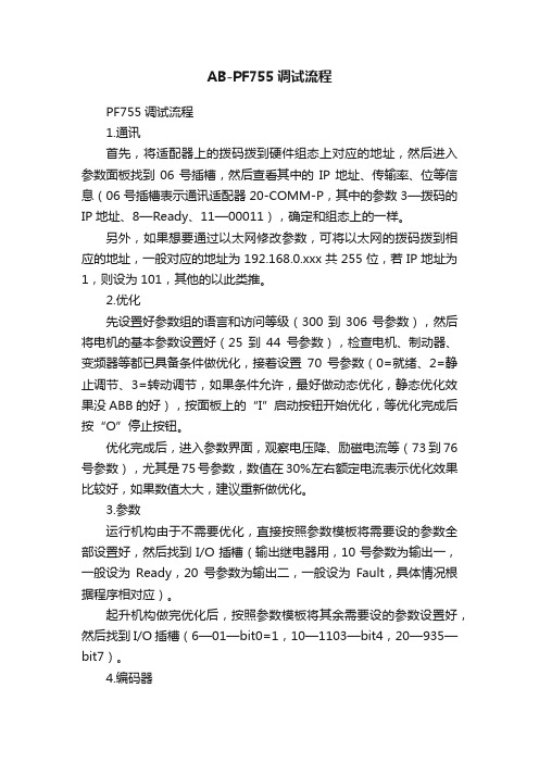
AB-PF755调试流程PF755调试流程1.通讯首先,将适配器上的拨码拨到硬件组态上对应的地址,然后进入参数面板找到06号插槽,然后查看其中的IP地址、传输率、位等信息(06号插槽表示通讯适配器20-COMM-P,其中的参数3—拨码的IP地址、8—Ready、11—00011),确定和组态上的一样。
另外,如果想要通过以太网修改参数,可将以太网的拨码拨到相应的地址,一般对应的地址为192.168.0.xxx共255位,若IP地址为1,则设为101,其他的以此类推。
2.优化先设置好参数组的语言和访问等级(300到306号参数),然后将电机的基本参数设置好(25到44号参数),检查电机、制动器、变频器等都已具备条件做优化,接着设置70号参数(0=就绪、2=静止调节、3=转动调节,如果条件允许,最好做动态优化,静态优化效果没ABB的好),按面板上的“I”启动按钮开始优化,等优化完成后按“O”停止按钮。
优化完成后,进入参数界面,观察电压降、励磁电流等(73到76号参数),尤其是75号参数,数值在30%左右额定电流表示优化效果比较好,如果数值太大,建议重新做优化。
3.参数运行机构由于不需要优化,直接按照参数模板将需要设的参数全部设置好,然后找到I/O插槽(输出继电器用,10号参数为输出一,一般设为Ready,20号参数为输出二,一般设为Fault,具体情况根据程序相对应)。
起升机构做完优化后,按照参数模板将其余需要设的参数设置好,然后找到I/O插槽(6—01—bit0=1,10—1103—bit4,20—935—bit7)。
4.编码器编码器的参数设置如下:不带带125—PF755 125—Encoder 135—PF755 135—Encoder 136—PF755 136—Encoder 40—bit3=1 40—bit3=0 1100—bit0,1,5=1 1100—bit0=1。
AB PF753变频器向导调试步骤

18.设定最小正转频率
19.设定最小反转频率
20.选择测试,点“ENTER”继续
21.选择旋转方向测试,点“ENTER”继续
22.按启动键,开始测试电机旋转方向
23.回答电机旋转方向是否正确
24.如果编码器方向接反,会提示旋转方向不符合,点“ENTER”继续
25.如果编码器方向接反,无需更改编码器接线,选择自动改变,点“ENTER” 继续
34.选择单极性
35.选择速度源
36.选择停车模式:斜坡停止(默认值)
37.母线调节模式:使用默认值
38.设定加速时间
39.设定减速时间
40. 选择S曲线
41.选择完成,点“ENTER”退出即完成。
42.选择退出起动设置,向导设置已完成
5.若无编码器,选择无传感器的速度控制,点“ENTER”继续
6.电机类型选择电磁感应电机,点“ENTER”继续
7.控制模式选择速度控制,点“ENTER”继续
8.选择电机数据,点“ENTER”继续
9.设定电机铭牌数据,额定电压,额定功率,额定电流,额定频率,额定转速, 电机过载系数(默认值),电机极数(自动计算),设定速度单位(默认值)
26.按停止按钮停止电机
27.停止后,会再次提示要求起动电机,如出现测试成功Байду номын сангаас示,停止电机即可
28.选择自动整定,点“ENTER”继续
29.点“ENTER”继续
30.选择旋转整定,点“ENTER”继续
31.起动电机,等待整定结束后,选择退出起动设置
32.选择完成,点“ENTER”继续
33.选择给定、斜坡、停止
10.选择反馈,点“ENTER”继续
11.设定编码器分辨率,点“ENTER”继续
- 1、下载文档前请自行甄别文档内容的完整性,平台不提供额外的编辑、内容补充、找答案等附加服务。
- 2、"仅部分预览"的文档,不可在线预览部分如存在完整性等问题,可反馈申请退款(可完整预览的文档不适用该条件!)。
- 3、如文档侵犯您的权益,请联系客服反馈,我们会尽快为您处理(人工客服工作时间:9:00-18:30)。
AB变频器PowerFlex 753调试报告一、上电初始化,恢复出厂设置可以用面板来操作,面板操作方法请参照面板的操作说明来进行。
具体操作:按下键——>使用或键——>MEMORY——>SER Defaults ——>主机和端口——>回车二、设置PF753变频器基本参数(电机铭牌)具体操作:——>端口——>PowerFlex 753——>线性列表P25=电机铭牌电压P26=电机铭牌电流P27=电机铭牌频率P28=电机铭牌转速P29=电机铭牌功率单位(KW)P30=电机铭牌功率P31=电机极数P300=1(速度单位RPM)P301=2(Expert专家级)三、调试软件安装及使用可以用软件DriverTools或者CCW或者HMI面板来进行:(1)DriverTools软件安装第一步:先找软件安装光盘5.02-DriveTools_SP-A-CD;第二步:在安装光盘里,先找到RSLinx2.54软件安装完,接着继续安装DriverTools5.02.99;第三步:由于5.02.99这个版本里没有本工程要用的20-750-PBUS软件插件,所以我又在网上找到了一个5.05.09版本的升级包,安装完毕。
(2)CCW软件安装第一步:先找软件安装光盘光盘8.00.00-CCW-ZH-Std-DVD第二部:安装(3)HMI面板人机界面(HIM)的使用HIM 显示分为三个区域:1 )状态栏2)数据区域3 )功能键标签对应功能状态栏提供关于主机变频器的运行状况信息。
功能键:最多可使用五个功能键 ( 如图阴影所示)。
功能键将基于 HIM 画面或数据输入模式更改其功能/ 名称。
当功能键激活时,它当前的功能将显示在 LCD 画面中相应的功能键标签上 (HIM 显示区条目 3)。
任意参数的设置:直接访问参数A.按ESC 进入状态屏幕。
B.使用或键浏览要修改名称的设备端口(例如:Port 00为变频器主机)。
C. 按下PAR#软按键显示Jump to Param #(跳转到Param #)输入对话框。
D.使用数字键输入所需的参数号,或使用和软按键,浏览所需的参数号。
为了熟悉此功能,使用上述两种方法浏览220、300、305、535 和871 号参数。
E. 按下ENTER 软按键显示参数。
F.按下EDIT 软按键显示弹出的参数编辑对话框。
下面是关于参数的弹出的对话框屏幕的举例。
提示:EDIT 软按键只对可写参数有效。
使用数字键、小数点软按键和软按键来编辑参数。
按照下面设置参数值:参数300 – [Speed Units(速度单位)设置为HZ参数301 – [Access Level(访问等级)] 设置为2(专家级)参数535 – [Accel Time 1(加速时间1)]设置为50◆导航和数字键:下图显示的五个蓝色多功能键用于滚动菜单/ 画面,执行数据区域 (HIM 显示区条目2) 中显示的相应功能或输入数字值。
五个灰色数字键 (0、1、3、7 和 9) 仅用于输入它们所对应的数字值。
◆单功能键下图所示四个单功能键中的任何一个都始终只能执行它所特定的功能◆变频状态指示灯含义◆恢复工厂初始值对于一台新的变频,在设置参数前需要恢复出厂设置值,防止有个别参数被无意识改变。
如何恢复工厂初始值1. 按下键查看的所在文件夹。
2. 使用或键滚动至Port口选择,使用或键选择主机变频器的端口 00。
3. 使用或键滚动到 MEMORY 文件夹4. 使用或键选择 Set Defaults ( 设置缺省值)。
5. 按下 (回车) 键显示设置缺省值弹出对话框。
恢复工厂设置值有三个选项:Host and ports to default 恢复所有的卡槽和主机参数到工厂初始值This port only to default(most) 恢复本卡槽参数到工厂初始值(大部分参数)This port only to default(all) 恢复本卡槽参数到工厂初始值(全部参数)选择This port only to default(most)恢复不受影响的参数:参数保存和下载1. 按下键查看的所在文件夹。
2. 使用或键滚动至MEMORY 文件夹3. 使用或键选择HIM CopyCat,按键 (回车)4. 使用或键选择CopyCat from Drive to HIM(变频参数)或Upload All Ports(所有端口参数),按键 (回车)5. 选择存储文件(或新建文件);按键 (回车)。
必须有一个存储文件后,才会出现对文件进行删除,改名等选择6. 参数下载先参考步骤1-4,选择CopyCat from HIM to Drive就可从手操器下载参数到变频器(4)DriverTools软件使用打开DriverTools,出现如下图1对话框,点击OK进入到软件状态,如图2:图1图2点击File->New Device,出现如图3对话框,选择变频器类型,本项目为753,点击下一步,出现如图4对话框,选择相应的FW版本号、相应型号变频器等参数,点击下一步,出现如图5的界面图3图4图5图5,鼠标移到Undefined Node,然后右击,出现图6对话框,左击Add Peripheral (也可以点菜单Peripheral->Add),出来选择板卡插入的位置槽,比如面板默认为2槽,如图7,我选择2然后左击OK按钮,出现对话框图8,选择相应的面板型号,本工程用1203-USB,然后根据实际变频器其他附加板卡的配置(比如本工程HIM面板在1槽,Profibus通讯在5槽,编码器卡在6槽,可以参照本文的5、PowerFlex 753与DP通讯参数),配置完毕后填写板卡相应的参数,把调试电缆插上,就可以调试了!图6图7图8DrIverTools打开以后,点击在线的时候,需要通过RS的设置才能再连接,本项目通过USB-1203的电缆连接,先添加Available Driver Types,在下拉菜单找到RS-232 DF1 devices 如图9,选中它,然后点右边的Configure,如下图10设置,设置完点确定,然后选中刚才设置的条目,点击右边的Startup,在Status列会显示Running,如图11:图9图10图11四、单机调试打开软件打开DriverTool,按照3的软件操作方法,然后点击调试向导如图12,按照步骤一步一步选择参数,做优化计算等等图12单机测试的时候,速度参考可以选择默认即P545=P546,从P546设定点来给定速度!单机性能测试完毕之后,PLC联调之后再重新把速度参考选择PLC给定即P545=P875(profibus 网为速度源)。
通用参数设置:P36=380v(最大输出电压)P37=130Hz(最大输出频率)根据工艺及负载要求看哪些需要弱磁的P125= 137(开环反馈) 默认值P227=3P230=22700(抱闸,炉辊时无抱闸)P240=22701(风机)P245=10.0Secs(风机延时10秒关断)P308=1(双极性)P413=1.2(电机过载因子)P520=1480rpm(最大正向速度rmp)根据工艺及负载要求P521=-1480rpm(最大反向速度rmp)根据工艺及负载要求P535=10s(加速时间s)单机测试时走自己的时间,全线自动时从PLC控制,修改为5 sP537=10s(减速时间s)单机测试时走自己的时间,全线自动时从PLC控制,修改为5 sP70= (自整定)(说明:只有端口0:P35=1、2、3时整定有效)0=就绪1=计算2=静态调节3=旋转调节,现做静态测试,再做动态旋转测试=2设定完成后启动变频器,变频器开始整定(电机不会旋转),提示整定完成后停止。
自整定完成。
=3设定完成后启动变频器,变频器开始整定(电机旋转),提示整定完成后停止。
自整定完成。
罗克韦尔Powerflex753 变频器调试参数一览表五、PowerFlex 753与DP通讯参数变频器板卡配置:PORT1端口插入HIM面板,型号为:20-HIM-A6PORT2端口插入通讯电缆,型号为:1203-USBPORT5端口插入Profibus通讯板型号为:20-750-PBUSPORT6端口插入单通道增量型编码器型号为:20-750-ENC-1安装软件:CCW(Connected Components Workbench Standard Edition)具体操作:——>端口——>PowerFlex 753——>线性列表(1)P545=875(PORT5端口插入Profibus通讯板型号为:20-750-PBUS,速度基准值参数设置为:875)(2)其他参数通过通讯卡host parameters(主机参数)datalink1~16来配置,P1~P16对应DL From NET 1~16(下行数据,即为变频器接收数据),P17~P32对应DL To NET 1~16(上行数据,即为变频器发送数据)如下表:六、按照工艺要求,线上辊的控制方式分为纯速度控制、主从控制、张力控制。
联机时需要交给PLC控制权,以下参数需要更改:P35=3P125=60004(速度反馈为Port6:P4编码器反馈)P545=875(端口5为速度主给定)(1)纯速度控制(速度辊,负荷平衡主从控制主辊)P309=5(速度+转矩模式)附加转矩给定(P676)(摩擦补偿、惯量补偿等)(PLC控制)(2)主从控制(负荷平衡主从控制主辊)P309=5(速度+转矩模式)附加转矩给定(P676)来自主辊的速度PI调节器的积分分量输出(PLC控制)这时候需要禁止从辊的积分输出,通过调节参数P635的bit3置位1来禁止(PLC控制)(3)张力控制(张力辊、活套、开卷取机)P309=5(速度+转矩模式)附加转矩给定(P676)包括摩擦补偿、惯量补偿等(PLC控制)这时候需要给定转矩限幅P655(4)炉辊控制(测试炉辊停电切换到备用供电手动点动控制的参数设置)检查P309=5(速度+转矩模式)P166=22001(正向点动)P169=22002(反向点动)P556=170RPM(正向点动速度)P557=-170RPM(反向点动速度)P326= 16479(去掉端口5的勾,手动命令) 此功能需要测试研究七、测试速度通道的“速度调节器积分器输出”步骤:(1)上电初始化,观察“速度调节器积分器输出”(参数P654以下简称:P654)是否为0?测试结果:P654=0.00%(2)变频器上电,拧动编码器(如果编码器已装在电机上,可以轻轻拨动电机轴,这时反馈P3应该有数值),观察P654数值是否有变化?观察“转矩电流反馈”(参数P5,以下简称:P5)变化?测试结果:P3=有反馈数据,P5=0Amps, P654=0.00%(3)启动变频器,给定速度设置为0,观察P654数值变化?给定速度设置不为0,再观察P654数值变化?测试结果:A、给定速度设置为0:P654=0.00%;B、给定速度设置不为0:1)编码器没有固定在轴时,n=-3Hz,P654=-85.02%,P5=-8.3Amps(编码器手动反馈)2)编码器软连接到轴上时,n=2Hz,P654=2.91%(不稳定)n=-2Hz,P654=-1.91%(不稳定)n=5Hz,P654=4.87 %(不稳定)(4)停止变频器,观察P654是否为0?测试结果:P654=0.00%(5)初始给定“速度调节器转矩重置”参数P652(即为预设值参数,以下简称:P652)=5%,观察P654数值变化?测试结果:P652=5%时,P654=5.00%(6)继续(5)步骤,启动变频器,观察P5和P654数值变化?停止变频器,观察P5和P654数值变化?测试结果:A、P652=5%, P647=50/sec,1)启动变频器给定速度n=-5Hz,P5=-8.30 Amps, P654=-83.5%2)停止变频器P5=,P654=5.00%B、P652=5%, P647=100000/sec,1)启动变频器给定速度n=-5Hz,P5=-8.30Amps, P654=-83.03%2)停止变频器P5=0, P654=5.00%八、测试摩擦补偿方法(1)静态补偿测试附表1(2)动态补偿测试附表2。