POP-D型文本显示器使用手册V1.0
DP 系列大屏显示器 说明书

P
Q
48H 49H 4AH \ 4CH ADH 4EH 4FH 50H \
\
\
8
功能及相应参数说明
显示内容 R
S
T
U
VWK
Y
Z
ASCⅡ码 52H \ 54H 55H \ 57H \ 59H 5AH
显示
\
\
\
回答 大屏收到计算机的命令后,核对地址和格式
地址不相符时:不回答
格式不相符时:回答 !AAErr↙ AA 为大屏实际地址
概述
1、概述
DP 系列大屏显示器分为测量输入型、通讯接口型和时钟型三类,以满足不同的应用要求。 1 台大屏机箱内可以混装这三种类型,完成较复杂的功能。
采用高亮度 LED 显示器件,锁存显示方式。亮度高,均匀,抗干扰能力强 大屏内各部件采用完全组合式结构,标准化程度高,生产周期短,维修方便 LED 字高从 45.72mm(1.8 英寸)到 304.8mm(12 英寸) 测量输入型可输入热电阻、热电偶、电流、电压等模拟信号和脉冲信号,单通道或多通 道。功能详见 KS 系列各类仪表 通讯接口型用于与计算机、KS 系列仪表或其它智能设备配合使用 时钟型用于年、月、日、时、分、秒的显示
101.6(4.0),127(5.0),177.8(7.0),203.2(8.0),254.0(10.0),304.8(12.0)
3:LED 位数
4:指示灯数量,不需要指示灯时为 0
5:继电器输出(限通讯协议类型 C) T0:无继电器输出 T1 ~ T4:1 ~ 4 点输出 6:通讯接口 232:表示 RS-232 接口 485:表示 RS-485 接口
101.6(4.0),127(5.0),177.8(7.0),203.2(8.0),254.0(10.0),304.8(12.0)
SAMPO 多媒体电浆显示器 说明书
歡迎使用SAMPO多媒體顯示器為能正確的操作使用,請仔細閱讀這本使用說明書●請妥善保管使用說明書及保證書,萬一使用中產生疑問或發生問題時,它也許能給您提供一些幫助。
●生產機號在品質管理上是很重要的,請確認顯示器上的生產機號與保證書上的生產機號是否一致。
Array免責聲明1.聲寶股份有限公司及著作人不對於此手冊的相關內容、適銷性或適合於某特定目的保證或擔保。
2.本公司保有修訂本出版品的權利,內容如有變更,恕不另行通知安全說明請詳讀及妥善保存此說明手冊,並依照產品本身所示之說明操作本產品。
使用本產品前,請注意下列指示:●安裝1.請將顯示器放置在平穩的桌上,若採壁掛方式請確定牆壁與結合體皆安全穩固。
2.將顯示器壁掛嵌入於室內裝潢時,應與牆壁保留10公分以上的散熱空間。
3.請勿將顯示器安裝於密閉或通風不良的廚架中。
4.請勿將本產品置於高溫,潮濕或多灰塵以及陽光可直接照射的地方;例如室外廣場、浴室、廚房、游泳池等場所。
5.本產品為家用產品,不適合安裝於車內、飛機及船艙使用。
6.建議您不要在喇叭或大型金屬旁操作本產品,以免受磁性干擾,影響本產品的畫質及色彩。
●清潔1.清潔機器時請將電源線拔掉,面板請使用乾淨軟布擦拭,勿用噴霧式清潔劑或有機溶劑擦擦拭,以免破壞面板表面2.請勿讓任何液體滲入機體內部,以免機器發生故障。
3.外殼擦拭必須使用軟布拭,不可使用揮發油,香蕉水等化學液體擦拭,以免塑膠外殼變質或塗料脫落。
●使用1.長時間不使用本產品時,請將電源線拔掉。
2.電源啟用時,請勿將插頭拔下。
3.搬運或移動本產品時務必拔下電源插頭,並需二人以上協力以確保安全。
4.顯示器從溫度較低的環境突然搬入較溫暖的環境時會產生結露,此時不可立即開機使用,請將電源關閉並放置一段時間後再行使用。
5.請勿長時間顯示靜止畫面,因為這會導致影像殘留。
●維修服務發生以下情形時請立即拔掉電源,並通知服務人員檢修。
┌電源線或電源插頭損壞。
├物品掉落機器內或有液體傾倒入機器內;機器置於水中或雨中。
FURUNO MFDBB多功能显示器操作手册说明书

PUB. NO. OME-44461-D(1009, DAMI) MFDBBThe purpose of this guide is to provide the basic operation for this equipment. For more detailed information, see the Operator's manual.All brand and product names are trademarks, registered trademarks or service marks of their respective holders.Table of ContentsOperating Controls........................................................................................................2How to Use the Controls...............................................................................................3Using the SD Cards ......................................................................................................4General .........................................................................................................................5Chart Plotter..................................................................................................................7Radar ..........................................................................................................................13AIS ..............................................................................................................................17Fish Finder (19)3D aerial view display2D displayFor RotoKey operation, see POINTS ROUTEEntering a pointMomentary pushRadarFish finderSwitching active displayACTIVEACTIVEMenu operationPT-0001MOB markSaving point at current positionPointMOBOwn shipKeysple , has a line separating the two functions. Access the top function with a momentary RotoKey and soft controls•Access by rotating or pushing.•They change depending on mode or function in use.•Long pushto show full set of soft controls for current mode.The cursorThe cursor mainly functions to•measure the range and bearing to a location on the radar and chart plotter •select position for a point and point routeIt takes on one of two configurations depending on its state.Soft controls (radar)Inserting an SD card1.Pull the tab on the card drive lid to open the card drive.2.Insert the SD card in either card drive as shown right, with the label up. It should go in easily. If it is doesn’t, do not try to force it.3.Push the card until it is in place and then close the lid.Removing an SD card1.Pull the tab on the card drive lid to open the card drive.2.Push in the card until it pops out.3.Remove the card with your fingers and then close the lid.Selecting a range•Press RANGE OUT to increase the range.•Press RANGE IN to decrease the range.Scrolling the chart, radar picturePress arrow or diagonal to scroll chart, radar picture.Returning own ship icon to screen centerThe own ship icon marks your vessel’s position. If you can’t find it on the chart, or you wish to re-center it on the radar or chart plotter, push the SHIP/3D button to return it to the screen center.Chart, radar picture orientationChart, radar picture orientation is available in Head-up, North-up and Course-up.Head-up: Chart with current compass heading upward.North-up: Orientation fixed with true north upward.Course-up: Destination is always at the screen top.Head UpCourse UpNorth UpNorth UpCourse UpSelecting a displayPresetting the display selection screen2D12Select display.Confirm.Chart plotter displayCartographic featuresFinding information about a cartographic objectCursor*(red)Point(black circle in red square)Boat icon (red)DPT m103SOG kt9.2COG °T 23.2SOG/COG predictor (red)+PT-0015Route(blue: inactive red: active)Direction of turn indicator (red)Heading line (green)* Inactive c u rsor. Active c u rsor looks like this .Hiding/Showing cartographic features, text information CustomArea of Shallow DepthRestoring default cartographic featuresShowing tidal current and tide informationHow to use pointsA point marks a geographical position on the chart plotter. You can mark points at the cursor po-sition, ship’s position, or at a specified location. Points are marked on the screen with the way-) and waypoint numbers. Points are stored in the points list, where you can Placing a point(tide graph)Tide graphon chart plotterPT 0001Going to a pointRoutesA route consists of a series of points leading to ultimate destination. Routes are stored in the Routes list, where you can edit or delete routes as necessary.Creating a routePT 0001Point set asPoint set asdestinationFollowing a routeFlyoverRadar displayMeasuring distance to a targetData boxesV RM box (hidden w hen no V RM is active)CursorVRM1EBL1VRM2EBL2Bearing scaleHeading lineOwn ship iconNorth markerGuard zone+VRM2VRM1TargetV RM box Check V RM box for range.SelectappropriateV RM.Set V RM on inner edge of target. Confirm selection.V RM 1 2.434 nmV RM 2 6.308 nmSelect V RM.Confirm selection.Measuring bearing to a targetSetting a guard zoneA guard zone alerts you with audio and visual indications when a target enters the alarm zone.Check EBL b ox for b earing.EBL1EBL2EBL b oxTar g et+EBL 1 210.2 °TEBL 2 59.4 °TGuard Zone153C U R SUsing ARPAThe Automatic Radar Plotting Aid (ARPA) is a radar function for target tracking and collision avoidance. ARPA tracks and provides detailed information for up to 30 targets. You can track targets automatically, manually or a combination of both.Manually acquiring a targetARPA target symbolsShowing target dataCPA/TCPA alarmThe CPA/TCPA alarm alerts you (with audio and visual alarms) when a tracked target violates the selected limits.Targets menu operationSet CPA and TCPAalarm values withRotoKey; rotate toselect value, pushto confirm.Exit MenuTIP!Sho w ing/hiding track historyEnabling, disabling AISAIS target symbolsTargets menu operation Green, O N, Gray, OFFAIS proximity alarmThe AIS proximity alarm alerts you (with audio and visual alarms) when an AIS targets comes within a specific distance.Showing AIS target dataFish finder displaySelecting automatic or manual operationYour fish finder can be operated automatically or manually. In automatic operation, range, gain and clutter are automatically adjusted.* Requires water temperature sensor.**ACCU-FISH feature estimates length of individual fish.(Requires appropriate transducer and Bottom Discrimination Sounder BBDS1, Network Sounder DFF1 or DFF3, or Color LCD Sounder FCV-1150.)34Select Auto soft control.Choose Fishing or Cruising for Auto; Off for Manual.FishingCruising OffConfirm selection.Manual operationSelecting operating frequencyLow frequency: Use for general detection and judging bottom conditions.High frequency: Use for detailed observation.Dual: Both high and low frequencies.Appearance of cl u tterHFLF DualZoom displayACCU-FISHACCU-FISH measures the depth and length of individual fish, showing measured fish with a symbol and length or depth indication.Bottom ZoomActivate/Deactivate ACCU-FISH. Set size of numeric indication to large or small.Fish Size Correction: If the length indication is wrong apply offset here.1515606015Solid (Small)Solid (Large)Striped (Small)Striped (Large)SelectFish Finder menu。
大字数显示器 (Model LDD) 说明书

O WIDE SELECTION OF INPUT MODULES O 3.32 INCH (84.4 mm) HIGH DIGITS O 115/230 VAC SWITCH SELECTABLE O RUGGED STEEL CONSTRUCTION O AVAILABLE IN 4 OR 6-DIGIT VERSIONSO AVAILABLE WITH RED OR GREEN LED DISPLAY O SEALED FRONT PANEL CONSTRUCTION (NEMA 4/IP65)O VERSATILE MOUNTING OPTIONSOTEMPLATE PROVIDED FOR EASY INSTALLATIONDESCRIPTIONThe Large Digit Display, Model LDD, is a versatile display which can increase your productivity by offering your plant floor or production area a visual display of their current status, such as counting, rate indication, real time,or any engineering unit required. The LDD is available in either a 4-digit or a 6-digit display version with Red or Green LED displays, that accepts a selection of personality boards to meet your specific application needs (see Personality Module Bulletins for more information).There are four panel wiring knock-outs provided, two 7/8" (22.2 mm)knock-outs and two 1/2"(12.7 mm)knock-outs. Also provided is a removeable cover located on the rear panel which will expose one open ended cut-out for easy wire installation.The LDD has a sealed front panel which meets NEMA 4/IP65 requirements for wash-down and dusty environments when properly installed. The 3.32"(84.4 mm)digits are readable to 130 feet (40 M).SAFETY SUMMARYAll safety related regulations, local codes and instructions that appear in the manual or on equipment must be observed to ensure personal safety and to prevent damage to either the instrument or equipment connected to it. If equipment is used in a manner not specified by the manufacturer, the protection provided by the equipment may be impaired.SPECIFICATIONS1. DISPLAY:3.32" (84.4 mm)High, Red or Green LED display.2. POWER REQUIREMENTS:Switch selectable 115/230 V AC (±10%),50/60 Hz, 17 V A 4-digit, 21 V A 6-digit (including module).3. CONSTRUCTION:Steel construction textured with polyurethane paint for scratch and corrosion resistance protection. Front panel meets NEMA 4/IP65requirements for indoor use when properly installed. Installation Category II,Pollution Degree 2. (Panel gasket included with unit.)4. ENVIRONMENTAL CONDITIONS:Operating Temperature : SEE MODULE LITERATURE Storage Temperature : -40 to 70°COperating and Storage Humidity : 85% max. relative (non-condensing)over operating rangeAltitude : Up to 2000 metersMODELLDD - LARGE DIGIT DISPLAYSPECIFICATIONS (Cont’d) Array 5. CERTIFICATIONS AND COMPLIANCES:SAFETYIEC 61010-1, EN 61010-1: Safety requirements for electrical equipmentfor measurement, control, and laboratory use, Part 1.IP65 Enclosure rating (Face only), IEC529Type 4 Enclosure rating (Face only), UL50EMC EMISSIONS:Meets EN 50081-2: Industrial Environment.EMC IMMUNITY:Meets EN 50082-2: Industrial Environment.Refer to individual personality module specifications for aditional information.6. MOUNTING REQUIREMENTS:Max. panel thickness is 0.375" (9.5 mm).Min. panel thickness for NEMA4/IP65 sealing is 0.125" (3.2 mm).7. WEIGHT: 8 lbs (3.6 kg) (less module).Disconnect all power before installing or removing module. SET-UPTo place the personality module into the LDD, first remove the rear coverby unscrewing the two captive fasteners. Then, before installing the moduleinto the LDD, configure the module for the specific application by SETTINGALL APPLICABLE DIP SWITCHES AND JUMPERS AT THIS TIME (seeaccompanying module data sheet). Place the module on the plastic standoffs(see figure 1). Push on the four posts as shown in figure 2 until the carrier snapsinto place.Note: Power should NOT be applied until the terminal block is plugged into themodule AND the module is properly installed into the Large Digit Display. Select the proper voltage by setting the switch to either 115 or 230 volts. Connect the display and power cables on the module to the appropriate connectors on the power supply board (see figure 2).To program the Intelligent Meter, three normally open momentarypushbuttons are connected to “P”, “UP”, “DOWN”, and common of the LDD(not included with the Intelligent Meter). The Model PGM is a small plasticcase with three normally open momentary pushbuttons and 10 feet (3 M)ofshielded cable, and is well suited for programming the Intelligent Metermodule. Although, any normally open, momentary pushbutton switches can beused. (SEE APPROPRIATE MODULE LITERATURE FOR SET-UP ANDOTHER CONNECTIONS.)To remove module from the LDD, disconnect the display and power cables,then remove the carrier from the standoffs by disengaging the tabs andsimultaneously lifting the carrier. Repeat this until the module has cleared all 4standoffs.INSTALLATION ENVIRONMENTThe unit should be installed in a location that does not exceed the maximumoperating temperature and provides good air circulation. Placing the unit neardevices that generate excessive heat should be avoided.The LDD may be cleaned using alcohol compounds such as Isopropanol ormethanol. Also, liquid glass cleaners may be used if they do NOT containammonia.NOTE: MINIMAL EXPOSURE OF KETONE SOLVENTS TO THE LDD ISGOING TO CAUSE A WHITENING OF THE DISPLAY OVERLAY. Continuous exposure to direct sunlight may accelerate the aging process of the bezel.The LDD is intended to be mounted into an enclosed panel with a gasket toprovide a water-tight seal. A gasket and ten 10 to 32 kep nuts are provided foreasy installation. The recommended minimum panel thickness for NEMA4/IP65 applications is 0.125" (3.2 mm). Thinner panels may be used but maydistort and not provide a water-tight seal.For ease of installation, the cardboard template (supplied with the LDD)maybe used to mark the holes and cut-out locations on the panel. After the panelcut-out has been completed and deburred, insert the unit with the panel gasket,into the panel as depicted in the drawing (see figure 3). Install the ten kep nutsand tighten evenly for uniform gasket compression.By using additional hardware, the LDD can be surface-wall mounted,suspended, or bottom mounted. To surface-wall mount the unit, two sets ofMB6 brackets are required. To suspend or bottom mount the unit, one set ofMB6 brackets is required.1. TOTALIZER2. LINEARIZER 4-20 mA MODEL NO.DESCRIPTION+18 VDC 3. PEAK/VALLEYDUAL SERIAL ANALOG PART NUMBEREXCITATION 4. TARE ALARM OUTPUTOUTPUT5. E2-CON6. EFFICIENCYIntelligent Meter Modules NO NO NO NO NO PBD10000For Decade Voltage Inputs *YES NO NO NO NO PBD10100PBD1YES NO YES NO NO PBD10102(See IMD1 Bulletin for operating YES 1, 2, 3, 4, 5NO NO NO PBD13100Specifications.)YES 1, 2, 3, 4, 5YES YES YES PBD13107Intelligent Meter Modules NO NO NO NO NO PBD20000For Decade Current Input *YES NO NO NO NO PBD20100PBD2YES NO YES NO NO PBD20102(See IMD2 Bulletin for operating YES 1, 2, 3, 4, 5NO NO NO PBD23100Specifications.)YES 1, 2, 3, 4, 5YES YES YES PBD23107Intelligent Serial Slave Display Module *20 mA SRC 3, 5NO YES NO PBA04101PBA(See IMA Bulletin for operating 20 mA SRC 3, 5YES YES NO PBA04104Specifications.)20 mA SRC 3, 5YES YES YES PBA04107+12 VDC 1, 2, 3, 5, 6NO NO NO PBI04100Intelligent Digital Rate Meter *+12 VDC 1, 2, 3, 5, 6NO YES NO PBI04101PBI(See IMI Bulletin for operating +12 VDC 1, 2, 3, 5, 6YES NO NO PBI04102Specifications.)+12 VDC 1, 2, 3, 5, 6NO NO YES PBI04103+12 VDC 1, 2, 3, 5, 6YES YES YESPBI04107PGMProgramming BoxPGM00000* Note: All the above Intelligent Meter modules require a 6-digit Large Digit Display, Model LDD00600 or LDD0G600.ORDERING INFORMATION FOR APOLLO INTELLIGENT METER MODULESORDERING INFORMATIONFOR APOLLO PERSONALITY MODULESPERSONALITY MODULESThe following Apollo and IM capabilities are available as modules for the TROUBLESHOOTINGFor further technical assistance, contact technical support at the appropriate company numbers listed.LIMITED WARRANTYThe Company warrants the products it manufactures against defects in materials and workmanship for a period limited to two years from the date of shipment, provided the products have been stored, handled, installed, and used under proper conditions. The Company’s liability under this limited warranty shall extend only to the repair or replacement of a defective product, at The Company’s option. The Company disclaims all liability for any affirmation, promise or representation with respect to the products.The customer agrees to hold Red Lion Controls harmless from, defend, and indemnify RLC against damages, claims, and expenses arising out of subsequent sales of RLC products or products containing components manufactured by RLC and based upon personal injuries, deaths, property damage, lost profits, and other matters which Buyer, its employees, or sub-contractors are or may be to any extent liable, including without limitation penalties imposed by the Consumer Product Safety Act (P.L. 92-573) and liability imposed upon any person pursuant to the Magnuson-Moss Warranty Act (P.L. 93-637), as now in effect or as amended hereafter.No warranties expressed or implied are created with respect to The Company’s products except those expressly contained herein. The Customer acknowledges the disclaimers and limitations contained herein and relies on no other warranties or affirmations.。
【精品】LED显示屏操作软件用户使用手册-图文(精)
L E D显示屏操作软件用户使用手册-图文(精)LED视窗图文编辑系统用户使用手册二〇一一年五月目录一、概述 (11.1、简介 (11.2、主要功能特点 (1二、安装 (22.1、运行环境 (22.2、安装及卸载 (2三、制作节目 (33.1、界面介绍 (33.1.1、软件界面 (33.1.2、菜单 (33.1.3、工具栏 (63.1.4、节目管理 (73.1.5、属性信息设置 (83.1.6、模拟显示窗口 (93.2、系统参数设置 (93.3、节目制作流程 (113.3.1、新建、编辑工程 (113.3.2、新建、编辑节目 (123.3.3、添加分区内容 (133.3.4、设置节目流水边框 (233.3.5、设置节目属性 (233.3.6、发送工程到显示屏 (24四、其他功能 (264.1、亮度设置 (264.2、定时开关机及校准 (264.3、强制开、关机 (27附件一 LED控制卡接线示意图 (28一、概述1.1、简介LED视窗图文编辑系统软件专为Huaby(华柏图文控制器配套设计,自2007年投放市场,历经几代产品的更新发展,功能日臻完善,操作简单,深受广大用户喜爱。
这款最新推出的LED视窗2011版本是我们在多年从事LED异步控制器研发基础上,通过对大量用户使用习惯调研的基础上,提出的一套最完善的整体解决方案。
该编辑软件从功能和使用上都有了很大的改进。
Huaby(华柏LED通用图文控制卡应用国际最新32位嵌入式技术,使脱机操作更加稳定、方便的同时,带来了硬件指标的全面提升,彻底消除了超长显示模式下显示内容抖动问题,同时Huaby(华柏的精良设计,使该控制系统硬件使用效率非常高,外围元件大大减少,带来成本大幅度降低,通过电源及232通信部分增加了保护设计,消除了带电作业对板卡损伤的隐患,从而大幅提高系统的安全可靠型。
1.2、主要功能特点●支持所有(室内、户外单元板,单色和双基色。
●支持16扫、1/8扫、1/4扫、1/2扫和静态驱动模式(用户可随意选择,智能识别扫描类型。
LED显示屏控制软件操作手册(完整版)
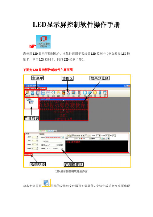
LED显示屏控制软件操作手册☞您使用LED显示屏控制软件,本软件适用于常规类LED控制卡(例如U盘LED控制卡,串口LED控制卡,网口LED控制卡等)。
下面为LED显示屏控制软件主界面图LED显示屏控制软件主界面双击光盘里面图标的安装包文件即可安装软件,安装完成后会在桌面出现图标,双击图标,即可进入LED显示屏控制软件的主界面。
☞下面是软件详细的操作说明控制卡查找和显示屏设置控制卡连接好显示屏和电脑后点击工具栏里面的查找屏查找屏使用串口卡或者网口卡连接会在红色字体区域自动显示控制卡的型号和版本号▲(注:使用U盘控制卡可以忽略查找屏步骤,直接设置屏参,编辑好节目点击发送即可)①点击屏参设置按钮设置屏参②输入密码168输入密码③设置好屏参后点击设置屏参按钮屏参设置▲(注:设置屏参里面有一些常用的单元板参数供参考选择)☞下面是一些常见的LED单元板的参数设置推荐1,如果是户外P10的屏,接口是12接口的:(单色)屏参为:数据极性:低,OE极性:高扫描方式: 1/4 扫描,默认4.1扫描方式2,如果是户外P16的屏,接口是12接口的:屏参为:数据极性:低,OE极性:高扫描方式: 1/4 扫描中的4.3扫描方式3,如果是户内φ3.75,φ5 的屏,接口是08接口的:屏参为:数据极性:低,OE极性:低扫描方式: 1/16 扫描4,如果是车载屏P7.62的屏,接口是08接口的:屏参为:数据极性:低,OE极性:低扫描方式: 1/8 扫描▲(注:以上推荐参数都是市面LED单元板的常见参数设置,不排除特殊规格的LED单元板,请以实际情况为准)编辑节目和节目类型介绍①设置好屏参后首先点击工具栏里面的节目按钮即可进入节目编辑节目②点击节目编号可以设置节目播放时段和次数③在工具栏选择不同的节目类型可以进一步详细编辑节目内容1.字幕型节目,在超文本RTF型文件节目中,RTF超文本可对每个字符设置字体、大小,不同的颜色,并可以单独保持该节目的超文本文件,以便以后恢复使用。
显示器操作指南说明书
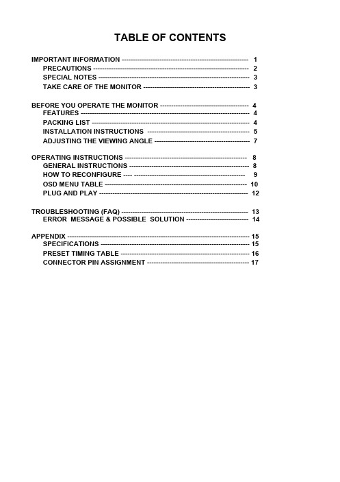
TABLE OF CONTENTSIMPORTANT INFORMATION --------------------------------------------------------- 1 PRECAUTIONS ---------------------------------------------------------------------- 2 SPECIAL NOTES -------------------------------------------------------------------- 3 TAKE CARE OF THE MONITOR ------------------------------------------------ 3BEFORE YOU OPERATE THE MONITOR ---------------------------------------- 4 FEATURES ---------------------------------------------------------------------------- 4 PACKING LIST ----------------------------------------------------------------------- 4 INSTALLATION INSTRUCTIONS ---------------------------------------------- 5 ADJUSTING THE VIEWING ANGLE ------------------------------------------- 7 OPERATING INSTRUCTIONS ------------------------------------------------------- 8 GENERAL INSTRUCTIONS ------------------------------------------------------ 8 HOW TO RECONFIGURE ---- -------------------------------------------------- 9 OSD MENU TABLE ---------------------------------------------------------------- 10 PLUG AND PLAY ------------------------------------------------------------------- 12TROUBLESHOOTING (FAQ) --------------------------------------------------------- 13 ERROR MESSAGE & POSSIBLE SOLUTION ---------------------------- 14 APPENDIX ---------------------------------------------------------------------------------- 15 SPECIFICATIONS ------------------------------------------------------------------- 15 PRESET TIMING TABLE ---------------------------------------------------------- 16 CONNECTOR PIN ASSIGNMENT ---------------------------------------------- 17IMPORTANT INFORMATIONBefore operating the monitor, please read this User Guide thoroughly. This User Guide should be retained for future reference.FCC Class B Radio Frequency Interference StatementWARNING: (FOR FCC CERTIFIED MODELS)NOTE: This equipment has been tested and found to comply with the limits for a Class B digital device, pursuant to Part 15 of the FCC Rules. These limits are designed to provide reasonable protection against harmful interference in a residential installation. This equipment generates, uses and can radiate radio frequency energy, and if not installed and used in accordance with the instructions, may cause harmful interference to radio communications. However, there is no guarantee that interference will not occur in a particular installation. If this equipment does cause harmful interference to radio or television reception, which can be determined by turning the equipment off and on, the user is encouraged to try to correct the interference by one or more of the following measures:1. Reorient or relocate the receiving antenna.2. Increase the separation between the equipment and receiver.3. Connect the equipment into an outlet on a circuit different from that to which the receiveris connected.4. Consult the dealer or an experienced radio/TV technician for help.NOTICE:1. The changes or modifications not expressly approved by the party responsible forcompliance could void the user's authority to operate the equipment.2. Shielded interface cables and AC power cord, if any, must be used in order to complywith the emission limits.3. The manufacturer is not responsible for any radio or TV interference caused byunauthorized modification to this equipment. It is the responsibilities of the user to correct such interference.As an E NERGY S TAR®Partner our company has determined that this product meets the E NERGY S TAR® guidelines for energy efficiency.WARNING:To prevent fire or shock hazard, do not expose the monitor to rain or moisture. Dangerous high voltages are present inside the monitor. Do not open the cabinet. Refer servicing to qualified personnel only.PRECAUTIONSl Do not use the monitor near water, e.g. near a bathtub, washbowl, kitchen sink, laundry tub, swimming pool or in a wet basement.l Do not place the monitor on an unstable cart, stand, or table. If the monitor falls, it can injure a person and cause serious damage to the appliance. Use only a cart or stand recommended by the manufacturer or sold with the monitor. If you mount the monitor on a wall or shelf, use a mounting kit approved by the manufacturer and follow the kit instructions.l Slots and openings in the back and bottom of the cabinet are provided for ventilation. To ensure reliable operation of the monitor and to protect it from overheating, be sure these openings are not blocked or covered. Do not place the monitor on a bed, sofa, rug, or similar surface. Do not place the monitor near or over a radiator or heat register. Do not place the monitor in a bookcase or cabinet unless proper ventilation is provided.l The monitor should be operated only from the type of power source indicated on the label.If you are not sure of the type of power supplied to your home, consult your dealer or local power company.l The monitor is equipped with a three-pronged grounded plug, a plug with a third (grounding) pin. This plug will fit only into a grounded power outlet as a safety feature. If your outlet does not accommodate the three-wire plug, have an electrician install the correct outlet, or use an adapter to ground the appliance safely. Do not defeat the safety purpose of the grounded plug.l Unplug the unit during a lightening storm or when it will not be used for long period of time.This will protect the monitor from damage due to power surges.l Do not overload power strips and extension cords. Overloading can result in fire or electric shock.l Never push any object into the slot on the monitor cabinet. It may short circuit parts causing a fire or electric shock. Never spill liquids on the monitor.l Do not attempt to service the monitor by yourself; opening or removing covers can expose you to dangerous voltages and other hazards. Please refer all servicing to qualified service personnel.l To ensure satisfactory operation, use the monitor only with UL listed computers which have appropriate configured receptacles marked between 100 - 240V AC, Min. 5A.l The wall socket shall be installed near the equipment and shall be easily accessible.SPECIAL NOTESThe following symptoms are normal with the monitor and do not indicate a problem.•Due to the nature of the fluorescent light, the screen may flicker during initial use. Turn off the Power Switch and then turn it on again to make sure the flicker disappears.•You may find slightly uneven brightness on the screen depending on the desktop pattern you use.•The LCD screen has effective pixels of 99.99% or more. It may include blemishes of0.01% or less such as a missing pixel or a pixel lit all the time.•Due to the nature of the LCD screen, an afterimage of the previous screen may remain after switching the image, when the same image is displayed for hours. In this case, the screen is recovered slowly by changing the image or turning off the Power Switch for hours.•When the screen becomes black or flashing, or cannot illuminate any more, contact your dealer or service center to replace parts. Don’t repair the screen by yourself!TAKE CARE OF THE MONITOR•Do not install the monitor in a location near heat sources such as radiators or air ducts, or in a place subject to direct sunlight, or excessive dust or mechanical vibration or shock. •Save the original shipping carton and packing materials, as they will come in handy if you ever have to ship your monitor.•For maximum protection, repackage your monitor as it is originally packed in the factory. •To maintain cleanness of your LCD display, wipe it periodically with clean and soft cloth.The screen may be damaged by any liquid splash.•To keep the monitor looking new, periodically clean it with a soft cloth. Stubborn stains may be removed with a cloth lightly dampened with mild detergent solution. Never use strong solvents such as thinner, benzene, or abrasive cleaners, since these will damage the cabinet. As a safety precaution, always unplug the monitor before cleaning it.BEFORE YOU OPERATE THE MONITOR FEATURES•43.2cm(17”) TFT Color LCD Monitor.•Recommended Resolutions: SXGA 1280 X 1024 @60Hz.•8ms (Tr+Tf) Quick Response Time.•SPLENDID™ Video Enhancement Technology.• 5 Video Preset Modes Switiched by Hotkey• 3 Skin-Tones Selection for Users’ Preference.•Microsoft Windows 95/98/2000/XP Compliance•VESA Display Data Channel (DDC)1/2B Compliance •VESA Wall Mount Compliance (100x100mm).•EPA ENERGY STAR® and Ergonomic Design.•Cabel Binder and Compact Case Design for Space Saving. •Both VGA and DVI-D Inputs. (for MM17T only)• 1.2Wx2 Stereo Speakers / Earphone Jack. (for MM17T only) PACKAGE LISTThe product package should include the following items:1. LCD Monitor2. Quick Start Guide3. User Guide (CD)4. Power Cord5. VGA Cable6. Audio Cable (for MM17T only)INSTALLATION INSTRUCTIONSASSEMBLING THE MONITOR BASEInstall RemoveFigure 1POWER CORD / POWER SOURCE1. Make sure that the power cord is the correct type required in your area.2. This LCD monitor has an internal universal power supply that allows operation in either100/120V AC or 220/240V AC voltage area (No user adjustment is required.)3. Connect the power cord into your LCD monitor’s power input socket, and then plug theother end into a 3-pin AC power outlet. The power cord may be connected to either a wall power outlet or the power outlet socket on your PC, depending on the type of power cord supplied with your LCD monitor.NOTESA certified power supply cord has to be used with this equipment. The relevant national installation and/or equipment regulations shall be considered. A certified power supply cord not lighter than ordinary polyvinyl chloride flexible cord according to IEC 60227 (designation H05VV-F 3G 0.75mm2 or H05VVH2-F2 3G 0.75mm2) shall be used. Alternative a flexible cord be of synthetic rubber according to IEC 60245 (designation H05RR-F 3G 0.75mm2) shall be used.MAKING THE CONNECTIONSConnecting the Signal Cable:Plug one end of the VGA Cableto the LCD monitor’s VGA port, the other end to the computer's VGA socket and tighten the two screws on the cable connector. Moreover, for MM17T, you can buy an extra 24-Pin DVI-D cable from your dealer for the digital signal connection if preferred.Connecting the Power Cord: Plug one end of the AC-power cord to the LCD monitor’s AC input socket, the other end to the power outlet.Connecting the Audio Cable (MM17T only):Plug the audio cable between the computer multi-media (or audio) card's audio output and monitor's audio jack.Caution:If the AC outlet is not grounded (with three holes), install the proper grounding adapter (not supplied).Figure 21. AC Input Socket2. Audio Jack (MM17T only)3. DVI-D Port (MM17T only)4. VGA (D-SUB) Port5. Earphone Jack (MM17T only)6. Cable BinderADJUSTING THE VIEWING ANGLE•For optimal viewing it is recommended to look at the full face of the monitor, then adjust the monitor’s angle to your own preference.•Hold the stand so you do not topple the monitor when you change the monitor’s angle. •You are able to adjust the monitor’s angle from -5° to 20°.Figure 3NOTES•Do not touch the LCD screen when you change the angle. It may cause damage or break the LCD screen.•Careful attention is required not to catch your fingers or hands when you change the angle.OPERATING INSTRUCTIONSGENERAL INSTRUCTIONSPress the power button to turn the LCD monitor on or off. The other control buttons are located on the front bezel (See Figure 4). By changing these settings, the picture can be adjusted to your personal preferences.•The power cord should be connected.•Connect the signal cable from the LCD monitor to your computer.•Press the power button to turn on the LCD monitor. The power indicator will light up.Figure 41. SPLENDID™ Button :•Hotkey for switching between 5 advanced video preset modes (Scenery Mode, Standard Mode, Theater Mode, Game Mode, Night Mode) with SPLENDID™Video Enhancement Technology.•Automatically adjust the image to its optimized position, clock, and phase by pressing the button for 2 seconds.•Exit the OSD menu or go back to the previous menu as the OSD menu is active.Button :2. -•Decrease the level of the function selected or move to the previous function as the OSD menu is activated.3. Power Button / Power LED Indicator:•Switch the LCD monitor on or off.•LED lights blue(MM17T)/green(MM17D): normal operation mode.•LED lights amber: power saving mode.•LED is off: power off mode.4. +•Activate Brightness adjustment menu.•Increase the level of the function selected or move to the next function as the OSD menu is activated.5. Menu Button :•Activate the OSD (On-Screen Display) main menu.•Enter/select the icon(function) highlighted as the OSD menu is activated.HOW TO RECONFIGURE1. Press the MENU-button to activate the OSD main menu (Figure 5).2. Pressto change the settings of the selected function.3.4. To exit and save, select the exit function. If you want to adjust any other function, repeatsteps 2-3.Figure 5OSD MENU TABLEThe table describes the function of each OSD iconMain Menu ItemMain Menu Icon Sub Menu Item SubMenuIconDescriptionSceneryModeAdvance for general Windows use (SPLENDID ™Off) Theater ModeAdvance for game use withSPLENDID ™ Video EnhancementScenarioAdvance for dark-display use withSPLENDID™ Video EnhancementColor RAdjust greengain RGBAdjust blue gainReddishSelect natural skin stone SkinToneSelect yellowishskin stone CoolNormal imagecolor. (7500°K) Color AdjustWarmAdjust brightness levelLuminanceAdjust contrast levelOSD SetupAdjust horizontal position of theOSDOSD V-PositionAdjust OSD timeout PhaseClockAdjust horizontal position of theimage Image PositionAdjust verticalposition of theimage Image SetupAutomatically adjust the horizontal /vertical positions, phase and clock of the image Input SelectShow the resolution,H/V frequency and input port of current input timing LanguageRecall default setting ExitPLUG AND PLAYPlug & Play DDC2B FeatureThis monitor is equipped with VESA DDC2B capabilities according to the VESA DDC STANDARD. It allows the monitor to inform the host system of its identity and, depending on the level of DDC used, communicate additional information about its display capabilities.The DDC2B is a bidirectional data channel based on the I²C protocol. The host can request EDID information over the DDC2B channel.THIS MONITOR WILL APPEAR TO BE NON-FUNCTIONAL IF THERE IS NO VIDEO INPUT SIGNAL. TO OPERATE PROPERLY, THERE MUST BE VIDEO INPUT SIGNAL. This monitor meets the Green monitor standards as set by the Video Electronics Standards Association (VESA) and/or the United States Environmental Protection Agency (EPA) and The Swedish Confederation Employees (NUTEK). This feature is designed to conserve electrical energy by reducing power consumption when there is no video-input signal present. When there is no video input signal this monitor, following a time-out period, will automatically switch to an OFF mode. This reduces the monitor's internal power supply consumption. After the video input signal is restored, full power is restored and the display is automatically redrawn. The appearance is similar to a "Screen Saver" feature except the display is completely off. The display is restored by pressing a key on the keyboard, or clicking the mouse.USING THE RIGHT POWER CORD :The accessory power cord for the Northern American region is the wallet plug with NEMA 5-15 style and is UL listed and CSA labeled. The voltage rating for the power cord shall be 125 volts AC.Supplied with units are intended for connection to power outlet of personal computer: Please use a cord set consisting of a minimum No. 18 AWG, type SJT or SVT three conductors flexible cord. One end terminates with a grounding type attachment plug, rated 10A, 250V, CEE-22 male configuration. The other end terminates with a molded-on type connector body, rated 10A, 250V, having standard CEE-22 female configuration.Please note that power supply cord needs to use VDE 0602, 0625, 0821 approval power cord in European counties.TROUBLESHOOTING (FAQ)Problem & Question Possible SolutionPower LED is not ON l Press the Power Button to check if themonitor is in the ON mode.l Check if the Power Cord is properlyconnected the monitor and the poweroutlet.The Power LED lights amber and there is no screen image l Check if the monitor and the computer are in the ON mode.l Make sure the Signal Cable is properly connected the monitor and the computer. l Inspect the Signal Cable and make sure none of the pins are bent.l Connect the computer and another available monitor to check if the computer is properly working.Screen image is too light or dark l Adjust the Contrast and Brightness settings via OSD.Screen image is not centered or sized properly l Press the SPLENDID™ Button for 2 seconds to automatically adjust theimage.l Adjust the H-Position or V-Position settings via OSDScreen image bounces or a wave pattern is present in the image l Make sure the Signal Cable is properly connected the monitor and the computer. l Move electrical devices that may cause electrical interference.Screen image has color defects(white does not look white) l Inspect the Signal Cable and make sure that none of the pins are bent.l Perform Reset via OSD.l Adjust the R/G/B color settings or select the Color Temperature via OSD.Screen image is blurry or fuzzy l Press the SPLENDID™ Button for 2 seconds to automatically adjust theimage.l Adjust the Phase and Clock settings via OSD.No sound or sound is low (MM17T only). l Ensure that the Audio Cable is properly connected the monitor and the computer l Adjust the volume settings of both your monitor and computer.l Ensure the computer sound card driver is properly installed and activated.ERROR MESSAGE & POSSIBLE SOLUTIONNO SIGNAL︰1. Check that the signal-cable is properly connected , If the connector is loose, tighten theconnector’s screws.2. Check the signal-cable’s connection pins for damage.OUT OF RANGE︰Your computer has been set to unsuitable display mode ,set the computer to display mode given in the following Preset Timing Table.APPENDIXSPECIFICATIONSModel MM17T MM17DVisible Diagonals 17.0" (43.2cm)Screen Size Horizontal : 337.92mm, Vertical : 270.34mm Max. Resolution SXGA 1280x1024@75HzPixel Pitch 0.264mmBrightness 300cd/㎡ (Typ.), 400cd/㎡ (Max.)Contrast Ratio 500:1 (Typ.), 600:1 (Max.)Viewing Angle (CR≧10) 150°(H)/ 130°(V)Display Colors 16.2MResponse Time 8msSignal Frequency Horizontal: 30~80 kHz, Vertical: 55 ~ 75HzMax. Pixel Clock 135MHzPlug & Play VESA DDC2B TMVideo Input DVI-D & D_Sub D_SubAudio Input/ Earphone 3.5mm Mini-jack --Speaker (Built-in) 1.2W x 2 Stereo --Tilt +20°~ -5°VESA Wall Mount 100x100mmPower Source 100~240VAC,47~63HzPower Consumption Power On: <40W, Standby: <2WPhys. Dimension 380(W) x 390(H) x 180mm(D)Net Weight 4 kg (approx.)Environmental Conditions Operating Temp: 5° to 35°C Storage Temp.: -20° to 60°C Operating Humidity: 10% to 85%Regulatory Approvals TCO99, Energy Star, UL/cUL, TUV-GS, CB, CE, FCC, CCC, BSMI, Gost-R, C-Tick, VCCI,ISO13406-2 ClassIIPRESET TIMING TABLESTANDARD RESOLUTION HORIZONTALFREQUENCYVERTICALFREQUENCYDos-mode 640 × 350 31.47kHz 70Hz Dos-mode 720 × 400 31.47kHz 70Hz640 × 480 31.47kHz 60Hz640 × 480 35.00kHz 66.6Hz640 × 480 37.50kHz 75Hz VGA640 × 480 37.86kHz 72Hz800 × 600 37.879kHz 60Hz800 × 600 46.875kHz 75Hz800 × 600 35.16kHz 56Hz800 × 600 48.01kHz 72Hz SVGA832 × 624 49.725kHz 75Hz1024 × 768 48.363kHz 60Hz1024 × 768 56.476kHz 70Hz XGA1024 × 768 60.02kHz 75Hz1280 × 1024 64.00kHz 60Hz SXGA1280 × 1024 80.00kHz 75HzCONNECTOR PIN ASSIGNMENT15 - Pin Color Display Signal CablePIN NO.DESCRIPTION PIN NO.DESCRIPTION 1. Red 9. +5V2. Green 10. Detect Cable3. Blue 11. RXD4. TXD 12. DDC-Serial Data5. Ground 13. H-Sync6. R-Ground 14. V-Sync7. G-Ground 15. DDC-Serial Clock 8.B-Ground24 - Pin Color Display Signal Cable(MM17T only)PIN NO. DESCRIPTIONPI N NO.DESCRIPTION 1. TMDS Data 2- 13. TMDS Data 3+ 2. TMDS Data 2+ 14. +5V Power 3. TMDS Data 2/4 Shield15. Ground(for+5V)4. TMDS Data 4- 16. Hot Plug Detect5. TMDS Data 4+ 17. TMDS Data 0-6. DDC Clock 18. TMDS Data 0+7. DDC Data 19. TMDS Data 0/5Shield8. N.C. 20. TMDS Data 5- 9. TMDS Data 1- 21. TMDS Data 5+ 10. TMDS Data 1+ 22. TMDS Clock Shield 11. TMDS Data 1/3 Shield23. TMDS Clock +12. TMDS Data 3- 24. TMDS Clock -。
大屏幕操作手册
第一章.硬件设备简介1.1光源1.2接口接口输入端口的定义:输出通道0口可输出输入通道0或输入通道1信号,输出通道1口只能输出输入通道1信号.零通道输入端口的定义:1.3投影单元结构投影单元光学成像结构如下图2.1:反射镜成像幕投影机投影机 等效位置调整架调节螺母调整架调节螺母1) 投影机的光程决定图像的大小。
2) 投影机的投射角决定图像的方正形状。
3) 反射镜会影响上述因素。
第二章.控制软件的登陆步骤1.双击控制PC桌面的VWASExplorer图标,就会弹出下(图1)所示登录界面,(图1)在用户名输入:“ADMIN”;在密码输入:“111111”按“确定”即可进入管理软件菜单。
如下图(图2)(图2)步骤2.右击右面:(图4)步骤3.然后点击“打开所有机芯”即可点亮大屏幕【大约2分钟才亮起来】。
第三章.屏幕管理软件操作3.1 信号的调用:添加信号源点击信号源图标在信号源栏点击右键,选择菜单“添加信号源”,弹出如下图所示的信号源属性对话框。
在“名称”栏填入信号源的名字,在“输出”栏选择信号类型,信号的类型主要有:DRGB、ARGB、HDTV、SVIDEO、VIDEO、VLINK、音频、USER_CUSTOM、网络摄像头和DVS。
在“制式”栏选择信号的制式。
注意:某些类型的信号源可能没有制式,如DRGB。
若该信号源为可控制设备(如摄像头),选中复选框“可被外部程序控制”后,该信号源将可以被信号源控制程序控制。
用户还可以根据需要把一个或多个信号源放在一个“组”中。
“组”是指多个具有某种相同属性的信号源归类或集合。
通过使用组对不同类型的信号源进行分门别类地管理,可以让用户对信号源的操作和管理更加方便和快捷。
要添加组,可以在信号源栏上点击鼠标右键,在弹出的菜单中选择“添加组”,弹出组属性对话框。
3.2“模式”的使用:添加模式在“模式”栏点击右键,在弹出的左键菜单中选择“添加”项,将弹出如下图所示的模式属性对话框:首先填写的是该模式的名称,用于唯一识别该模式。
- 1、下载文档前请自行甄别文档内容的完整性,平台不提供额外的编辑、内容补充、找答案等附加服务。
- 2、"仅部分预览"的文档,不可在线预览部分如存在完整性等问题,可反馈申请退款(可完整预览的文档不适用该条件!)。
- 3、如文档侵犯您的权益,请联系客服反馈,我们会尽快为您处理(人工客服工作时间:9:00-18:30)。
3 脚 DC 电源端子
第6页共6页
POP-D 文本显示器用户手册 V1.0
POP-D 双串口文本显示器的端口定义(ARM):
COM1 端口 9 芯阳座(兼程序下载端口,RS232/RS422/RS485)
1
GND
2 3 4 5 6 7 8 9 COM2 端口 9 芯阴座 RS232/RS485 1 2 3 4 5 6 7 8 9
POP-D文本显示器可编程显示屏的前面板如下图(实物图):
POP-D 文本显示器的背面装有 DC 电源端子,通讯插座,背面有 LCD 对比度调整电位 器;如下图示:
第5页共5页
POP-D 文本显示器用户手册 V1.0
下载用户工程文件数据时,使用随机提供的 RS232 通讯电缆(JB-CAB-PC)将 POP 文本 显示器的 RS232 通讯端口和个人计算机的串行通讯端口连接起来。文本显示器和用户串口 设备通讯时,必须根据所连接串口设备的类型来选择不同的通讯电缆。
1.3 产品结构及定义
POP-D文本显示器的前面板除液晶LCD 显示窗之外,还有 22 个薄膜开关按键,该按 键触摸手感好、使用寿命长。按键的基本功能包括:串口设备寄存器的数值输入,报警记录
第4页共4页
POP-D 文本显示器用户手册 V1.0
查询、清除,监控画面翻页、转换等。同时,该22个按键还能通过软件定义,扩展成31个 键的功能,用来完成工程画面跳转,字、位状态设定等功能。另外在标准型POP文本显示器 的右上角有三个 LED 状态指示灯, 用来显示文本显示器的电源、运行、通讯三个状态,方便 用户了解POP文本显示器的工作情况。
第3页共3页
* 支持多种串口标准
POP-D 文本显示器用户手册 V1.0
COM1:支持 RS232/RS485/RS422, COM2:支持 RS232/RS485
* 功能强大的画面组态软件:JB_HMI_D
1.2 产品规格
电气规格
输入电压
DC12V-DC28V
功耗
RXD TXD RXGND RX+ TXNC TX+
GND RXD TXD NC GND NC B(-) NC A(+)
PC 机 RS232 串口引脚定义: 引脚号 1 2 3 4 5 6 7 8 9
定义 DCD RXD TXD DTR GND DSR RTS CTS
RI
2.6
POP文本显示器中的寄存器数值转换 .........................................................24
第2页共2页
POP-D 文本显示器用户手册 V1.0
第 1 章 POP-D 型文本显示器硬件概述
1.1 基本描述
第8页共8页
1.5 键盘功能列表
POP-D 文本显示器用户手册 V1.0
按键名称 1~9
(F1~F9) 0
(F10) ± (.)
CLR
HOME ESC
SHF
ALM
SET
ENT ▲ ▼ ◄ ►
按键功能 用于输入数字 1~9 或定义为功能键(软件中设置)。 F1~F9 可定义为功能键(软件中设置),由“SHF+X”来实现功能;如果有密码 保护,则需要先输入密码,并按下“ENT”进行确认。 用于输入数字 0 或定义为功能键(软件中设置)。 F10 可定义为功能键(软件中设置),由“SHF+X”来实现功能;如果有密码保 护,则需要先输入密码,并按下“ENT”进行确认。 可定义为功能键(软件中设置)。
低于4W (TYP2.0W)
允许瞬时停电 小于20ms
耐电压
AC1000V-10MA 1 分钟(信号与地间)
绝缘阻抗
DC500V-约10M Ω (信号与地间)
环境条件
工作温度 保存温度 环境湿度 耐振动 抗干扰 周围空气 保护结构
0~50 ℃ –10~60 ℃ 20~85%(无凝露) 10~25Hz(X、Y、Z 方向各 30 分钟 2G) 电压噪声:1000Vp-p ,50ns 无腐蚀性气体 适合 IP65F
2.3
时钟设定的两种方法 ...................................................................................11
2.4
JB_HMI_D软件中的数据传输设置..............................................................12
首先感谢您购买、并使用本公司人机界面产品POP文本显示器 !
POP(Power Operation Panel或音乐中的Popular)文本显示器是连接可编程序控制器 (PLC)或具有串口通讯能力电气设备的小型人机界面 (HMI) 产品,它能以文字、数据、指示 灯、图形、图片等基本元素来完成所连接串口设备的数据显示、状态显示、数据输入等功能, 从而使设备的操作人员能够实时监控设备的运行情况。 POP-D型文本显示器是国内市场首款基于32位ARM处理器的高速、大容量双串口文本显示 器,该型文本显示器使用新的画面组态软件JB_HMI_D,支持实时时钟、配方、双串口数据 互通等功能,支持两个不同串口设备连接,工程画面最大容量达3MB。双串口文本显示器的 基本功能同我公司标准的A型文本显示器,基本功能的使用请参考我们的“POP文本显示器 用户手册V6.0”,本手册仅介绍D型双串口文本显示器增加的独有功能!
1.1
基本描述 .......................................................................................................3
1.2
产品规格 .......................................................................................................4
在输入寄存器数值时,设定数值的小数点;
若与“SHF”键同时按下可实现符号“±”的输入。 可定义为功能键(软件中设置)。 在输入寄存器数值或密码时,清除键入的数值; 在查询报警记录的状态下,可按此键清除报警记录。 基本功能为任何情况下按此键回到开机画面,可定义为功能键(软件中设置)。 当出现下载错误并且无法正常启动的情况下,可在上电时与“SHF”键同时按下 直接进入下载模式。 退出现有操作,例如寄存器设定、密码输入、报警记录显示等状态。可定义为功 能键(软件中设置)。
2.1
部分元件属性的说明 ...................................................................................10
2.2
报警功能简介 .............................................................................................. 11
第7页共7页
JB-CAB-PC 电缆线(下载线)连接图:
POP-D 文本显示器用户手册 V1.0
注:请勿带电拔插设备的串口连接电缆!!!
1.4 外型尺寸及安装方法
POP-A / POP-D型文本显示器 外形尺寸:180 ×111 ×38 (单位:mm) 安装开孔尺寸:171×101 (单位:mm)
当 ESC、HOME、ALM、SET、ENT、↑、↓、←、→键被定义为功能键时,
可由“SHF+X”来实现原键的基本功能。 当出现下载错误并且无法正常启动的情况下,可在上电时与“HOME”键同时按 下直接进入下载模式。 按此键进入报警记录查询画面,每幅画面最多可显示 4 条报警记录,最多 16 幅 报警画面。当报警记录多于 4 条,可重复按此键在报警画面之间切换。可定义为 功能键(软件中设置) 按下此键可进行寄存器数值设定,当前可设定的寄存器将会反色显示,表示可输 入数值;输入结束后用“ENT”键将该数值写入 PLC,同时,自动跳至下一个 需要设定的寄存器;重复上述操作,可实现画面中所有的寄存器设定。 如果有密码保护,则需要先输入密码,并按下“ENT” 键进行确认。 如果不按下“ENT”,而再次按下“SET”键,则当前输入的数值将不被写入 PLC, 而是直接跳至下一个需设定的寄存器,直至退出设定。 在寄存器设定的状态下,可以直接按“ESC” 键退出设定。 可定义为功能键(软件中设置) 寄存器数值设定或密码设定的情况下,按此键进行确认。 可定义为功能键(软件中设置) 切换至用户自定义的前一幅画面。可定义为功能键(软件中设置) 切换至用户自定义的下一幅画面。可定义为功能键(软件中设置) 在输入寄存器数值时,删除最低位数字。可定义为功能键(软件中设置) 可定义为功能键(软件中设置)。
2.5.1 配方选项..............................................................................................15
2.5.2 配方功能的使用方法............................................................................17
2.4.1 数据传输功能的应用 1——PLC和变频器之间的寄存器数据相互映射 .13
2.4.2 数据传输功能的应用 2——远端PC机监控现场的PLC寄存器数据 .......14
2.5
配方功能说明..............................................................................................15