CHTM-02N 系列温湿度传感器说明书
WHTM-02 电压式温湿度传感器模块
温度(℃)
-10
0
10 20 30 40 50 60 70
0~1V 输出 0.1 0.2 0.3 0.4 0.5 0.6 0.7 0.8 0.9
0~3V 输出 0.3 0.6 0.9 1.2 1.5 1.8 2.1 2.4 2.7
0~3.3V 输出 0.33 0.66 0.99 1.32 1.65 1.98 2.31 2.64 2.97
四、命名规则
W H T M -- 02 /
公司代号 湿度 温度 类别
系列号
XXX
温敏元件 D:DS18B20 L:LM35 N :NTC
五、外形尺寸
A
输出范围 A:0-1 V B:0-3 V C:0-3.3 V D:0~5 V
PCB 尺寸图
-3-
外观图
广州贝丰电子科技有限公司
六、接线示意图(正面朝上,端子端靠右)
0~5V 输出 0.5 1.0 1.5 2.0 2.5 3.0 3.5 4.0 4.5
注:可按客户要求定制:温度检测范围和电压输出范围 模拟量线性输出图表:
湿度输出曲线图
温度输出曲线图
-2-
广州贝丰电子科技有限公司
9)数字量输出方式: 1、TTL 串口信号输出; 2、485 差分信号输出 (特殊定制) ; 数字量输出方式对应的控制协议和接口方式向厂家索要。
广州贝丰电子科技有限公司
WHTM-02 型 温湿度传感器规格书
一、原理
利用集成 IC 采样温度、湿度敏感器件的原始数据,再通过特定算法对湿敏器件随温 度和湿度变化的,非线性阻抗特性进行温度补偿、线性修正、校准,使得温度、湿度敏 感器件的非线性阻抗特性,变换成线性模拟量输出或者线性数字量输出。(输出方式:模 拟量输出或数字量输出可选,具体见输出特性表)
温度传感器说明书

DimensionalDrawings 4
Electricalconnection|HeadBig
Headunitwith1transmitter n( odisplay)andM12plug
Headunitwith1transmitter n( odisplay)andcablegland
V01
B
52.7 / 2.09
V52
F
66.0 / 2.60
V04
N
84.0 / 3.31
D2 [mm/inch] 31.0 / 1.22 50.0 / 1.97 68.0 / 2.68
FOOD
Processconnectionswithextendedtemperaturerange
CH|1 CLEANadaptM21
6mm
t50¡1.8s t90¡5.2s D: 8, 10, 12 mm
D
4mm
t50¡1.2s t90¡3.5s D: 6, 8, 10 mm
D
3mm
t50¡0.8s t90¡s2. D: 6 mm
D
4
3
d
Front“- ush t50¡2.5s t90¡15s
14 [0.55]
7 Installation|Warnings
Disposal
· Electrical devices should not be disposed of with household trash. They must be recycled in accordance with national laws and regulations.
· Take the device directly to a specialized recycling company and do not use municipal collection points.
CHTM02温湿度传感器手册

1、说明此份资料适用于型号为CHTM-02/N的温湿度模块。
产品标志“CHM-02/N”2、参数3、电气特性1)敏感元件(湿度):高分子湿敏电阻“CHR-01”2)供电:5V±5%3)耗电电流:5mA max.(2mA avg.)4)工作范围:温度0~60℃湿度10% -- 95%RH5)储存条件:温度0-50℃湿度60%RH6)湿度变送范围:0~100%RH7)精度(湿度准确度):±5%RH (在25℃,输入电压=5V)一致性:±3%RH/每批8)输出信号:(对应0~100%RH,在25℃,输入电压=5V下)型号:CHTM-02/NA 0 — 3V型号:CHTM-02/NB 1 — 3V型号:CHTM-02/NC 0 – 1V9)温度系数: 0.4%RH/℃(输入电压=5V,30~80%RH温度范围10~40℃(基准点25℃)10)电源电压范围: 4.75~5.25V (基准点5V,±5%)11)敏感元件(温度):NTC 热敏电阻(可选)LM35,TMP35 (可选)12)温度输出信号:可选热敏电阻或集成温度传感器,电路板上已经预留焊接位置热敏电阻:NTC R(25℃)=10KΩ±5%,B值(25/50℃)=3950K±2% (NTC 具体阻值与B 值可按用户指定,焊接位置可选择接地或接+5V)集成温度传感器(3 PIN +5V,T,GND )推荐型号:LM35,TMP35:0--100℃输出0 – 1V 4、标准测试条件㈠测试条件:室温25℃,电压5V,在需测试的湿度环境下放置15分钟,测试模块电压。
㈡测试仪器1)湿度发生器:高精度恒温恒湿试验箱巨孚2)标准:GE公司光电露点仪3)电压表HP5、可靠性测试:通过常规冲击试验,振动试验,冷热试验,高湿试验,温度循环等试验6、包装1)盒装,提供散包装,形式不限。
2)参数表,合格证,生产日期标志。
温湿度传感器产品说明书
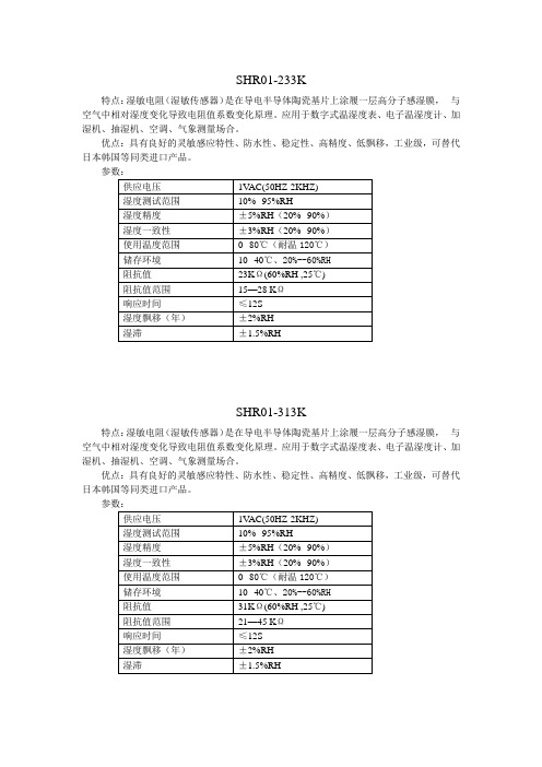
特点:湿敏电阻(湿敏传感器)是在导电半导体陶瓷基片上涂履一层高分子感湿膜,与空气中相对湿度变化导致电阻值系数变化原理。
应用于数字式温湿度表、电子温湿度计、加湿机、抽湿机、空调、气象测量场合。
优点:具有良好的灵敏感应特性、防水性、稳定性、高精度、低飘移,工业级,可替代日本韩国等同类进口产品。
SHR01-313K特点:湿敏电阻(湿敏传感器)是在导电半导体陶瓷基片上涂履一层高分子感湿膜,与空气中相对湿度变化导致电阻值系数变化原理。
应用于数字式温湿度表、电子温湿度计、加湿机、抽湿机、空调、气象测量场合。
优点:具有良好的灵敏感应特性、防水性、稳定性、高精度、低飘移,工业级,可替代日本韩国等同类进口产品。
特点:湿敏电阻(湿敏传感器)是在导电半导体陶瓷基片上涂履一层高分子感湿膜,与空气中相对湿度变化导致电阻值系数变化原理。
应用于数字式温湿度表、电子温湿度计、加湿机、抽湿机、空调、气象测量场合。
优点:具有良好的灵敏感应特性、防水性、稳定性、高精度、低飘移,高性价比,可替代日本神荣、北陆、韩国等同类进口产品。
SHR02-313K特点:湿敏电阻(湿敏传感器)是在导电半导体陶瓷基片上涂履一层高分子感湿膜,与空气中相对湿度变化导致电阻值系数变化原理。
应用于数字式温湿度表、电子温湿度计、加湿机、抽湿机、空调、气象测量场合。
优点:具有良好的灵敏感应特性、防水性、稳定性、高精度、低飘移,高性价比,可替代日本神荣、北陆、韩国进口等同类产品。
特点:湿敏电阻(湿敏传感器)是在导电半导体陶瓷基片上涂履一层高分子感湿膜,与空气中相对湿度变化导致电阻值系数变化原理。
应用于数字式温湿度表、电子温湿度计、加湿机、抽湿机、空调、气象测量场合。
优点:具有良好的灵敏感应特性、防水性、稳定性、高精度、低飘移,高性价比,可替代日本神荣、北陆、韩国进口等同类产品。
特点:电容式温湿度模块是将湿度传感器非线性电阻值转换为线性电压信号输出,体积小,使用方便,精度高。
温湿度传感器说明书
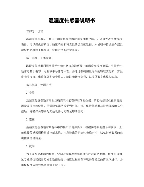
温湿度传感器说明书首部分:引言温湿度传感器是一种用于测量环境中温度和湿度的仪器。
它采用先进的技术和设计,可以提供高精度、快速响应和可靠性的温湿度数据。
本说明书将详细介绍温湿度传感器的工作原理、使用方法和注意事项。
第一部分:工作原理温湿度传感器利用测量元件和电路来获取环境中的温度和湿度数据。
测量元件通常是基于电容、电阻或半导体等原理,并通过准确测量元件的物理变化来计算温度和湿度值。
电路部分则负责放大、滤波和转换信号,以提供数字或模拟输出。
第二部分:使用方法1. 安装温湿度传感器通常需要正确安装才能获得准确的数据。
请将传感器放置在需要测量温湿度的位置,尽量避免遮挡或受到外部干扰。
保持传感器与被测区域的充分接触,并确保传感器与其他设备之间有足够的空间。
2. 连接温湿度传感器通常具有标准的接口和电源要求。
根据传感器的型号和要求,正确连接传感器到检测或控制系统。
注意接线的正确性和稳定性,以免影响数据的准确性和传输质量。
3. 校准为了获得更准确的数据,定期对温湿度传感器进行校准是必要的。
校准可以通过专业的仪器或参照标准数据进行。
校准过程应在环境条件稳定的情况下进行,并确保校准后的传感器能够正常工作。
第三部分:注意事项1. 温度和湿度范围不同型号和品牌的温湿度传感器具有不同的工作范围。
在选择和使用传感器时,请仔细阅读产品说明书,并确保传感器的工作范围符合您的需求。
超出工作范围可能导致数据的不准确或传感器的损坏。
2. 清洁和保养保持温湿度传感器的清洁和正常维护是确保长期准确运行的关键。
定期清理传感器表面和连接器,避免灰尘、污垢或液体进入传感器内部。
避免使用有害的化学物质清洁传感器,以免对其性能造成损害。
3. 环境干扰外部环境的干扰可能影响温湿度传感器的工作精度和稳定性。
避免将传感器放置在极端条件下,如强烈日光照射、高温高湿或强电磁场环境。
同时,避免传感器受到机械冲击或震动。
结尾部分:总结与展望温湿度传感器是现代生活中广泛应用的仪器,它可以在工业、农业、医疗、环境监测等领域发挥重要作用。
温湿度传感器产品说明书
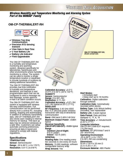
Dimensions: 55 W x 133 H x 33 mm D (2.2 x 5.25 x 1.3")
Enclosure Material: ABS Plastic
To Order
Model No.
Description
OM-CP-THERMALERT-RH
Wireless humidity and temperature transmitter
OM-CP-THERMALERT-RH-CERT Wireless humidity and temperature transmitter with NIST calibration certificate
Ordering Example: OM-CP-THERMALERT-RH-CERT, wireless humidity and temperature transmitter with NIST calibration certificate and OM-CP-RFC1000-EXT, wireless transceiver package.
OM-CP-RFC1000-IP69K Splash proof (IP69K) wireless transceiver package includes RF transceiver, USB cable, Windows software and operator’s manual (not CE approved)
Specifications
Temperature
Sensor: Semiconductor
Honeywell CHT温湿度变送器 说明书
传感与控制技术指标相对湿度湿度传感器: HIH3610 (烧结滤网保护)测量范围: 0∼100%RH输出: 4∼20mA(两线制)0∼5V(三线制)精度: ± 3%RH (@25°C, 0~100%RH)总精度:± 5%RH (0∼40°C,20∼80%RH范围内的综合精度)长期稳定性: ± 1%RH/年温度温度传感器: Pt1000 IEC751 class B测量范围: -20°C∼+85°C或-10°C∼+60°C输出: 4∼20mA(两线制)0∼5V(三线制)精度: ± 0.3°C (@25°C)总精度:± 0.5°C (0∼40°C)长期稳定性: ± 0.25°C /年综述供电电源: 对4∼20mA输出: 7.5∼36VDC (标称24VDC)对0∼5V输出: 10∼30VDC (标称12VDC)负载电阻: 100-500Ω(4~20mA),>=1kΩ(0~5V)消耗电流: 最大40mA工作温度范围: -20°C∼+85°C或-10°C∼+60°C储存温度范围: -40°C∼+90°C外壳材料: ABS塑料外壳防护等级: IP30电磁兼容性: IEC61000-4-2, IEC61000-4-4, IEC61000-4-5输出曲线:外型尺寸:PCB 安装型: CHT3B**** 系列墙面安装型: CHT3W**** 系列! 注意事项:• 初次通电预热30分钟以上(考虑到电路自发热对传感器的影响)• 安装时应注意方向,“UP”箭头应朝上传感与控制霍尼韦尔公司上海办事处 上海市遵义路100号虹桥上海城B 座23楼 邮编:200051 中国 电话*************传真*************Email:***************************霍尼韦尔公司北京办事处 北京朝阳区宵云路28号 鹏润大厦17层B 区 邮编:100016 中国 电话*************传真*************Email:************************霍尼韦尔公司广州办事处 广州市海珠区滨江中路308号 海运大厦15楼AIJK 座 邮编:100016 中国 电话*************传真*************Email:************************霍尼韦尔公司香港办事处 香港北角英皇道225号国都广场霍尼韦尔大厦25楼 香港, 中国电话: +852-******** 传真: +852-******** Email:*************************质量保证及补救霍尼韦尔保证其制造的产品没有材料缺陷和不良工艺。
温度传感器使用说明
Executi ng division : Responsible division : Document type : Confidentiality status :HCN NVPTechnical Documentation InternalPrepared :Document state :08.02.2006 Czernietzki (NVP)Technology Transfer HCN PreliminaryChecked :09.02.2006 Czernietzki (NVP)FNC System BusinessThermistorsApproved :File:Revision :Language :Pages :09.02.2006 Czernietzki (NVP) TD-Thermistors-en-R001 001 en 1/19This document and its contents are the property of Hoppecke or its subsidiaries. This document contains confidential proprietary information. The reproduction,Document administration 文件管理Document History 文件记录VersionDateResponsibleReason of change001 08.02.2006 Czernietzki First release of the document.Change justifiable 变更审核Hans-Peter Czernietzki NVPPreparing , Checking , ApprovingLewis Liu HCN QS Preparing , Checking , ApprovingDocument generated with following tools 使用下列工具编写文件:WORD 200 <Grafic tool>Content 目录1 Overview Thermistors........................................................................................................................................................................2 1.1 General.....................................................................................................................................................................................2 1.2 NTC Thermistors.....................................................................................................................................................................4 1.3 PTC Thermistors......................................................................................................................................................................5 1.4 Lead wire configurations..........................................................................................................................................................6 1.5 Available temperature probe....................................................................................................................................................8 1.6 Available connection cables.....................................................................................................................................................8 2 Designs...............................................................................................................................................................................................9 2.1 Stainless steel block version.....................................................................................................................................................9 2.2 Electrolyte version...................................................................................................................................................................9 2.3 Connection cables..................................................................................................................................................................10 2.3.1 Two wire connection 414 220 0802.............................................................................................................................10 2.3.2 Four wire connection 414 220 0804............................................................................................................................10 2.3.3 Connection clamp........................................................................................................................................................10 2.4 Temperature curve PT100B...................................................................................................................................................11 2.5 Temperature curve NTC10K..................................................................................................................................................11 2.6 Technical data NTC10K.........................................................................................................................................................11 3 Attachments......................................................................................................................................................................................11 3.1 Drawing 2BZ60287-01..........................................................................................................................................................11 3.2 Drawing 3BZ60731-01..........................................................................................................................................................11 3.3 Drawing 2BZ60287-02..........................................................................................................................................................11 3.4 Drawing 3BZ60407-01..........................................................................................................................................................11 3.5 Drawing 3BZ60732-01..........................................................................................................................................................11 3.6 Drawing 3BZ60407-02. (11)1 Overview Thermistors电热调节器简介1.1 General总则Resistance elements come in many types conforming to different standards, capable of different temperature ranges, with various sizes and accuracies available. But they all function in the same manner: each has a pre-specified resistance value at a known temperature which changes in a predictable fashion. In this way, by measuring the resistance of the element, the temperature of the element can be determined from tables, calculations or instrumentation. These resistance elements are the heart of the RTD (Resistance Temperature Detector or short: Thermistor). Generally, a bare resistance element is too fragile and sensitive to be used in its raw form, so it must be protected by incorporating it into an housing.电阻元器件满足不同的标准,能够适用不同的温度范围,可满足多种尺寸和精度要求。
湿度与温度传感器数据表说明书
• Measuring range from 5 to95% RH and from 0 to 50 °C(1)or from -20 to 80 °C(2)• 0-10 V output, active, powersupply 24 Vac/Vdc (3-4 wires)or 4-20 mA output, passive loop,power supply from 16 to 30 Vdc(2 wires)• ABS V0 housing IP65(2) or IP20(1),with or without display• Alternating display of humidity andtemperature• “¼ turn” system mounting withwall-mount plate• Housing with simplified mountingsystemFeatures of housingPart numberPower supply / OutputA: Active 24 Vac/Vdc – 0-10 VP: Passive – 16/30 Vac - 4-20 mADisplayO: With displayN: Without displayType of probeS: AmbientA: DuctD: RemoteExample: TH 110 – ANSHumidity and temperature transmitter TH 110,0-10 V active, without display, ambient model.(1) Ambient model / (2) Duct and remote modelDuct model, stainless steel probeProbe cable length (remote models only)( ): cable lentgh 2 m (standard model)05M: cable length 5 m10M: cable length 10 mTechnical specificationsConnectionsInside the front housing 1. Actif switch (S1)2. Inactive switch3. LCC-S software connection4. Output terminal block5. Power supply terminal block6.Cable glandSimplified calibrationElectronic board and measuring element connected to the front side of the sensor, which allows toconfigure and calibrate your device without causing any damage.12Removable front faceFixed back housing6543General features*Can be configured by switch.**All the accuracy indicated in this technical datasheet were stated in laboratory conditions, and can be guaranteed for measurements carried out in the same conditions, or carried out with calibration compensation.Electrical connections NFC15-100This connection must be made by a qualified and trained technician. To make the connection, the transmittermust not be energized.For TH 110-AOS, TH 110-ANS, TH 110-AOD, TH 110-AND,TH 110-AOA, TH 110-ANA models with 0-10 V output – active:For TH 110-POS, TH 110-PNS, TH 110-POD, TH 110-PND, TH 110-POA, TH 110-PNA models with 4-20 mA output – passive:To make a 3-wire connection, before powering up the transmitter, please connect the output ground to theinput ground. See drawing below.IRH VdcIT Vdc IRH VdcIT Vdc VT GND VRH VT GND VRH1 2 3 4 56 7 + - +- +1 2 3 4 5 6 7- +- +or IRH VdcIT Vdc 1 2 3 4 5 6 7- +- +IRH VdcIT Vdc 2 wiresSymbols usedFor your safety and in order to avoid any damage of the device, please follow the procedure described in this document and read carefully the notes preceded by the following symbol:The following symbol will also be used in this document, please read carefully the information notes indicated after this symbol:VT GND VRH+-IRH Vdc IT Vdc IRH Vdc IT VdcF T _E N – T H 110 – 15/01/2021– N o n-c o n t r a c t u a l d o c u m e n t – W e r e s e r v e t h e r i g h t t o m o d i f y t h e c h a r a c t e r i s t i c s o f o u r p r o d u c t s w i t h o u t p r i o r n o t i c e .Only the accessories supplied with the device must be used.T o configure the transmitter , it must not be energized. Then, you can make the settings required, with the DIP switches (as shown on the drawing below). When the transmitter is configured, you can power it up.Please follow carefully the combinations beside with the DIP switch. If the combination is wrongly done, the following message will appear on the display of the transmitter “CONF ERROR”. In that case, you will have to unplug the transmitter , place the DIP switches correctly, and then power the transmitter up.1234Off OnActive switchUnit settingOutput setting On-off switch1234Active switch (S1)Please refer to the user manual of the LCC-S software to make the configuration.Set the DIP switches as shown beside.Connect the cable of the LCC-S to the connection of the transmitter.PC configurationSettings and use of the transmitterIt is possible to set the measuring ranges and the unit of the instrument either by switch and/or via software.ConfigurationAmbient model does not have any mounting plate. 4 fixing holes are present inside the back housing. Use them to install the transmitter on the required location.Configuration via LCC-S software (option)It is possible to configure intermediate ranges, an offset...Example: for a 0-100 °C transmitter, minimum delta minimum is 20 °C. The instrument can be configured from 0 to +20 °C or from -10 to +10 °C. In order to compensate a possible drift of the sensor, it is possible to add an offset to the displayed value by the TH110 transmitter: it shows 48% RH, a standard instrument shows 45% RH. It is then possible, via the software, to integrate an offset of -3 to the displayed value by the TH 110 instrument. The configuration of the parameters can be done either with the DIP switch or via software (you can not combine both solutions).Maintenance:• Avoid any aggressive solvent.• Protect the transmitter and its probes from any cleaning product containing formalin, that may be used for cleaning rooms or ducts.Precautions for use: always use the device in accordancewith its intended use and within parameters described in the technical features in order not to compromise the protection ensured by the device.WarrantyInstruments have 1-year guarantee for any manufacturing defect.。
湿度传感器产品说明书.pdf_1718742584.1268241
P-26To order, specify model number and range (from chart above.) To order 230V, add “-230V” to model number, no additional cost.Ordering Examples: 6132H-J-0-300C-230V, on/off controller with socket mounting and230 Vac power. OCW-2, extends standard 3-year warranty to a total of 5 years. 6102J-0-1000F proportional controller with socket mounting.Specifications Electrical Supply Voltage: 115 Vac (-15%, 20%), 50/60 Hz (optional) 230 Vac Power Consumption: 2 VAOutput: 10 A relay, SPST with power internally wired to contacts; 5 A relay, SPDT for 6132H Control Calibration Accuracy: ±2% of scale span or 4°C, whichever is greater (from 10 to 90% of scale span)Linearity-Resolution: Linearity 6%, resolution 1% maximum of scale span (dependent on sensor/range)Control Accuracy: ±0.4% FS at anambient of 22°C (72°F); ±2°C (3.6°F), at rated line voltage, after 30 minutes setting time; cycle time: 25 s, approximately Control Modes Time Proportional: Proportional with accelerated response to temperature variations; 3.5% band On/Off: Model 6132H only; 4°C (7°F) differentialModel 6103 “Space Saver” Panel ControllerU T hermocouple andRTD Models U T ime-Proportional Control U 10 A Capacity U 1⁄4" Terminal LugsInput Thermocouple:J, K, S External resistance: Maximum 100 ΩCold-Junction Compensation: AutomaticCommon Mode: Negligible effect up to 270V 50/60 Hz Series Mode: Negligible effect up to scale spread mV equivalent at 50/60 Hz Sensor Break Protection: Automatic upscale RTD Sensor: 100 Ω platinum a =0.00385General Indication: A high-brightness LED shows heat is on Operating Temperature: 0 to 50°C (32 to 122°F) Suppression: Filtering is provided for line and sensor input interference Dimensions:48 H x 48 W x 98 mm D(1.89 x 1.89 x 3.86")Construction:Flame-retardantpolycarbonate and ABS; bezel and knob coated with Nextel ®Connections: 1⁄4" standard terminal lugs or 11-pin connector Weight: 200 g (7 oz)Model 6102Socket Mount Controller U T hermocouple and RTD Models U T ime-Proportional Control U 10 A Capacity U 11-Pin Connector Model 6132U O n/Off Control 6102-J-0-300F 1⁄16 DIN.1⁄16 DIN Temperature Controllers Space-Saving SystemsOMEGACARE SMextendedwarranty program is available for models shown on this page. Ask your sales representative for full details when placing an order. OMEGACARE SMcovers parts,labor and equivalent loaners.Mounting bracket (included), actual size.。
- 1、下载文档前请自行甄别文档内容的完整性,平台不提供额外的编辑、内容补充、找答案等附加服务。
- 2、"仅部分预览"的文档,不可在线预览部分如存在完整性等问题,可反馈申请退款(可完整预览的文档不适用该条件!)。
- 3、如文档侵犯您的权益,请联系客服反馈,我们会尽快为您处理(人工客服工作时间:9:00-18:30)。
CHTM-02/N系列温湿度传感器说明书
1、说明
此份资料适用于型号为CHTM-02/N的温湿度模块。
产品标志“CHTM-02/N”
2、参数
序号型号参数可替代以下型号
1 CHTM-02/NA 输出0-3V CHM-02A,CHM-01B
2 CHTM-02/NB 输出1-3V CHM-02B
3 CHTM-02/NC 输出0-1V CHM-01A
** 特殊参数可按要求定制
3、电气特性
1)敏感元件(湿度):高分子湿敏电阻“CHR-01”
2)供电:DC 5V±5%
3)耗电电流:5mA max.(2mA avg.)
4)工作范围:温度0~60℃湿度10% -- 95%RH
5)储存条件:温度0-50℃湿度60%RH
6)湿度变送范围:0~100%RH
7)精度(湿度准确度):±5%RH (在25℃,输入电压=5V)
一致性:±3%RH/每批
8)输出信号:(对应0~100%RH,在25℃,输入电压=5V下)
型号:CHTM-02/NA 0 — 3V
湿度(%)10 20 30 40 50 60 70 80 90
输出信号0.3 0.6 0.9 1.2 1.5 1.8 2.1 2.4 2.7
型号:CHTM-02/NB 1 — 3V
湿度(%)10 20 30 40 50 60 70 80 90
输出信号 1.2 1.4 1.6 1.8 2.0 2.2 2.4 2.6 2.8
型号:CHTM-02/NC 0 – 1V
湿度(%)10 20 30 40 50 60 70 80 90
输出信号0.1 0.2 0.3 0.4 0.5 0.6 0.7 0.8 0.9
9)温度系数: 0.4%RH/℃(输入电压=5V,30~80%RH温度范围10~40℃(基准点25℃)
10)电源电压范围: 4.75~5.25V (基准点5V,±5%)
11)敏感元件(温度):NTC 热敏电阻(可选)
LM35,TMP35 (可选)
12)温度输出信号:可选热敏电阻或集成温度传感器,电路板上已经预留焊接位置
热敏电阻:NTC R(25℃)=10KΩ±5%,B值(25/50℃)=3950K±2% (NTC 具体阻值与B值可按用户指定,焊接位置可选择接地或接+5V)
集成温度传感器(3 PIN +5V,T,GND )推荐型号:LM35,TMP35:0--100℃输出0 – 1V
4、标准测试条件
㈠测试条件:室温25℃,电压5V,在需测试的湿度环境下放置15分钟,测试模块电压。
㈡测试仪器
1)湿度发生器:高精度恒温恒湿试验箱巨孚
2)标准:GE公司光电露点仪
3)电压表HP
5、可靠性测试:通过常规冲击试验,振动试验,冷热试验,高湿试验,温度循环等试验
6、包装
1)盒装,提供散包装,形式不限。
2)参数表,合格证,生产日期标志。
3)提供塑料外壳,可选
7、注意事项
1)避免将直流电直接加在敏感元件上。
2)避免将元件长期放在结露和干燥的环境中以及以下环境。
A 、盐雾
B 、酸性或氧化气体,例如二氧化硫,盐酸等 8 、外型尺寸 单位:mm 示意图如下: 尺寸:40×22×9
9、接线示意图(正面朝上,端子端靠右)
① 电压5V
② 湿度输出
③ 地
④温度输出
单湿度模块(
CHM-02/N )不含温度输出,参数同上,三个端子。
1) 温度输出:本模块可灵活设置温度输出,可选热敏电阻,集成温度传感器LM35
如选热敏电阻,NTC 的一端可选择与+5V ,或GND 连接,另一端接T ,可选SMD 或DIP 封装
如选LM35,
TMP35,T 端接温度输出
2) 连接线 颜色: 5V 电源线为红色,地线为黑色,湿度输出线为黄色 接线长:40 cm 特殊要求可定制
10、模块外壳(附件可选)示意图如下 单位:mm
材料:ABS 尺寸:61ⅹ27×17
Ф3.5mm。