负载均衡技术:带过流保护的并行电源模块
负载均衡技术参数要求

支持通过Vcenter自动获取虚拟机状态,并将流量根据配置的负载均衡算法自动分配到各虚拟机。支持虚拟机管理,可监控虚拟机cpu占用率,内存占用率,健康状况,连接数等的状态;并根据以上条件对虚拟机进行关闭,挂起,重启,开启等操作。
指标指标项规格要求可自劢识别移劢终端的访问并将请求的图片迕行优化将图片迕行转码后传输减少图片传输的流量并适配移劢终端展支持对web服务器的浪涌保护功能通过控制缓存请求连接的速率阻止猛增的大量请求迕入您的服务器从而防止服务器过载在服务器达到其最大容量时提示页面使后续用户自劢等待避免反复刷新
负载均衡技术参数要求
支持将客户端发送的多个HTTP请求封装在一个TCP数据包内,减少网络负载,避免单个HTTP延迟导致的重传、阻塞。实现http协议加速。
可自动识别移动终端的访问,并将请求的图片进行优化,将图片进行转码后传输,减少图片传输的流量,并适配移动终端展现。
支持对WEB服务器的浪涌保护功能,通过控制缓存请求连接的速率, 阻止猛增的大量请求进入您的服务器,从而防止服务器过载,在服务器达到其最大容量时,提示页面,使后续用户自动等待,避免反复刷新。
设备接收到的HTTP流量时,可以按指定的规则对其内容进行管理,完成对出入的HTTP流量的检查、过滤、修改。主要包括:合规性检查、报文内容修改、重定向等功能。
支持Http协议重写:可以把HTTP请求自动重写为HTTPS协议,实现HTTP到HTTPS的无缝切换
对于客户端与服务器需要多次交互过程才能完成交易的访问(特别是身份认证系统);可以根据上一次交互过程的处理结果,分发后续的客户请求,保证相关的客户端请求都由一台服务器完成,支持基于IP地址、Cookie、SSL session id、Server-ID in URL Query、Custermer-ServerID、Rule Based等模式。
目前企业网使用的主要安全设备概述

目前企业网使用的主要安全设备概述一、目前网络面临的安全问题现状在过去的几年中,我们已经看到越来越多针对财富500强企业和政府网络的攻击,商业化的运作使这些攻击在本质上具有高度针对性和持续性,有些攻击甚至持续几个月,同时大部分此类攻击意在窃取有价值的信息。
现代的恶意软件通常分为利用软件漏洞和通过有效载荷交付获得合法访问两种类型。
经过多年的发展和积累,大量的资源被投入其中,使用的技术已经成熟。
我们看到越来越多的黑客使用0-day获得通过软件漏洞进行攻击。
同时,通过社会工程恶意软件可以获得合法的访问如网络钓鱼、感染U-key等等。
目前许多的恶意软件还使用复杂的逃避检测技术,通过伪装或修饰的网络攻击以躲避信息安全系统的检测。
传统安全设备基于特征的检测机制在本质上是静态的,使恶意软件开发人员可以很轻松地使恶意软件逃避这些检测,就像隐形战斗机可在雷达和其它防御系统检测不到的情况下发起攻击。
二、目前企业网的主要安全设备种类、功能与其工作原理1、链路负载均衡---Lookproof BranchLookproof Branch是Radware公司专门为中小型网络用户提供的性价比极高的广域网多链路负载均衡的整体解决方案,其功能涵盖了多链路负载均衡(Multilink Load Balance)、多链路带宽管理和控制以与多链路网络攻击防X(IPS)。
100%效率的多链路负载均衡和最优链路选择,作为应用层链路负载均衡的先驱,Radware的Linkproof Branch 多链路应用交换机,多链路应用交换机拥有Radware所有的链路负载均衡技术:Linkproof Branch 多链路应用交换机主要采用以下集中方式来处理流出流量。
其主要工作原理:对于流出流量的智能地址管理,Linkproof Branch 多链路应用交换机使用了称为SmartNAT的算法。
当选定一个路由器(某一个ISP)传送流出流量时,Linkproof Branch 多链路应用交换机将选择该ISP提供的地址。
SonicWALL NSA 240、2400、3500、4500、5000系列产品介绍
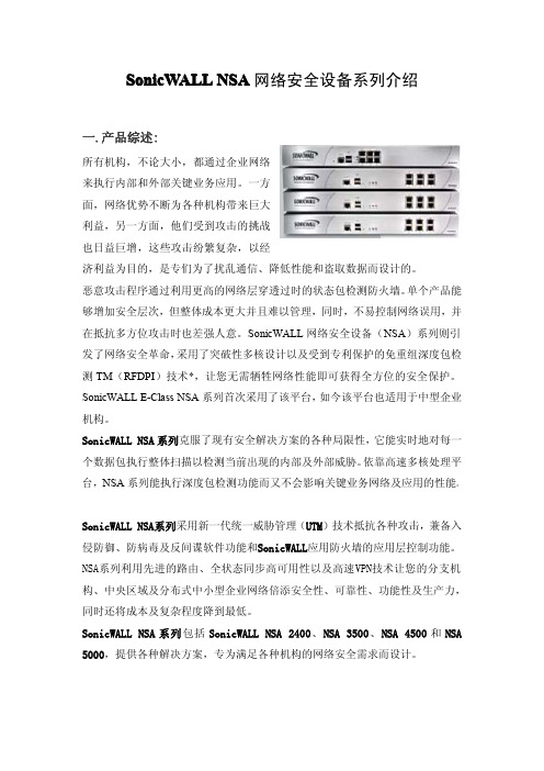
二.功能及优点:
SonicWALL NSA 系列新一代安全产品结合了更高层次的 UTM 技术, 集成了入侵防 御、 网关防病毒及反间谍软件以及应用防火墙可配置工具套件, 以防止数据泄漏 以及提供细粒度应用控制。 可扩展多核硬件及免重组深度包检测扫描并清除任意大小文件中的威胁, 对并发 连接没有限制而且网速不减。 SonicWALL NSA 系列采用 SonicOS 5.0 增强版操作系统。 在 SonicOS 5.0 增强版 中的全状态同步高可用性及负载均衡功能可充分利用网络带宽, 保证最大的网络 正常运行时间, 让您随时能访问关键业务资源并且确保 VPN 隧道及其它网络流量 在故障切换时不会中断。 先进的尖端科技和性能以及更低的总拥有成本通过同 时使用多核处理能力而实现, 极大地增加了吞吐量和并行检测能力, 同时降低了 功耗。 先进的路由服务及网络功能结合了先进的网络安全技术,包括802.1q VLAN、 WAN/WAN容 错功能、基于域和对象的管理、负载均衡、先进的NAT模式及更多技术,为您供 供灵活的细粒度配置及全面的安全防护能力。 标准VoIP功能为VoIP基础架构的每一个单元,从通信设备到适用于VoIP的 设 备 , 如SIP Proxies、H.323 Gatekeepers以及Call Server,提供最高级别的安全保 护。 安全的分布式无线LAN服务让设备能够起到安全无线交换机及控制器的作用,它 能够自动侦别并配置SonicPointsTM,SonicWALL无线访问点保障了分布式网络环 境中的远程访问安全。 联网服务质量(QoS)特性利用行业标准的802.1p及差异化服务编码点(DSCP) 服务类别(CoS)指示符提供强大灵活的带宽管理,这对VoIP、多媒体内容及关 键业务应用起到至关重要的作用
五.主要功能模块:
电源模块常见异常和解决方法 -回复
电源模块常见异常和解决方法-回复电源模块是电子设备中不可或缺的一部分,用于将交流电源转换成电子设备所需的直流电源,同时还能对电压进行稳定、过载和短路保护。
然而,由于使用环境、设计问题或是其他原因,电源模块可能会出现一些常见的异常情况。
以下将一一介绍这些常见异常及解决方法。
1. 过热过热是电源模块常见的故障之一。
主要原因可能是环境温度过高、通风不畅或负载过重。
解决方法如下:- 检查是否有堵塞在电源模块周围的物体,保证通风良好;- 定期清洁电源模块,尤其是散热风扇;- 如果经常性地工作在高温环境下,考虑使用具有更好散热性能的电源模块;- 若负载过重,将负载均衡,或添加一个额外的电源模块。
2. 过载保护电源模块具有过载保护功能,当负载超过额定功率时,电源模块会自动关闭。
以下是解决方法:- 检查所接的负载是否超过了电源模块的额定功率;- 检查所接的负载是否存在突然的大功率需求;- 调整负载的功率,以确保不超过电源模块的额定功率。
3. 短路保护电源模块会自动保护电源模块和负载免受电路短路带来的损坏。
以下是解决方法:- 检查负载线路,是否存在短路情况;- 如果电源线路过长,考虑缩短电源线;- 使用负载电路保护装置,如保险丝或断路器。
4. 输出电压不稳定当电源模块的输出电压不稳定时,可能会影响到正常工作的设备。
解决方法如下:- 检查输入电源线路,确保输入电压稳定;- 检查负载电路,确保负载电阻匹配;- 检查电源模块的调节电路,如稳压器;- 考虑更换电源模块,以确保输出电压稳定。
5. 电源噪声电源噪声会对设备的正常工作和信号传输造成干扰。
解决方法如下:- 检查电源模块的滤波电容,确保其工作正常;- 添加额外的滤波电容或滤波电感,以减小电源噪声;- 使用线性电源模块代替开关电源模块,以降低电源噪声。
除了上述几种常见异常情况,电源模块还可能遇到其他问题,如电源线松动、电源启动困难等。
对于这些问题的解决,可以采取修复或替换的方式,或者联系专业人员进行维修。
多路电源模块组件-概述说明以及解释

多路电源模块组件-概述说明以及解释1.引言1.1 概述多路电源模块是一种重要的电力管理装置,用于为电子设备提供稳定可靠的电源供应。
随着电子设备的发展,对电源供应的要求也越来越高,特别是在多路电源切换和保护方面。
多路电源模块通过集成多个电源输入通道和相应的电源管理电路,实现对多种电源的切换和监控,为电子设备提供持续稳定的电能。
它具有灵活性高、效率高、可靠性强等特点,广泛应用于各种领域。
本文将首先介绍多路电源模块的定义和特点,包括其构成要素、工作原理和关键技术。
然后,将探讨多路电源模块在各种应用场景中的具体应用,如医疗设备、工业自动化、通信设备等。
通过分析和比较,将阐述多路电源模块在不同应用场景下的优势和适用性。
最后,本文将总结多路电源模块的优势和不足之处,并对其未来发展进行展望。
希望通过本文的阐述,能够深入了解多路电源模块的重要性和应用前景,为相关领域的研究和应用提供参考和借鉴。
1.2 文章结构本文将围绕多路电源模块组件展开,分为引言、正文和结论三个部分。
引言部分将对多路电源模块进行概述,介绍其定义和特点,并说明撰写本文的目的。
正文部分将深入探讨多路电源模块的应用场景,包括但不限于个人电子设备、工业自动化设备等领域,以及在不同环境下的应用案例。
通过对多路电源模块的详细分析,读者将能够更好地理解其工作原理、优势和不足,以及如何选择适合的多路电源模块。
结论部分将对多路电源模块的优势和不足进行总结,探讨其未来可能的发展方向。
同时,本节将回顾并强调文章的重点和亮点,以便读者能够更好地领会多路电源模块在电子设备领域的重要性和前景。
1.3 目的在本文中,我旨在介绍多路电源模块组件的相关知识和应用场景。
多路电源模块是一种能够同时提供多个电源输出的模块,它能方便地为各种电子设备提供电力支持。
本文的目的主要包括以下几点:首先,我们将概述多路电源模块的定义和特点。
通过对多路电源模块的功能、工作原理和技术指标进行介绍,读者将能够更好地了解多路电源模块的基本概念和特性。
电源模块的主要用途

电源模块的主要用途电源模块是电子设备中的一个重要组成部分,其主要作用是将电源输入转化为稳定可靠的电源输出,为其他电子器件提供所需的电能。
电源模块广泛应用于各种电子设备中,例如计算机、通信设备、工控设备、家电产品等等。
首先,电源模块可以起到电能转换的作用。
电源模块可以将交流电源转化为所需的直流电源或其他形式的电源。
由于大多数电子设备需要直流电源来供电,电源模块可以将交流电(AC)转换为直流电(DC)以满足设备的使用要求。
它可以通过整流和滤波等技术将交流电转换为稳定的直流电,以供电子设备使用。
其次,电源模块还可以提供稳定可靠的电源输出。
电子设备对电能的质量要求很高,特别是对电压和电流的稳定性有严格要求。
电源模块可以通过采用稳压、稳流等技术来保证电源输出的稳定性和可靠性,从而确保供电设备正常工作。
它可以通过电压调整、过载保护、短路保护等功能来保护设备和电源模块本身免受电力问题的影响。
此外,电源模块还可以提供各种不同电源输出形式。
除了直流电,电源模块还可以提供不同电压、电流和功率等多种规格的电源输出。
例如,一些设备需要低压直流电,如5V、12V等,而其他设备可能需要高压直流电,如24V、48V等。
电源模块可以根据不同设备的需求提供不同类型的电源输出,以满足不同设备的使用要求。
此外,电源模块还可以实现电源管理功能。
电源模块可以监测和管理输入和输出电源的状态,包括电压、电流、功率等参数,并根据需要进行调整和控制。
例如,当设备需要更高的电源功率时,电源模块可以自动增加输出电压和电流来满足设备的需求;当设备处于待机状态时,电源模块可以自动降低输出电源的功率,以节省能源。
通过电源管理功能,电源模块可以提高设备的能效和节能性能。
最后,电源模块还可以提供电源的保护功能。
电子设备在使用过程中常常面临各种潜在的电力问题,如电压过高、过低、瞬时电压波动、电流突变等。
这些电力问题可能对设备的正常运行和使用产生不利影响。
电源模块可以通过采取过压保护、过流保护、过载保护等技术手段来保护设备免受这些电力问题的伤害,提供可靠的电源供应。
dcdc电源模块标准

DC-DC电源模块的标准通常包括以下几个方面:
输入和输出电压范围:标准规定了DC-DC电源模块的输入和输出电压范围,以确保模块的安全和正常运行。
输出功率和电流:标准规定了DC-DC电源模块的输出功率和电流的最大值,以确保模块能够满足特定应用的需求。
效率和效能:标准规定了DC-DC电源模块的效率和效能要求,以确保模块能够提供高效的能量转换和稳定的输出。
电气特性:标准规定了DC-DC电源模块的输入和输出的电气特性,如稳定性、波动性、纹波噪声等,以确保模块的电气性能满足应用要求。
安全性和可靠性:标准规定了DC-DC电源模块的安全性和可靠性的要求,包括过压保护、过流保护、短路保护、过温保护等,以确保模块在各种工作环境和异常情况下的安全和可靠性。
尺寸和外观:标准规定了DC-DC电源模块的尺寸和外观要求,以确保模块能够符合特定应用的安装和布局需求。
DC-DC电源模块的标准通常由相关的行业组织或标准化机构制定,如国际电工委员会(IEC),美国电子工程师协会(IEEE),中国电子技术标准化研究院(CESI)等。
具体的标准可以根据应用领域和具体需求进行选择和参考。
避免dc-dc电源输出端带大电容满载启动时发生过流保护的方法
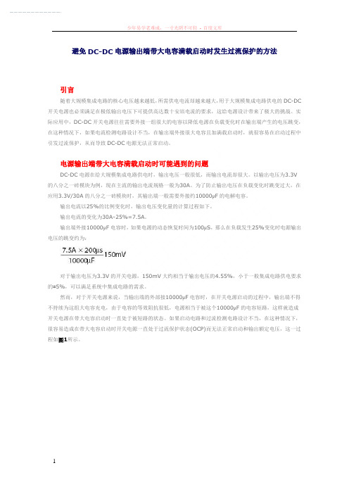
避免DC-DC电源输出端带大电容满载启动时发生过流保护的方法引言随着大规模集成电路的核心电压越来越低,所需供电电流却越来越大,用于大规模集成电路供电的DC-DC 开关电源也必须满足在极低输出电压下可提供高达数十安培电流的要求,这给电源设计带来了极大的挑战。
实际应用中,DC-DC开关电源往往需要外接一组很大的电容以降低电源在负载变化时在输出端产生的电压跳变,在这种情况下,如果电流检测电路设计不当,在输出端外接很大电容且加满载启动时,就很容易在启动过程中引发过流保护,从而导致DC-DC电源无法正常启动。
电源输出端带大电容满载启动时可能遇到的问题DC-DC电源在给大规模集成电路供电时,输出电压一般很低,而输出电流却很大。
以输出电压为3.3V的八分之一砖模块为例,现在主流的输出电流规格一般为30A。
为了防止输出电压在负载变化时跳变过大,在应用3.3V/30A的八分之一砖模块时,其输出端一般需要外接约10000μF的电解电容。
输出电流以25%的比例变化时,输出电压变化量的计算过程如下。
输出电流的变化为30A×25%=7.5A。
输出端外接10000μF电容时,如果电源的动态恢复时间为100μS,那么在负载发生25%变化时电源输出电压的跳变约为:对于输出电压为3.3V的开关电源,150mV大约相当于输出电压的4.55%,小于一般集成电路供电要求的±5%,可以满足系统中集成电路的需求。
然而,对于开关电源来说,当输出端的外部接10000μF电容时,在开关电源启动的过程中,输出端不得不持续为这组大电容充电,由于电容的等效阻抗很低,电源相当于被这个10000μF的电容短路,这样就造成开关电源在带大电容启动时一直处于被短路的状态。
如果启动电路和过流检测电路设计不当,在这种情况下,很容易造成在带大电容启动时开关电源一直处于过流保护状态(OCP)而无法正常启动和输出额定电压,这一过程如图1所示。
图1 电源输出端带大电容满载启动时出现过流保护现象的曲线在图中,Channel 2显示的是电源模块在输出端带大电容满载启动时的过流检测信号的幅度。
- 1、下载文档前请自行甄别文档内容的完整性,平台不提供额外的编辑、内容补充、找答案等附加服务。
- 2、"仅部分预览"的文档,不可在线预览部分如存在完整性等问题,可反馈申请退款(可完整预览的文档不适用该条件!)。
- 3、如文档侵犯您的权益,请联系客服反馈,我们会尽快为您处理(人工客服工作时间:9:00-18:30)。
Load-sharing techniques:Paralleling power modules with overcurrent protectionParalleling low-current, low-voltage power modules for high-current, low-voltage applications has many benefits.Among them are: redundancy for enhanced reliability, hot-swap capability, distributed heat removal, and design flexi-bility. Paralleling power stages requires load sharing in order to equalize the stresses among the modules. One method of load sharing, based upon the automatic master/slave architecture, is to use a dedicated controller, such as the UCC39002, to provide for equal current distribution of the load current among the parallel-connected power sup-plies. The power modules must be equipped with true remote-sense capability or an output-adjustment terminal.The output current of each module is measured and com-pared to a common load-share bus. The positive sense voltage or the voltage of the output voltage adjust pin of each module is adjusted to provide equal current sharing.Several modules are paralleled so that the entire assem-bly can support a full load much greater than an individual module would be capable of supplying. Due to manufactur-ing tolerances and component variations, startup delay times typically vary slightly from module to module. When the modules to be paralleled have an overcurrent protection circuit featuring constant current limit with automaticrecovery, starting up fully enabled into the full system load does not pose a problem. Inevitably, one module will haveTexas Instruments Incorporated Power ManagementBy Lisa Dinwoodie (Email: lisa_dinwoodie@)Power Applications Specialista faster turn-on than the others. The eager module will carry as much of the load as it can, sometimes up to 140%of its individual current capacity, before its output voltage falters. Meanwhile, the next module will come up and con-tribute to the load. After a brief transition time, all of the modules will be up, the master will be recognized, and accurate load sharing will take place.When the modules to be paralleled have an overcurrent protection circuit featuring a hiccup mode, starting up fully enabled into full system load, regardless of the load sharing technique used, does pose a problem. The module with the fastest turn-on profile will come up into an overcurrent condition. Immediately, in an act of self-preservation, it will go into hiccup mode, alternately sinking and sourcing current. The next module to come up into the load will also fall into this hiccup mode, sinking current when the other module sources it. Because the load-share circuitry essentially adds a voltage loop to the output of each mod-ule, this hiccupping overcurrent protection mode will prevent loop closure. Simultaneously enabling the modules will prevent this hiccup mode from starting, and load shar-ing can be successfully achieved.Figure 1 shows a simple comparator circuit that will simultaneously enable two modules and can be expanded to accommodate more if needed. It assumes that the onlyTexas Instruments IncorporatedPower Managementbias available for the logic gates is the 48-Vdc bus used as the input to the modules themselves. The circuit is designed to short the modules’ on/off pins to ground simultaneously when their inputs reach 35 V, assuming that the modules’input range is between 36 V and 75 V and that they have a turn-on threshold of approximately 33 V.The PNP transistor, Q1, its emitter and base resistors,and the two 15-V Zener diodes provide a 15-V, 5-mA bias to the comparators and the NAND gate from the input line, which could vary from 36 Vdc to 75 Vdc. The TL431is set up to provide a regulated 10-V reference voltage for the inverted comparator inputs. The non-inverted com-parator input signals are derived from resistively dividing the input voltages of the modules. Because the bias andcomparator signals are from the same source, capacitors are needed to delay the comparator input signals long enough so that the LM393, U 2, is operational and “smart.”This circuit is added to the load-share board and success-fully turns on the modules simultaneously into a full system load without triggering the overcurrent hiccup mode of the modules.Related Web sites/sc/device/partnumberReplace partnumber with LM393, SN74AHC1G00, TL431or UCC39002IMPORTANT NOTICETexas Instruments Incorporated and its subsidiaries (TI) reserve the right to make corrections, modifications, enhancements, improvements, and other changes to its products and services at any time and to discontinue any product or service without notice. Customers should obtain the latest relevant information before placing orders and should verify that such information is current and complete. All products are sold subject to TI's terms and conditions of sale supplied at the time of order acknowledgment. TI warrants performance of its hardware products to the specifications applicable at the time of sale in accordance with TI's standard warranty. Testing and other quality control techniques are used to the extent TI deems necessary to support this warranty. Except where mandated by government requirements, testing of all parameters of each product is not necessarily performed.TI assumes no liability for applications assistance or customer product design. Customers are responsible for their products and applications using TI components. To minimize the risks associated with customer products and applications, customers should provide adequate design and operating safeguards.TI does not warrant or represent that any license, either express or implied, is granted under any TI patent right, copyright, mask work right, or other TI intellectual property right relating to any combination, machine, or process in which TI products or services are used. Information published by TI regarding third-party products or services does not constitute a license from TI to use such products or services or a warranty or endorsement thereof. Use of such information may require a license from a third party under the patents or other intellectual property of the third party, or a license from TI under the patents or other intellectual property of TI. Reproduction of information in TI data books or data sheets is permissible only if reproduction is without alteration and is accompanied by all associated warranties, conditions, limitations, and notices. Reproduction of this information with alteration is an unfair and deceptive business practice. TI is not responsible or liable for such altered documentation.Resale of TI products or services with statements different from or beyond the parameters stated by TI for that product or service voids all express and any implied warranties for the associated TI product or service and is an unfair and deceptive business practice. TI is not responsible or liable for any such statements. Following are URLs where you can obtain information on other Texas Instruments products and application solutions: TI Worldwide Technical Support InternetTI Semiconductor Product Information Center Home PageTI Semiconductor KnowledgeBase Home Page/sc/knowledgebaseProduct Information CentersAmericasPhone+1(972) 644-5580Fax+1(972) 927-6377 Internet/Email /sc/pic/americas.htmEurope, Middle East, and AfricaPhoneBelgium (English)+32 (0) 27 45 54 32Netherlands (English)+31 (0) 546 87 95 45 Finland (English)+358 (0) 9 25173948Russia+7 (0) 95 7850415 France+33 (0) 1 30 70 11 64Spain+34 902 35 40 28 Germany+49 (0) 8161 80 33 11Sweden (English)+46 (0) 8587 555 22 Israel (English)1800 949 0107United Kingdom+44 (0) 1604 66 33 99 Italy800 79 11 37Fax+(49) (0) 8161 80 2045Internet /sc/pic/euro.htmJapanFaxInternational+81-3-3344-5317Domestic0120-81-0036 Internet/EmailInternational /sc/pic/japan.htmDomestic www.tij.co.jp/picAsiaPhoneInternational+886-2-23786800Domestic Toll-Free Number Toll-Free Number Australia1-800-999-084New Zealand0800-446-934China800-820-8682Philippines1-800-765-7404 Hong Kong800-96-5941Singapore800-886-1028Indonesia001-803-8861-1006Taiwan0800-006800Korea080-551-2804Thailand001-800-886-0010 Malaysia1-800-80-3973Fax886-2-2378-6808Email tiasia@ Internet /sc/pic/asia.htm ti-china@C011905 Safe Harbor Statement:This publication may contain forward-looking statements that involve a number of risks and uncertainties. These “forward-looking statements” are intended to qualify for the safe harbor from liability established by the Private Securities Litigation Reform Act of 1995. These forward-looking statements generally can be identified by phrases such as TI or its management “believes,” “expects,” “anticipates,”“foresees,” “forecasts,” “estimates” or other words or phrases of similar import. Similarly, such statements herein that describe the company's products, business strategy, outlook, objectives, plans, intentions or goals also are forward-looking statements. All such forward-looking statements are subject to certain risks and uncertainties that could cause actual results to differ materially from those in forward-looking statements. Please refer to TI's most recent Form 10-K for more information on the risks and uncertainties that could materially affect future results of operations. We disclaim any intention or obligation to update any forward-looking statements as a result of developments occurring after the date of this publication.Trademarks: All trademarks are the property of theirrespective owners.Mailing Address: Texas InstrumentsPost Office Box 655303Dallas, Texas 75265© 2005 Texas Instruments IncorporatedSLYT100。