单片机应用技术教案双语教学3Ch3InstructionSystemoftheMCS51
《单片机原理与应用》双语课程的教学探索
《单片机原理与应用》双语课程的教学探索单片机技术是电子信息类专业不可或缺的重要技术之一。
在传统单片机课程教学中,通常采用讲授理论知识和实验演示相结合的方式,但这种传统的教学方式存在一些问题,如学生缺乏实际操作经验、理论与实践脱节、教学内容单调枯燥等,影响了教学效果和学生学习兴趣。
因此,如何创新单片机课程教学方式,提高教学效果是一个亟待解决的问题。
本文以《单片机原理与应用》双语课程为例,探索一种创新的单片机课程教学方式。
这门课程主要面向电子信息工程和自动化等相关专业的学生,涵盖单片机的基本原理、应用及其相应的编程技术。
教学目标的确定教学目标是教学设计和实施的基础和核心,本课程的教学目标主要如下:1、了解单片机的基本原理和体系结构;2、掌握单片机编程基础知识和常见编程技术;3、熟练掌握单片机的应用技术和相关电路设计;4、能够设计并实现基于单片机的实际工程项目。
教学方式的创新为了达到上述教学目标,我们采用了如下教学方法:1、实验为主的教学方式。
课程设置了大量的实验项目,通过实验演示和实践操作,使学生全面掌握单片机的基本原理和编程技术。
2、项目驱动式教学方法。
课程设计了一些实际的单片机项目,如温湿度测量、智能小车、遥控器等,并引导学生在项目中探索学习。
3、互动式教学形式。
利用互联网技术,采用在线答疑、讨论、群组分享等互动形式,促进学生间的交流与互动,提高教学效果。
4、双语教学方式。
本课程采用英语双语教学方式,使学生能在多语言环境中学习单片机技术,提高学生的英语水平和专业能力。
教学效果的评估为了检验新教学方式的教学效果,我们通过问卷调查和实验表现等多种方式进行了评估,评估结果表明:1、多数学生对新教学方式表示肯定,认为实验为主、项目驱动、互动式教学更加容易理解和记忆。
2、多数学生表示,《单片机原理与应用》双语课程让他们的英语水平得到了提高。
3、评估结果表明,通过新教学方式,学生成绩明显提高,对课程内容的掌握度和应用水平都有了明显提高。
《单片机原理与应用》双语课程的教学探索

《单片机原理与应用》双语课程的教学探索随着我国电子信息技术的不断进步,单片机技术的应用越来越广泛,成为电子信息技术领域中的一个重要组成部分。
因此,单片机技术的教学也是电子信息类专业重要的课程之一,对学生的综合素质和实践能力有着重要的影响。
在单片机教学中,传统的黑板讲解和实验课程已经不能满足学生对单片机技术的需求,需要更加灵活多样的教学方式。
本文探讨了一种双语(中英文)课程的教学模式,以期提高学生英语技能及单片机相关知识的学习效果。
1.设计课程大纲在双语课程设计中,应结合学生的实际情况和学科特点,制定完整的课程大纲,包括课程的目标、每章目的和内容、课程安排、考核方式等内容。
课程的目标是指通过双语教学方式,使学生掌握单片机的基本理论和应用技术,熟悉单片机常用模块和器件的使用方法,提高学生英语阅读和交流能力,培养学生的实践操作能力。
课程内容包括单片机的基本原理、编程技术、常用模块和器件的使用方法等,并增加一些实际应用案例,使学生更好地理解单片机技术的实际应用。
2.探索双语教学的方式双语课程的教学方式应该以理论讲解和实践操作相结合为主,增加常用模块和器件的实际应用案例,激发学生的兴趣。
在教学中,可以采用双语教学模式,即用中文和英文相结合的方式来讲解单片机的相关知识。
在讲解过程中,需要注意用与学生目前所学知识相适应的英语授课和用中文进行适当解释,以便学生更好地理解和掌握所讲知识。
另外,还可增加一些双语阅读材料,培养学生的英语阅读能力。
为了更好地培养学生的动手实践能力,可采用坊间流行的硬件板组装测试方法。
学生组装好后,进行编程操作,以检测组装结果和编程技巧,同时培养学生团队合作能力。
3.考试并评估为了能够客观地了解学生的学习情况,考核方式也需要做相应的调整。
一般来说,单片机教学中考试是必不可少的一环。
在双语课程中,测试的内容也需要增加英语阅读和交流的考查成分,以综合评估学生的英语能力。
此外,还需对学生的实践操作能力进行考查,以确定学生的技能是否达到教学目标。
《单片机原理及应用I》教学大纲英文
The Teaching Outline of the Principle andApplication of MCUCourse name: The principle and Application of MCUCourse Number: 02323030 Course period: 40 ( experiment 10) Credit: 2.5Applied major: Electronic engineering, Electronic science and technology, Communication engineeringⅠ. The status, mission and function of the courseThe embedded system can be seen everywhere in our daily life. MCU is the lower part of the embedded system and it has been widely used in measurement and control area. In this course,MCS-51 is the core of system. The student should know the basic structure and principle, instruction system, expansion of hardware system. Also the combination of hardware and software should be known. All these method should be applied in practice primarily. Form the course, the student should know the basic knowledge and skill of MCU application, the electronic design and be adaptive to the demand of the modern society.Ⅱ. The relative coursePre-course: digital electronics, analog electronics, The principle and application of the computerBack-course: The principle and technology of sensor, Intelligent InstrumentⅢ. The basic content and requirement of the courseChapter 1 IntroductionContent: This chapter introduces the basic character and application of microcontroller unit.Requirement: The basic concept and familiar brand of MCU should be known.Chapter 2 The structure of MCS-51Content: This chapter introduces the internal structure which includes the structure of CPU and memory, I/O ports, timer/counter, interrupt system, also the pins function and working mode should be known.Requirement: The internal resource should be grasped skillfully. The student should be familiar with the internal structure of MCU, and have the hardware basis for the future chapters.Chapter 3 The instruction system of MCS-51Content: This chapter introduces the instruction format, addressing mode and instruction system of MCS-51Requirement: The function and application characteristic of instructions should be graspedskillfully, and the students should know that the instruction system and the internal resources are related tightly, and the student can read and write easy program.Chapter 4 Assembly program designContent: This chapter introduces the characteristic of the machine language, assembly language, advanced language, the programming of assembly language such as the subroutine program, searching table, the keyword searching, the maxim and minimum number searching, the sequence of numbers, program branching, circulation and code changing of subroutine.Requirement: The students should be familiar with assembly language of MCS-51 to program all kinds of subroutine, because it is the fundamental of the program design. To make the students grasp the contents of the chapter, some experiment lessons should be set.Chapter 5 Interrupts system of MCS-51Content: This chapter introduces the principle of the interrupt system, some related SFRs and application examples.Requirement: The interrupt resources of MCS-51, how to initial the related SFR and how to program the interrupt subroutine are especially focused.Chapter 6 The timers and counters of MCS-51Content: This chapter introduces the structure and principle of timers and counters, some related SFRs and application examples.Requirement: The working mode of timers/counters, external circuits design relating the interrupt and timer/counter the are especially focused.Chapter 7 The serial port of MCS-51Content: This chapter introduces the structure and principle of the serial port, some related SFRs and application examplesRequirement: The basic concept of serial communication, the basic resource of serial I/O ports should be grasped skillfully. Some easy serial communication program should be read and written.Chapter 8 The external expansion of MCS-51Content: This chapter introduces the expansion of external bus, external storages and parallel interface.Requirement: The concept of three buses should be known. The student should be familiar with the representative chips and the combination of MCS-51. Also the serial and parallel ports, the common use of external devices characterize ,the easy external circuits design and software program should be grasped.Ⅳ.The requirement of the experiments and course design1. experiments and demandThe course is focused on practice. The multi-media should be applied in theory teaching, that makes the student sensitive to the MCU application. The demand is as follows: Experiment 1: The basic usage of Keil software and none symbol numbers addition (2 hours, must done, test style)The usage of Keil software should be known primarily. A program of double bytes none symbol numbers addition should be written and debugged. The environment and instruction system should be grasped familiarly.Experiment 2: A binary number changed to a decimal number(2 hours, must done, design style)A program of a binary number changed to a Decimal number should be written, that makes a double bytes binary number changes to a decimal number. And the result should be displayedExperiment 3: Sorting of the data (2 hours, must done, design style)A sorting program should be programmed, that makes a series of numbers in the RAM sort from the least to the most.Experiment 4: LED displaying (2 hours, must done, design style)The displaying principle of LED, the implement of serial method of LED and the combination debugging of the software and hardware should be known.Experiment 5: The experiment of Times (2 hours, must done, comprehensive style)A software of interrupt program using Timer 0 should be written, that makes the counter increase 1 per-second and display in the LED.Experiment 6: Data communication based on RS232(2 hours, selected done, test style)A communication program between MCU and pc should be written to fulfill follows:1.The lower-part transmits data to the upper-part, if it is correct, the upper-part sends back true message, otherwise sends back wrong message.2. The upper-part transmits data to the lower-part, if it is correct, the lower-part sends back true message and displays data in LED, otherwise sends back wrong message and display DP51 in LED.Experiment 7: Simulation of the neon-light (2 hours, selected done, design style)Assembly language should be written to make LEDs on the circuit board simulate the neon-light.Experiment 8: Keys identification (2 hours, selected done, comprehensive style)A program should be written to recognize 8 keys, give the relative key-words and displays it in LED.(1) An automatic traffic light system based on MCS-51An automatic traffic light system should be designed using MCS-51 to fulfill the connect and disconnect time, switching between day and night and display the counter down time.(2)Digital clock based on MCS-51A minimum system of MCS-51 should be written to fulfill the basic function of the time, the clock time, second time, make deepen understanding of external devices such as keyboards and LED, upgrade the usage of timers and interrupt.Ⅴ.The quantities and demand of exercisesIn each chapter, some exercises are given to consolidate the basic concept, enhance the practice skill about the principle, hardware design and programming.Ⅵ.Teaching and testing styleThe blackboard and multimedia are used in teaching lesson. The most-significant part is in teaching lesson, also the testing and designing experiment is combined. The testing style combine the final test and peacetime test which includes exercise and fulfillment of experiment.Ⅶ.The assignment of teaching hours1.The focus and difficulty of the course: There are some difficulties in the course such as the internal sources, the instruction system, the program design, the characteristics and application of external devices. The combination and repeating should be applied between the front and back parts which make the student have deepen understanding about the basic concept. Because the course is practical, there are many codes and hardware circuit diagram, multimedia is introduce the teaching with some necessary writing on the blackboard. After the basic concept is given, new method should be complemented to widen the information for the technology is developing rapidly,The course is the testing course of bi-languages, two teaching materials are used, one is Chinese, the second is English written by ourselves. Two materials should be both read to cultivate the professional English skill. Chinese and English should be used in class, particularly in internal-resources, instruction set, the IDE software and chips datasheet, English is focused, which make the student know the datasheet content, use the software of English, know the menu, dialog box and help. Some English exercise is required to cultivated the comprehensive ability of lessoning, speaking, reading and writing using professional English.2.Recommend books(1) Hu hancai. The principal and interface technology (2nd edition ). Tsinghua publishing company, 2004(2)Li guangdi. The basis of single chip microcomputer(revised edition) BUAA publishing company, 2001(3) Bi-languages material written by ourselves3. Main references(1) MCS51 MICROCONTROLLER FAMILY USER’S MANUAL(2)He liming Selected material about the application technology of MCU(1-8). BUAA publishing company, 1999。
《单片机原理与应用》双语课程的教学探索
《单片机原理与应用》双语课程的教学探索随着科技的飞速发展,单片机已经成为了现代电子技术领域不可或缺的一部分。
《单片机原理与应用》课程作为电子信息类专业的重要课程之一,对学生进行单片机的基本原理和应用进行系统的讲解,培养学生对单片机技术的理解和应用能力。
而在当前国际化越来越受重视的背景下,双语教学模式已经成为了高校教育的一个新趋势。
本文将探索如何结合双语教学模式,提高《单片机原理与应用》课程的教学质量。
1. 提高学生的英语水平。
随着国际化的发展,英语已经成为了国际间交流的重要语言。
通过在《单片机原理与应用》课程中引入英语教学,可以提高学生的英语听说读写能力,增强其国际竞争力。
2. 拓宽知识视野。
单片机技术是一个国际性的学科,国外学者在这一领域的研究成果丰富。
通过双语教学模式,可以让学生接触到更多国外的优秀教材和学术资源,开阔其学术视野。
3. 增强学生的综合能力。
双语教学要求学生在理解和掌握专业知识的还要应对另一种语言的学习,这样可以提高学生的学习能力和应变能力。
二、双语教学在《单片机原理与应用》课程中的具体实施方式1. 采用双语教材。
为了实现双语教学的目标,需要有丰富的双语教材支持。
教师可以引入一些国外优秀的单片机教材作为辅助教材,为学生提供更广泛的学习资源。
2. 引入双语教学视频。
通过引入一些国外的单片机教学视频,可以帮助学生更直观地了解单片机原理和应用,同时也可以锻炼他们的英语听力和口语能力。
3. 实施双语教学模式。
在课堂教学中,可以采用中英文交替的方式进行教学,让学生在学习专业知识的也能提高英语的听说读写能力。
4. 开展双语教学实践活动。
可以组织学生参加一些国际性的单片机比赛或学术交流活动,让他们在实践中提高英语交流能力,同时也加深对单片机技术的理解和应用。
1. 学生英语水平的提高。
通过课程学习和实践活动的组织,可以对学生的英语水平进行定期的评估,了解其英语听说读写能力的提高情况。
2. 学生对单片机技术的理解和应用能力。
《单片机原理与应用》双语课程的教学探索
《单片机原理与应用》双语课程的教学探索《单片机原理与应用》是计算机、电子、通信等相关专业的一门重要课程,通过学习这门课程,学生可以了解单片机的基本原理、应用和设计方法,掌握单片机的编程技术和开发应用。
为了提高教学效果,我们对《单片机原理与应用》课程进行了教学探索,采用双语教学的方式,为学生提供更加全面和深入的学习体验。
双语教学是指教师在授课过程中既使用学生所使用的语言,又用一种外语进行授课。
单片机原理与应用这门课程,通常采用英文教材,而学生的英文水平参差不齐。
我们通过双语教学的方式,满足了学生在专业知识学习的同时提高英语能力的需求。
我们在课程设置上进行了调整,将部分课程内容以双语教学进行。
对于单片机的基本原理和结构,我们利用中文进行讲解,帮助学生理解和掌握知识点;而对于单片机的编程操作、实验设计等内容,我们采用英文进行讲解,帮助学生提高英语听说能力。
通过这样的设置,学生既可以理解专业知识,又可以提高英语水平,达到了双赢的效果。
我们在教学方法上进行了改进,注重学生的参与和互动。
在课堂上,我们鼓励学生用英文提问和回答问题,通过讨论和交流,帮助学生运用英文进行表达和沟通。
我们也设置了一些小组活动和实验操作,让学生在实际操作中用英文进行指导和交流,锻炼他们的英语技能。
通过这样的教学方法,学生的学习主动性和参与度得到了提升,英语能力也得到了锻炼和提高。
我们还通过多种途径进行教学辅助,帮助学生更好地学习和掌握知识。
我们录制了一些英文教学视频,让学生可以在课后复习英文讲解的内容,加深理解和记忆。
我们还利用英文教材中的案例和实例,让学生在课堂上进行分析和讨论,帮助他们更好地理解专业知识。
我们还鼓励学生通过英文文献和资料进行学习和研究,培养他们的自主学习能力。
通过这些教学辅助的手段,学生的英语学习得到了更多的支持和帮助。
通过对《单片机原理与应用》课程的双语教学探索,我们发现学生的学习兴趣和学习效果都得到了显著提高。
《单片机原理与应用》双语课程的教学探索
《单片机原理与应用》双语课程的教学探索随着信息技术的不断进步和发展,单片机在各个领域的应用越来越广泛,受到越来越多人的关注和学习。
为了满足不同层次和需求的学生的学习需要,我们开设了《单片机原理与应用》双语课程,通过将中文和英文教学相结合,向学生传授单片机的原理和应用知识,同时提高学生的英语水平。
我们在教学内容的选择上注重理论与实践的结合,力求教学内容既具有深度又具有广度。
在单片机的原理方面,我们通过讲解基本原理和逻辑设计、存储器和输入输出设备的原理等内容,帮助学生理解单片机的工作原理和内部结构。
在单片机的应用方面,我们通过讲解数字电子技术、模拟电子技术和通信技术在单片机中的应用,帮助学生了解单片机在各个领域的应用情况。
我们在教学方法的选择上注重启发式教学和实践教学相结合。
在启发式教学方面,我们通过引导学生提出问题、探索问题解决方法和激发学生学习兴趣的方式,培养学生的创新思维和问题解决能力。
在实践教学方面,我们通过实验、项目和案例分析等方式,帮助学生将理论知识应用到实际中去,并培养学生的动手能力和实践能力。
我们在教学资源的选择上注重中外文教材和网络资源的结合,提供多样化、全方位的学习资源。
我们选用中外文教材,既可以满足学生对中文教材的需求,也可以提供英文学习的机会,帮助学生提高英语水平。
我们还鼓励学生利用网络资源,参与在线讨论、查找相关资料和学习案例,拓宽学习视野,加深对单片机的理解和应用。
我们在评价方式的选择上注重综合评价和能力评价相结合,注重学生的实际能力和综合素质的培养。
我们通过课堂考试、实验报告、项目评估等方式,全面考察学生在知识、实践和创新能力等方面的表现,帮助学生发现自身的优势和不足,进一步提高学习效果和能力水平。
《单片机原理与应用》双语课程的教学探索旨在通过中英文教学相结合、理论与实践相结合、启发式教学和实践教学相结合、中外文教材和网络资源相结合、综合评价和能力评价相结合等多重方式,提高学生对单片机原理和应用的理解和掌握,培养学生的创新思维、问题解决能力和动手能力,促进学生综合素质的全面发展。
《单片机原理与应用》双语课程的教学探索
《单片机原理与应用》双语课程的教学探索近年来,计算机技术在各个领域的应用越来越广泛,而单片机作为计算机技术的重要组成部分,也逐渐成为学生学习和研究的重点。
建立一个科学、有效的单片机教学体系对于培养学生的计算机技术水平和创新能力具有重要意义。
《单片机原理与应用》双语课程的教学探索旨在通过提供全英文授课的环境,提升学生的英语听说能力,增强他们在计算机领域的跨文化交流能力。
该课程采用了多种教学方法,如例题演示、实验操作、课堂讨论和小组合作等,使学生能够通过实践掌握单片机的基本原理和应用技术。
在教学内容上,我们注重理论与实践的结合。
通过生动的授课和实验操作,我们引导学生深入理解单片机的工作原理和结构特点,并通过实际应用案例,让学生了解单片机在各个领域的应用,如控制系统、仪器仪表、自动化设备等。
在教学方法上,我们注重启发学生的思维和培养他们的创新能力。
教师在课堂上提出问题,引导学生分析和解决问题,培养他们的问题意识和解决问题的能力。
我们鼓励学生参加科技创新活动和竞赛,提供平台和机会让学生展示和发挥自己的才华和创造力。
在教学评估上,我们注重学生的综合能力培养。
除了传统的考试和作业外,我们还采用项目评估和实践操作的方式进行评估。
通过学生的项目报告和实验成果,我们评估他们的实际操作技能和问题解决能力,以及他们在项目中的团队合作和沟通能力。
通过《单片机原理与应用》双语课程的教学探索,我们发现学生在英语听说能力方面有了明显的提升,并且他们对单片机的理论知识和实际应用有了更深入的了解。
学生的创新能力和团队合作意识也有了明显的提高。
我们也发现一些问题和挑战。
学生对英语的掌握程度有差异,有些学生的英语水平相对较低,需要更多的帮助和指导。
双语课程的教学资源有限,需要进一步完善相关的教材和实验设备。
教师在双语课堂上的教学能力和教学风格需要不断提升和改进,以更好地适应双语教学的需求。
通过《单片机原理与应用》双语课程的教学探索,我们认识到双语教学对于学生的英语能力和计算机技术水平的提升具有重要意义。
单片机原理及应用英文版教学设计 (3)
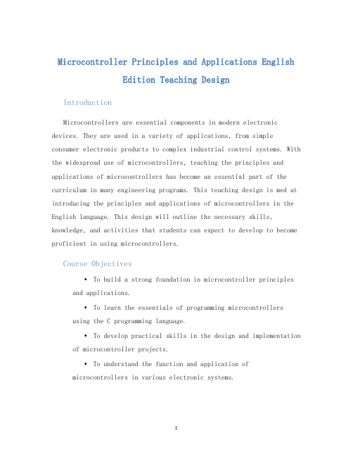
Microcontroller Principles and Applications EnglishEdition Teaching DesignIntroductionMicrocontrollers are essential components in modern electronic devices. They are used in a variety of applications, from simple consumer electronic products to complex industrial control systems. With the widespread use of microcontrollers, teaching the principles and applications of microcontrollers has become an essential part of the curriculum in many engineering programs. This teaching design is med at introducing the principles and applications of microcontrollers in the English language. This design will outline the necessary skills, knowledge, and activities that students can expect to develop to become proficient in using microcontrollers.Course Objectives•To build a strong foundation in microcontroller principles and applications.•To learn the essentials of programming microcontrollers using the C programming language.•To develop practical skills in the design and implementation of microcontroller projects.•To understand the function and application ofmicrocontrollers in various electronic systems.Course OutlineWeek 1: Introduction to Microcontrollers•What are microcontrollers?•Types of microcontrollers•Basic components of a microcontroller system•Microcontroller applicationsActivities: * Microcontroller identification activity * Microcontroller project showcaseWeek 2: C Programming Language•Introduction to the C programming language• C programming basics: data types, variables, operators, and expressions•Using C programming to develop microcontroller applications Activities: * C programming language quiz * Writing basic C programs for microcontrollersWeek 3: Microcontroller Architecture•Microcontroller memory organization•Microcontroller input/output (I/O) interfaces•Microcontroller communication interfaces: SPI, I2C, UART, etc.Activities: * Microcontroller hardware design activity * Microcontroller programming activityWeek 4: Microcontroller Operation•Microcontroller startup and initialization•Microcontroller interrupts and event handling•Microcontroller sleep and power-saving modesActivities: * Writing interrupt handlers for microcontrollers * Microcontroller power-saving modes activityWeek 5: Microcontroller Applications•Embedded system design and development•Real-time control using microcontrollers•Microcontroller-based sensor and actuator control Activities: * Design and implementation of a simple embedded system * Microcontroller-based control of a robot armWeek 6: Microcontroller Project Design•Project proposal development•Project implementation and testing•Project presentation and evaluationActivities: * Microcontroller project design activity * Project proposal presentationConclusionThis teaching design ms to provide students with a comprehensive understanding of the principles and applications of microcontrollers, as well as developing essential practical skills in programming and designing microcontroller projects. The teaching design outlined above can be adapted to meet the specific needs of different institutions and students.。
- 1、下载文档前请自行甄别文档内容的完整性,平台不提供额外的编辑、内容补充、找答案等附加服务。
- 2、"仅部分预览"的文档,不可在线预览部分如存在完整性等问题,可反馈申请退款(可完整预览的文档不适用该条件!)。
- 3、如文档侵犯您的权益,请联系客服反馈,我们会尽快为您处理(人工客服工作时间:9:00-18:30)。
Keywords:MCS(Micro Computer System)指令系统(Instruction System)寻址方式(Look for address mode)寄存器(Register)直接(Directness)位(Bit)立即(Immediately)间接(Indirectly)变址(Change address)相对(Comparatively)数据传送指令(Data Move Instruction)算术运算指令(Arithmetic Operation Instruction)逻辑运算指令(Logic Operation Instruction)控制转移指令(Control Transfer Instruction)位操作指令(Bit Operation Instruction)码(BCD,Binary Coded Decimal)加法(ADD,Addition)减法(SUB,Subtration)乘法(MUL,Multiplication)除法(DIV,Divition)数据调整(DA,Data Adjust)加大(INC,Increase)减少(DEC,Decrease)Introduction:(Ⅰ)Addressing modes:8031’s assembly language instruction set consists of an operation mnemonic and zero to three operands separated by commas. In two byte instructions the destination is specified first, and then the source. Byte wide mnemonics like ADD or MOV use the Accumulator as a source operand and also to receive theresult.The 8031 supports five types of addressingmodes:#Register Addressing#Direct Addressing#Register Indirect Addressing#Immediate Addressing#Index Addressing#Change Addressing#Comparatively Addressing*Register Addressing:Register Addressing accesses the eight working registers (R0-R7) of the selected register bank. The least significant three bits of the instruction opcode indicate which register is to be used for the operation. One of the four banks of registers is to be predefined in the PSW before using register addressing instruction. ACC, B, DPTR and CY, (the Boolean Accumulator) can also be addressed in this mode.*Direct Addressing:Direct addressing can access any onchip variables or hardware register. To indicate the address of the location, an additional byte is attached to the opcode. Depending on the highest order bit of the direct address byte one of two physical memory space is selected. When the direct address range is between 0 and 127 (00H - 7FH) one of the 128 low orderonchip RAM location is accessed. All I/O ports, special function, control registers are assigned between 128 and 255 (80H - FFH). When direct addressing indicates any location in this range, corresponding hardware register is accessed. This is the only method available for accessing I/O ports and special function registers.*Register Indirect Addressing:Register indirect addressing uses the contents of either R0 or R1 (in the pre selected register bank) as a address pointer to locate in a 256 byte block (the lower 128 bytes of internal RAM in 8031 or 256 bytes in 8032) or the lower 256 bytes of external data memory. Note that the special function registers are not accessible in this mode. Access to full 64K external data memory address space is indicated by the 16 bit Data Pointer register, DPTR. Execution of PUSH and POP instructions also involve indirect register addressing. The Stack Pointer indicates the correct stack location anywhere in the internal RAM.*Immediate Addressing:When a source operand is a constant rather than a variable, then the constant can be embedded into the instruction itself. This kind of instructions take two bytes and first one specifies the opcode and second byte gives the required constant.*Index Addressing:Only the Program Memory can be accessed by this mode. This mode is intended for reading lookup tables in the Program Memory. A 16 bit base register (either DPTR or the Program Counter) points to the base of the lookup tables and the Accumulator carries the constant indicating table entry number. The address of the exact location of the table is formed by adding the Accumulator data to the base pointer.(Ⅱ)Instruction Set:8031 architecture sports a powerful and versatile instruction set that enables the user to develop a compact program. There is a facility to manipulate both byte data and 1 bit binary data. The table gives complete information on the instruction set.*Data Transfer Instructions:The above table gives the instructions that can be used to move data around internal memory spaces and the addressing modes that can be used with each one. The MOV , instruction allows data to be transferred between any two internal RAM locations without disturbing the Accumulator. The upper 128 bytes of the data RAM can be accessed only by indirect addressing and SFR space by direct addressing. In all 8031 devices, the stack resides in onchip RAM, and grows upwards. The PUSH instruction first increments the Stack Pointer (SP), then copies the byte into the stack. PUSH and POP use only direct addressing to identify the byte being saved or restored. But the stack itself is accessed by indirect addressing using the SP register. This means the stack can go into the upper 128 bytes if they are implemented but not into SFR space. In devices that don't have upper 128 bytes, if the SP points to anywhere in upper 128 bytes, pushed bytes are lost and popped bytes are indeterminate. The data transfer instructions include a 16 bit MOV that can be used to initialize the Data Pointer (DPTR) for lookup tables in Program Memory or for 16 bit external Data Memory accesses. The XCH A, instruction causes the Accumulator and the addressed byte to exchange the data. The XCHD A,@Ri instruction exchange only low nibble between the Accumulator and the addressed byte.*Data Transfer In External RAM:This following table gives possible data transfer operations in external data memory space. Only indirect addressing can be used. The choice is whether to use a one byte address by @Ri, where Ri can be either R0 or R1 of the selected register bank or a two byte address, @DPTR. Note that in all external data RAM accesses the Accumulator is always either the destination or source of data. The read and write strobes to external RAM are activated onlyduring the execution of a MOVX instruction. Normally these signals are inactive and infact if they are not going to be used at all, then their pins are available as extra I/O lines.*Lookup Tables:This table shows the two instructions that are available for reading lookup tables from Program Memory. Since they access only Program Memory, the lookup tables can only be read not updated. The mnemonic MOVC is for constant? If the table access is to external Program Memory, then the read strobe is PSEN. The first MOVC instruction of the table can read a byte from 256 entries, numbered 0 through 255. The number of the desired entry loaded into the Accumulator and the Data Pointer is set up to point to beginning of the table. The other MOVC instruction works with the Program Counter (PC). Hence PC acts as the table base and the Accumulator should carry the table entry value.*Arithmetic Instructions:Note that most of the operations use Accumulator and any byte in the internal data memory space can be increased or decrease without using Accumulator. The instruction MUL AB multiplies the unsigned eight bit integer values held in the Accumulator and B registers. The lower order byte of the 16 bit product is left in the Accumulator and the higher order byte in B. DIV AB divides the unsigned eight bit integer in the Accumulator by the unsigned eight bit integer in the B register. The integer part of quotient stays with the Accumulator and theremainder in the B register. The DAA instruction is for BCD arithmetic operations. In BCD arithmetic, ADD and ADD C instructions should always be followed by a DAA operation, to ensure that the result is also in BCD. The DAA operation produces a meaningful result only in the second step when adding two BCD bytes.*Logical Instructions:The following table gives the list of 8031抯logical instructions. The instructions that perform Boolean operations (AND, OR, Exclusive OR, NOT) on bytes perform the operation on a bit by bit basis. All of the logical instructions that are Accumulator specific execute in 1μs (using a 12MHz clock). Others take 2μs. Boolean operations can be performed on any byte in the lower 128 internal data memory space or the SFR space using direct addressing without having to use the Accumulator. If the operation is in response to an interrupt, not using the Accumulator saves time and effort in the interrupt service routine.The Rotate instructions (RL A, RLC A, etc.) shift the Accumulator 1 bit to the left or right. For a left rotation, the MSB rolls into the LSB position and for a right rotation, the LSB rolls into MSB position. The SWAP A instruction interchanges the high and low nibbles within the Accumulator. This is a useful operation in BCD manipulation.*Program Control---Jumps, Calls, and Returns:LJMP (long jump) encodes a 16 bit address in the 2ndand 3ndinstruction bytes. The destination may be anywhere in the 64K byte Program Memory address space. The two byte AJMP (Absolute jump) instruction encodes its destination using a 11 bit address which is embedded in the instruction itself. Address bits 10 through 8 form a 3 bit field in the opcodeand address bits 7 through 0 form a second byte. Address bits 15-11 remain unchanged from the incremented contents of the PC, so AJMP can only be used when the destination is known to be within the same 2K memory block.*Jump Instructions:Following table gives a list of unconditional jumps.As you can see, there are three types of jump operations:SJMP---Short JumpLJMP---Long JumpAJMP---Absolute JumpBasically these jump operations differ from each other by the way of address generation meant for that jump operation. SJMP (Short Jump) determines the destination with a Program Counter relative address mentioned in the second byte. The CPU calculates the destination at run time by adding the signed 8 bit displacement value to the incremented PC. Negative offset values will cause jumps upto 128 bytes backwards; positive values upto 127 bytes forward. In contrast, LJMP instructions jump into any place in the 64K bytes program space. The instruction is three bytes long, first byte is the opcode and next two bytes give destination address. Like SJMP, AJMP instructions jump into much longer space, anywhere into 2K block. The instruction is 2 bytes long, containing the opcode in the first byte and the second byte holds low byte of the destination address. The opcode itself carries higher orderbits of 2K space (bits 8 ?10). During the instruction execution, these 11 bits are simply substituted for the low 11 bits in the PC. Hence, the destination has to be within the same 2K block as the instruction following the AJMP. The JMP @A+DPTR instruction supports case jumps. The destination address is calculated during run time as the sum of the 16 bit DPTR register and the Accumulator. Typical application for this case jump is the facility to jump to the exact location in a lookup table. This particular type of jumps is one of the most wanted operations. Normally, the DPTR holds the address of a lookup table. During runtime, the Accumulator is made to calculate the exact position of the required byte. This instruction sums up both DPTR and the Accumulator and then jumps to that specific byte. These are two CALL instructions: LCALL and ACALL. These instructions are used to call subroutine and they differ in a way the subroutine address is determined. Each instruction increments the PC to the first byte of the following instruction and then pushes it onto the stack (low byte first). Saving both bytes increments the Stack Pointer by two. LCALL instruction is for the long subroutine call operation and the instruction is a 3 byte long one and second and third bytes carry the address of the subroutine. So the subroutine can be anywhere in the 64K Program Memory space. But the ACALL instruction drives an absolute subroutine call operation and uses the 11 bit address format. The subroutine should be within the 2K block as the instruction following the ACALL. Subroutines should end with a RET instruction that pops the high and low order bytes of the PC successively from the stack, decreasing the Stack Pointer by two and program execution continues at the address pushed, the first byte of the instruction immediately following the call. RETI can be used to return from an interrupt service routine. The only difference between RET and RETI is that RETI tells the interrupt control system that the interrupt in progress is done. If there is no active interrupt operation, then the RETI is functionally same as RET.*Conditional Jump Instructions:Like SJMP, all conditional jump instructions use relative addressing: JZ (jump if Zero) and JNZ (jump if not Zero) monitor the state of the Accumulator as implied by their names while JC (jump on carry) and JNC (jump on no carry) test whether or not the carry flag is set. All these 4 instructions are two byte instructions.The 8031 instruction set supports another set of conditional jump instruction using Boolean processing. They are covered separately.*Operate and Branch Instructions---CJNE, DJNZ:This group of instructions combine a byte operation with a conditional jump based on the results. CJNE (Compare and Jump if Not Equal) compares two byte operands and execute a jump if they disagree. The carry flag is set following the rules of subtraction. If the unsigned integer value of the first operand is less than that of second, then it is set. Otherwise, it is cleared. The CJNE instruction can also be used for loop control. Two bytes are specified in the operand field of the instruction. The jump is executed only if the two bytes are not equal. DJNZ (Decrement and Jump if not Zero) decrements the register or direct address indicated and jumps if the result is not zero, without affecting any flags. This provides a simple means of executing a program loop a given number of times, or for adding a moderate time delay (from 2 to 512 machine cycles) using a single instruction. CJNE and DJNZ, like all conditional jumps use Program Counter relative addressing for the destination address.*Boolean Instructions:The 8031 devices contain a complete Boolean (single bit) processor. The internal RAM contains 128 addressable bits and the SFR space can support upto 128 other addressable bits. All of the port lines are bit addressable and each one can be treated as a separate single bit port. The instructions that access these bits are not just conditional branches, but a complete menu of MOVE, SET, CLEAR, COMPLEMENT, OR, AND instructions. This range of bit operations are not easily obtained in other architectures with any amount of byte oriented software. The instruction set for the Boolean processor is shown here. All bit accesses are direct addressing. Bit addresses 00H through 7FH are in the lower 128 bytes and bit addresses 80H through FFH are in SFR space. The carry bit is used as the Boolean processor. Bit instructions that refer to the carry bit as C assemble as carry specific instructions. The carry bit also has a direct address, since it resides in the PSW register which is bit addressable. Boolean instructions support JB (Jump on Bit), JNB (Jump on No Bit), JBC (Jump on Bit and Clear), JC (Jump on Carry) and JNC (Jump on No Carry) operations. The destination address for these jumps is specified in the second byte of the instruction. This is a signed (two complement) offset byte that is added to the PC if the jump is executed. The range of jump is therefore -128 to +127 Program Memory bytes relative to the first byte following the jump instruction.Questions:ⅰHow many addressing modes does the Single Chip Microcomputer support?What they are?ⅱPlease listing the difference of all the addressing modes.ⅲHow many instructions does the Single Chip Microcomputer have?ⅳPlease try to explain how to calculate the jump operations's adress area?ⅴHow does 8051 machine code look ?ⅵWhat are program control instructions ?ⅶWhat is Machine cycle ?ⅷHow to calculate exact time spent in executinga program ? Or how to write exact time delay loops ?。