M9_M9P原厂说明书
MXF系列滑动桌面用户手册说明书
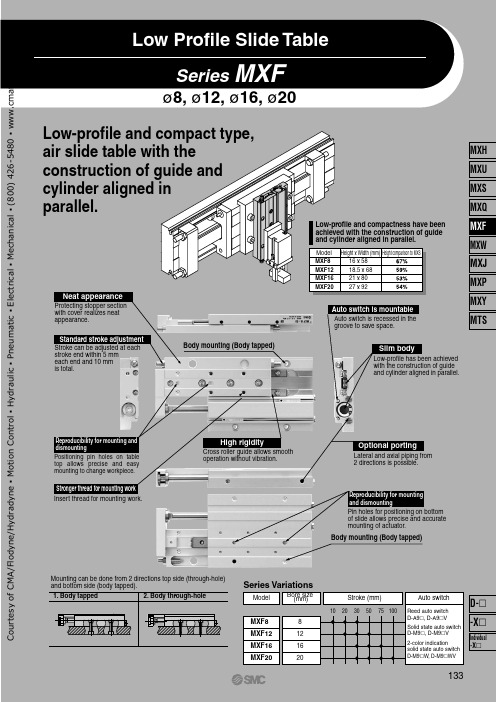
Series MXFø8, ø12, ø16, ø2020161281020305075100MXF20MXF16MXF12MXF8MXF8MXF12MXF16MXF2016 x 5818.5 x 6821 x 8027 x 92Low Profile Slide TableLow-profile and compact type, air slide table with the construction of guide and cylinder aligned in parallel.Low-profile and compactness have been achieved with the construction of guide and cylinder aligned in parallel.Model Height x Width (mm)Height comparison to MXS Stronger thread for mounting workHigh rigidityOptional portingReproducibility for mounting and dismountingAuto switch is mountableSlim bodyStandard stroke adjustmentReproducibility for mounting and dismountingNeat appearanceStroke can be adjusted at each stroke end within 5 mm each end and 10 mm is total.Insert thread for mounting work.Cross roller guide allows smooth operation without vibration.Lateral and axial piping from 2 directions is possible.Pin holes for positioning on bottom of slide allows precise and accurate mounting of actuator.Body mounting (Body tapped)Auto switch is recessed in the groove to save space.Low-profile has been achieved with the construction of guide and cylinder aligned in parallel.Body mounting (Body tapped)Protecting stopper section with cover realizes neat appearance.Positioning pin holes on table top allows precise and easy mounting to change workpiece.2. Body through-hole1. Body tappedMounting can be done from 2 directions top side (through-hole) and bottom side (body tapped).Bore size (mm)Auto switchStroke (mm)Series VariationsModelReed auto switch D-A9 , D-A9 V Solid state auto switch D-M9 , D-M9 V 2-color indicationsolid state auto switch D-M9 W, D-M9 WV133MXH MXU MXS MXQ MXF MXW MXJ MXP MXY MTSIndividual -XD- -XC o u r t e s y o f C M A /F l o d y n e /H y d r a d y n e ▪ M o t i o n C o n t r o l ▪ H y d r a u l i c ▪ P n e u m a t i c ▪ E l e c t r i c a l ▪ M e c h a n i c a l ▪ (800) 426-5480 ▪ w w w .c m a f h .c o m3-13-23-33-4123L 2+A 5L 3L 1Series MXFModel SelectionModel Selection StepFormula/Data Selection ExampleOperating ConditionsKinetic EnergyLoad FactorLoad factor of load massLoad factor of the static momentLoad factor of dynamic momentSum of the load factorsFind the kinetic energy E (J) of the load.Find the allowable kinetic energy Ea (J).Confirm that the kinetic energy of the load does not exceed the allowable kinetic energy.Use is possible if the sum of the load factors does not exceed 1.Enumerate the operating conditions considering the mounting position and workpiece configuration.• Model to be used • Type of cushion• Workpiece mounting position • Mounting orientation • Average speed Va (mm/s)• Load mass W (kg): Fig. (1)• Overhang Ln (mm): Fig. (2)E = -· W (-)2Collision speed V = 1.4 ·Va Ea = K·EmaxWorkpiece mounting coefficient K: Fig. (3)Max. allowable kinetic energy Emax: Table (1)Kinetic energy (E) Allowable kinetic energy (Ea)—∗12V1000∗) Correction factor (Reference values)Cylinder: MXF20-50Cushion: Rubber bumper Workpiece table mounting Mounting: Horizontal wall mounting Average speed: Va = 300 [mm/s]Allowable load: W = 0.5 [kg]L 1 = 10 mm L 2 = 30 mm L 3 = 30 mmRollingYawingPitchingYawing134C o u r t e s y o f C M A /F l o d y n e /H y d r a d y n e ▪ M o t i o n C o n t r o l ▪ H y d r a u l i c ▪ P n e u m a t i c ▪ E l e c t r i c a l ▪ M e c h a n i c a l ▪ (800) 426-5480 ▪ w w w .c m a f h .c o mSymbolAn (n = 1 to 6)E Ea EmaxLn (n = 1 to 3)M (Mp, My, Mr)Ma (Map, May, Mar)Me (Mep, Mey)Mea (Meap, Meay)Mmax (Mpmax, Mymax, Mrmax)VUnit mm J J J mm N·m N·m N·m N·m N·m mm/sSymbol Va W Wa We WmaxUnit mm/s kg kg kg kg ——————————MXF8MXF12MXF16MXF20100.56——————200.781.65————300.982.223.416.6650——3.345.699.1475————7.9613.70100——————18.271.00.70.50.40.30.2501002003005007001.00.70.50.40.30.250100200300500700MXF8MXF12MXF16MXF20MXF8MXF12MXF16MXF200.61 2 4WWWWK = 1K = 0.6MepWWMpWMpL 1A 1L 1A 2L 3A 2WMrWMrL 3A 5L 3A 6L 2A 3L 2A 4WMyWMyMeyL 2A 4MXF8MXF12MXF16MXF20A 16101011A 210111217A 36101011A 421232834A 521232834A 610111217SymbolTable (4) Maximum Allowable Moment: Mmax (N·m)Fig. (1) Load mass: W (kg)Fig. (2) Overhang: Ln (mm), Correction Values for Moment Center Distance: An (mm)Table (1) Maximum Allowable KineticEnergy: Emax (J)Table (2) Maximum AllowableLoad mass: Wmax (kg)Fig. (3) Workpiece MountingCoefficient: KTable (3) Moment Center Position DistanceCompensation Amount: An (mm)Pitch momentY aw momentRoll momentD y n a m i c m o m e n tS t a t i c m o m e n tNote) Static moment: Moment generated by gravityDynamic moment:Moment generated by impact whencolliding with stopperNote) No need to consider this load factor inthe case of using perpendicularly in a vertical position.T able mountingEnd plate mountingModelAllowable kinetic energyRubber bumper0.0270.0550.110.16ModelMaximum allowable load massNote) 16 mm for MXF8-10 only.ModelMoment center position distance compensation amount (Refer to Fig. (2).)Note)Note)Average speed Va (mm/s)Note) Use the average speed when calculating static moment.Use the collision speed when calculating dynamic moment.Average speed Va (mm/s)Collision speed V (mm/s)DefinitionCorrection values of moment center position distance Kinetic energyAllowable kinetic energyMax. allowable kinetic energy OverhangStatic moment (pitch, yaw, roll)Allowable static moment (pitch, yaw, roll)Dynamic moment (pitch, yaw)Allowable dynamic moment (pitch, yaw)Maximum allowable moment (pitch, yaw, roll)Collision speedDefinitionAverage speed Load massAllowable load mass Mass equivalent to impact Max. allowable load mass Load factorA llowable load mass coefficient Allowable moment coefficient Damper coeficientWorkpiece mounting coefficient ModelStroke (mm)135Low Profile Slide Table SeriesMXFMXHMXU MXS MXQ MXF MXW MXJ MXPMXY MTSIndividual -XD- -XC o u r t e s y o f C M A /F l o d y n e /H y d r a d y n e ▪ M o t i o n C o n t r o l ▪ H y d r a u l i c ▪ P n e u m a t i c ▪ E l e c t r i c a l ▪ M e c h a n i c a l ▪ (800) 426-5480 ▪ w w w .c m a f h .c o m10, 20, 3020, 30, 5030, 50, 7530, 50, 75, 100ø8ø12ø16ø20Nil S nMXF 1250M9BWø8ø12ø16ø208121620MXF A 16X11Nil X11X125 mm 15 mm 25 mm27∗ Lead wire length symbols: 0.5 m ·················Nil (Example) M9NW 1 m ·················M (Example) M9NWM 3 m ·················L (Example) M9NWL 5 m ·················Z (Example) M9NWZA96V A93V A90VM9NV M9PV M9BV M9NWV M9PWV M9BWV A96A93A90M9N M9P M9B M9NW M9PW M9BW 3-wire (NPN equivalent)—24 V24 V 2-wireN o3-wire (NPN)3-wire (PNP)2-wire 3-wire (NPN)3-wire (PNP)2-wire DC ACPerpendicularIn-line0.5(Nil)5(Z)—100 V 100 V or less ———————1(M)—————Diagnostic indication (2-color indication)5 V 12 V5 V,12 V12 V 5 V,12 V 12 V3(L)How to OrderMade to OrderRefer to page 137 for details.2 pcs. 1 pc. “n” pcs.Number of auto switches∗ For the applicable auto switch model, refer to the table below.Auto switchNilWithout auto switch (Built-in magnet)Bore size/Stroke (mm)How to Order Stroke Adjusting Bolt (Accessory)Applicable bore sizeAdjustment rangeStandard Option∗ -X12 (adjustable range 25 mm) is not available in Series MXF8/MXF12.Applicable Auto Switch /Refer to pages 1719 to 1827 for the detailed specifications of auto switches.Special functionT ype Electrical entry Wiring (Output)Load voltage Auto switch model Lead wire length (m)Applicable load Pre-wiredconnectorI n d i c a t o r l i g h tIC circuit ICcircuit ICcircuit IC circuit Relay,PLC Relay,PLC————Y e sY e s GrommetGrommetR e e d s w i t c hS o l i d s t a t e s w i t c h∗ Solid state auto switches marked with “ ” are produced upon receipt of order.∗ Since there are other applicable auto switches than listed, refer to page 145 for details.∗ For details about auto switches with pre-wired connector, refer to pages 1784 and 1785.∗ Auto switches are shipped together (not assembled).136Low Profile Slide TableSeries MXFLow Profile Slide TableC o u r t e s y o f C M A /F l o d y n e /H y d r a d y n e ▪ M o t i o n C o n t r o l ▪ H y d r a u l i c ▪ P n e u m a t i c ▪ E l e c t r i c a l ▪ M e c h a n i c a l ▪ (800) 426-5480 ▪ w w w .c m a f h .c o mSymbolMXF 8MXF 120.060.040.02102030400.08MXF8-30MXF8-20MXF8-10102030MXF8-10MXF8-20MXF8-300.030.020.01102030400.04MXF8-20MXF8-30MXF8-100.030.020.010000.060.040.02204060MXF12-30MXF12-20MXF12-500.080.10204060MXF12-30MXF12-50MXF12-2020406080MXF12-30MXF12-20MXF12-500.080.060.040.020.060.040.02000Lr = 20 mmLr = 30 mmFAALrTable Deflection (Reference Values)Table displacement due to pitch moment loadTable displacement due to yaw moment loadTable displacement due to roll moment loadT able displacement when loads are applied to the section marked with the arrow at the full stroke.T able displacement when loads are applied to the section marked with the arrow at the full stroke.T able displacement of section A when loads are applied to the section F with the slide table retracted.Load (N)T a b l e d i s p l a c e m e n t a m o u n t (m m )Load (N)T a b l e d i s p l a c e m e n t a m o u n t (m m )Load (N)T a b l e d i s p l a c e m e n t a m o u n t (m m )Load (N)T a b l e d i s p l a c e m e n t a m o u n t (m m )Load (N)T a b l e d i s p l a c e m e n t a m o u n t (m m )Load (N)T a b l e d i s p l a c e m e n t a m o u n t (m m )138Series MXFC o u r t e s y o f C M A /F l o d y n e /H y d r a d y n e ▪ M o t i o n C o n t r o l ▪ H y d r a u l i c ▪ P n e u m a t i c ▪ E l e c t r i c a l ▪ M e c h a n i c a l ▪ (800) 426-5480 ▪ w w w .c m a f h .c o mMXF 16MXF 200.080.160.040.120.2020406080100MXF16-50MXF16-30MXF16-751206004080100MXF16-75MXF16-50MXF16-3020406080100MXF16-75MXF16-50MXF16-300.010.030.050.060.020.040.070.010.030.050.060.020.040.07000.160.240.08MXF20-100MXF20- 75MXF20- 50MXF20- 300.120.200.28MXF20-100MXF20-75MXF20-50MXF20-30MXF20-100MXF20- 30MXF20- 50MXF20- 750.100.080.040.020.060.040.020.0650100150408012024020016020050100150200000Lr = 40 mmLr = 50 mmFAALr200.04Load (N)T a b l e d i s p l a c e m e n t a m o u n t (m m )Load (N)T a b l e d i s p l a c e m e n t a m o u n t (m m )Load (N)T a b l e d i s p l a c e m e n t a m o u n t (m m )Load (N)T a b l e d i s p l a c e m e n t a m o u n t (m m )Load (N)T a b l e d i s p l a c e m e n t a m o u n t (m m )Load (N)T a b l e d i s p l a c e m e n t a m o u n t (m m )Table displacement due to pitch moment loadTable displacement due to yaw moment loadTable displacement due to roll moment loadTable displacement when loads are applied to the section marked with the arrow at the full stroke.Table displacement when loads are applied to the section marked with the arrow at the full stroke.Table displacement of section A when loads are applied to the section F with the slide table retracted.The graphs below show the table displacement when the static moment load is applied to the table. The graphs do not show the loadable mass. Refer to the Model Selection for the loadable mass.139Low Profile Slide Table SeriesMXFMXHMXU MXSMXQ MXF MXW MXJ MXPMXYMTSIndividual -XD- -XC o u r t e s y o f C M A /F l o d y n e /H y d r a d y n e ▪ M o t i o n C o n t r o l ▪ H y d r a u l i c ▪ P n e u m a t i c ▪ E l e c t r i c a l ▪ M e c h a n i c a l ▪ (800) 426-5480 ▪ w w w .c m a f h .c o mMXF8-PS MXF12-PS MXF16-PS MXF20-PS8121620MXF-A827MXF-A827-X11MXF-A1227MXF-A1227-X11MXF-A1627MXF-A1627-X11MXF-A1627-X12MXF-A2027MXF-A2027-X11MXF-A2027-X125155155152551525172723.533.526.536.546.53040506781222.534M4 x 0.7M5 x 0.8M6 x 1M8 x 1MXF8MXF12MXF16MXF20ABCMAMCB w!9!8i!5u !7q!0!6t!3!4!2rey o!1No.123456Description Material Note Component PartsDescription Material NoteNo.16171819Component Parts789101112131415Body Table End plate Rail Guide RodPiston assembly Seal support Head capFloating bushing OrificeRoller stopper Cylindrical roller Roller spacer Rod bumperAluminum alloy Aluminum alloy Aluminum alloy Carbon tool steel Carbon tool steel Stainless steel—Brass Resin Stainless steelBrass Stainless steel High carbon chrome bearing steelResin PolyurethaneHard anodized Hard anodized Hard anodized Heat treated Heat treated With magnet Electroless nickel plated Electroless nickel plated Adjust bumper Piston seal Rod seal O-ring PolyurethaneNBR NBR NBRReplacement Parts: Seal KitBore size (mm)Kit no.Set of nos. above !7 to !9∗ Seal kit includes !7, !8, !9. Order the seal kit, based on each bore size.ContentsReplacement Part: Grease PackApplied part GuideCylinderGrease pack part no.GR-S-005 (5 g) GR-S-010 (10 g)GR-S-020 (20 g)GR-S-050 (50 g)GR-L-005 (5 g) GR-L-010 (10 g)GR-L-020 (20 g)GR-L-050 (50 g)Applicable sizeModel Stroke adjustable range (mm)140Series MXFConstructionDimensions: Stroke Adjusting BoltC o u r t e s y o f C M A /F l o d y n e /H y d r a d y n e ▪ M o t i o n C o n t r o l ▪ H y d r a u l i c ▪ P n e u m a t i c ▪ E l e c t r i c a l ▪ M e c h a n i c a l ▪ (800) 426-5480 ▪ w w w .c m a f h .c o m14618211358F (Equal pitch)A4N x M3 x 0.5 thread depth 6.5(Insert)3H 9 d e p t h 3+0.02503H 9 d e p t h 3+0.0250486A´GH192 x M3 x 0.5 thread depth 6159.54.584.74 x ø6.54.74 x ø3.24 x M4 x 0.70.315M(T able length)8164.5Max. 9J Z ZZ2.4821HG 4ModelMXF8-10MXF8-20MXF8-30F202626G13.514.514.5H222640J212641M495469Z49.554.569.5ZZ586378N446Operating port 2 x M3 x 0.510.5353120.5Note) If long bolts are used, they cantouch the guide block and cause malfunction, etc.Refer to the Specific ProductPrecautions.Stroke adjuster at extension end Stroke adjuster at retraction endWidth across hexagon socket hole 2Width across flats 6ø3H9 +0.0250 depth 3N2( – 1) x F ∗Note)Blanking plug (M-3P 2 points)Possible to use asoperating port 2 x M3 x 0.5N2∗ ( – 1): The number of pitches Section AA´ø3H9 depth 3+0.0250(mm)141Dimensions: MXF8Low Profile Slide Table SeriesMXFMXH MXU MXS MXQ MXFMXWMXJ MXP MXYMTSIndividual -XD- -XC o u r t e s y o f C M A /F l o d y n e /H y d r a d y n e ▪ M o t i o n C o n t r o l ▪ H y d r a u l i c ▪ P n e u m a t i c ▪ E l e c t r i c a l ▪ M e c h a n i c a l ▪ (800) 426-5480 ▪ w w w .c m a f h .c o mModelMXF12-20MXF12-30MXF12-50N446H223065I111213J364580M6575111Z6575111ZZ76861225869.85.52010254A20.5231668A´25H168.5204M(Table length)10J Z ZZ318.55.5H25230.3176.54 x M4 x 0.76.54 x ø6.54 x ø3.2I10.54524.535Stroke adjuster at extension end Stroke adjuster at retraction end Width across hexagon socket hole 2.5Width across flats 72 x M3 x 0.5 thread depth 6ø3H9 +0.0250 depth 3N 2( – 1) x 25∗N x M3 x 0.5 thread depth 5.5(Insert)Note)Blanking plug (M-5P 2 points)Possible to use asoperating port 2 x M5 x 0.83H 9 d e p t h 3+0.0250Max. 10.5Operating port 2 x M5 x 0.83H 9 d e p t h 3+0.025ø3H9depth 3+0.0250(mm)Note) If long bolts are used, they cantouch the guide block and cause malfunction, etc.Refer to the Specific ProductPrecautions.N2∗ ( – 1): The number of pitches Section AA´142Series MXFDimensions: MXF12C o u r t e s y o f C M A /F l o d y n e /H y d r a d y n e ▪ M o t i o n C o n t r o l ▪ H y d r a u l i c ▪ P n e u m a t i c ▪ E l e c t r i c a l ▪ M e c h a n i c a l ▪ (800) 426-5480 ▪ w w w .c m a f h .c o mModelMXF16-30MXF16-50MXF16-75N466G292939H255545NN446I121213J5080125M83113159Z83113159ZZ94124170243558027.520HG2312.55.511.5182597M(Table length)100.319.5J Z ZZ3HG 27.556876.76.7N N x ø8NN x M5 x 0.8N N x ø4.2IAA´12.55241.528.521Width across hexagon socket hole 3Width across flats 8Stroke adjuster at retraction end Stroke adjuster at extension end2 x M4 x 0.7 thread depth 10ø4H9 +0.0300 depth 4N 2( – 1) x 35∗NN 2( – 1) x H 4H 9d e p t h 4 +0.030 0N x M4 x 0.7 thread depth 6.5(Insert)Note)Blanking plug (M-5P 2 points)Possible to use asoperating port 2 x M5 x 0.8Operating port 2 x M5 x 0.8Max. 9ø4H9+0.030depth 44H 9d e p t h 4 +0.030 0Section AA´N2∗ ( – 1): The number of pitches(mm)Note) If long bolts are used, they cantouch the guide block and cause malfunction, etc.Refer to the Specific ProductPrecautions.143Dimensions: MXF16Low Profile Slide Table SeriesMXFMXHMXU MXS MXQMXF MXWMXJ MXP MXY MTSIndividual-XD- -XC o u r t e s y o f C M A /F l o d y n e /H y d r a d y n e ▪ M o t i o n C o n t r o l ▪ H y d r a u l i c ▪ P n e u m a t i c ▪ E l e c t r i c a l ▪ M e c h a n i c a l ▪ (800) 426-5480 ▪ w w w .c m a f h .c o mModelMXF20-30MXF20-50MXF20-75MXF20-100N4466G29364059H30454560NN4466J5777125175M91113162211Z91113162211ZZ104126175224286069233.525A789HG0.525M(T able length)1227712Z ZZ3HG 33.562230122611.5135.58.58.5N N x ø8NN x M5 x 0.8N N x ø4.2J 641551.537Width across hexagon socket hole 4Width across flats 12Stroke adjuster at retraction end Stroke adjuster at extension end2 x M5 x 0.8 thread depth 12N2( – 1) x 60∗ø5H9 +0.030depth 5NN2( – 1) x H 5H 9d e p t h 5 +0.030 0Note)Blanking plug (M-5P 2 points)Possible to use asoperating port 2 x M5 x 0.8Operating port 2 x M5 x 0.8Max. 9.5Section AA´N2∗ ( – 1): The number of pitches A´Note) If long bolts are used, they cantouch the guide block and cause malfunction, etc.Refer to the Specific ProductPrecautions.ø5H9+0.030depth 55H 9d e p t h 5 +0.030 0(mm)144Series MXFDimensions: MXF20N x M5 x 0.8 thread depth 9.5(Insert)C o u r t e s y o f C M A /F l o d y n e /H y d r a d y n e ▪ M o t i o n C o n t r o l ▪ H y d r a u l i c ▪ P n e u m a t i c ▪ E l e c t r i c a l ▪ M e c h a n i c a l ▪ (800) 426-5480 ▪ w w w .c m a f h .c o mReed Auto Switch: D-A90, D-A93, D-A96, D-A90V, D-A93V, D-A96VSolid State Auto Switch: D-M9B, D-M9N, D-M9P, D-M9BW, D-M9NW, D-M9PWSolid State Auto Switch: D-M9BV, D-M9NV, D-M9PV, D-M9BWV, D-M9NWV, D-M9PWVEABMXF8MXF12MXF16MXF209.51217.219.41010———20513.1——301013.115.820.750—29.125.822.775——46.846.2100———70.710———20——3050—75——100———BE MXF8MXF12MXF16MXF2013.51621.223.41014———20917.1——301417.119.824.750—33.129.826.775——50.850.2100———74.710———20——3050—75——100———BE MXF8MXF12MXF16MXF2013.51621.223.41014———20917.1——301417.119.824.750—33.129.826.775——50.850.2100———74.7106———2019.1——3069.111.816.750—25.121.818.775——42.342.2100———66.7BE 48(5.5)3(0.5)11.1(8.6)8(5.5)11.1(8.6)13.8(11.3)18.7(16.2)27.1(24.6)23.8(21.3)20.7(18.2)44.8(42.3)44.2(41.7)68.7(66.2)–17.147.19.814.723.119.816.740.840.264.7AAA(mm)(mm)(mm)D-A9 (V)D-M9 , M9 V D-M9 W, M9 WV84.5312531664.52075Tightening Torque of Auto Switch Mounting Screw Tightening torque 0.10 to 0.200.05 to 0.15D-A9 (V)D-M9 (V)D-M9 W(V)(N ·m)Other than the models listed in “How to Order”, the following auto switches are applicable.∗ Normally closed (NC = b contact) solid state auto switches (D-F9G/F9H types) and solid state auto switch D-F8 are also available.For details, refer to pages 1745 and 1746.Auto Switch Mounting Tool• When adjusting the auto switch mounting screw (included with auto switch), use a watchmaker´s screwdriver with a handle about 5 to 6 mm in diameter.Tightening TorqueStroke StrokeModel Stroke StrokeModel Stroke StrokeModel ∗ ( ): Denotes the values of D-A93.Note) Adjust the auto switch after confirming the operating conditions in the actual setting.Operating RangeApplicable bore size (mm)Auto switch modelAuto switch modelAuto Switch Mounting CautionAuto switch mounting screw (included with auto switch)Watchmaker´s screwdriverAuto switch∗ Since the operating range is provided as a guideline including hysteresis, it cannot be guaranteed (assuming approximately ±30 dispersion). It may vary substantially depending on an ambient environment.145Low Profile Slide Table SeriesMXFAuto Switch Proper Mounting Position (Detection at Stroke End)MXH MXU MXS MXQMXF MXW MXJ MXP MXYMTSIndividual -XD--XC o u r t e s y o f C M A /F l o d y n e /H y d r a d y n e ▪ M o t i o n C o n t r o l ▪ H y d r a u l i c ▪ P n e u m a t i c ▪ E l e c t r i c a l ▪ M e c h a n i c a l ▪ (800) 426-5480 ▪ w w w .c m a f h .c o mSeries MXFSpecific Product PrecautionsBe sure to read before handling. Refer to front matters 42 and 43 for Safety Instructions and pages 3 to 11 for Actuator and Auto Switch Precautions.MXF8MXF12MXF16MXF20M4 x 0.7M4 x 0.7M5 x 0.8M5 x 0.82.12.14.44.44.76.56.78.5MXF8MXF12MXF16MXF20M3 x 0.5M3 x 0.5M4 x 0.7M4 x 0.71.21.22.82.84.76.56.78.5MXF8MXF12MXF16MXF20M3 x 0.5M3 x 0.5M4 x 0.7M5 x 0.80.90.92.14.4661012MXF8MXF12MXF16MXF20M3 x 0.5M3 x 0.5M4 x 0.7M5 x 0.80.90.92.14.46.55.56.59.5LLLLMountingCautionCautionCautionPositioningSelection1.Do not scratch or dent the mounting side of the body, table or end plate. It causes play in the guide section and increases sliding resistance.2.Do not scratch or dent on the forward side of the rail or guide. It will result in looseness of the guide section and increased sliding resistance.3.Keep away from objects which are influenced by magnets.As the piston part has magnets built-in, do not allow close contact with magnetic disks, magnetic cards or magnetic tapes. Data may be erased.4.When mounting the body, use screws with appropriate length and do not exceed the maximum tightening torque.Tightening with a torque above the limit could malfunction. Whereas tightening insufficiently could result in misalignment or come to a drop.5.Be careful when adjusting stroke not to allow cylinder end plate to bottom out against cylinder body.1. The positioning hole on the table and on the bottom of the body does not have the same center. Positioning hole is meant to be for reproducibility for mounting and dismounting.1.If intermediate stop by external stopper is done, avoid ejection.If ejection occurs, it may cause damage.In the case the slide table is stopped at an intermediate position by an external stopper then forwarded to the front, return the slide table to the back for just a moment to retract the stopper, then supply pressure to the opposite port to operate slide table.2.Do not use it in such a way thatexcessive external force or impact force could work on it.This could result in damage.Mounting of BodyMounting of WorkpieceThe slide table can be mounted from 2 directions. Select the best direction according to your application.Work can be mounted on two sides of the body.1. Body Tapped2. Body Through-holeModel Bolt Maximumtightening torque (N·m)Maximum screw-indepth L (mm)Model Bolt Maximumtightening torque (N·m)Maximum screw-indepth L (mm)Model Bolt Maximumtightening torque (N·m)Maximum screw-indepth L (mm)Model Bolt Maximumtightening torque (N·m)Maximum screw-indepth L (mm)0.02 mm or less of flatness is recommended for the body mounting surface.An uneven mounting surface of a workpiece or a base may cause vibration or increase sliding resistance.Caution1. Front Mounting2. Top MountingFixing bolt for guideCautionTo prevent the workpiece holding bolts from touching the guide holding bolts, use bolts that are 0.5 mm or more shorter than the maximum screw-in depth.If the bolts are too long, they hit the end plate and may cause malfunctions.146C o u r t e s y o f C M A /F l o d y n e /H y d r a d y n e ▪ M o t i o n C o n t r o l ▪ H y d r a u l i c ▪ P n e u m a t i c ▪ E l e c t r i c a l ▪ M e c h a n i c a l ▪ (800) 426-5480 ▪ w w w .c m a f h .c o m。
M9 Pilot's Handbook - English ( Rev C )说明书

Pilot’s HandbookManuel de pilotage Pilotenhandbuch Pilotenhandboek Manual del Piloto取扱説明書See /manuals for Advance Guide40-00-2008Advanced Users Guide available @ /manualsRev C®CAUTION: This equipment has been tested and found to comply with the limits for a Class B digital device pursuant to Part 15 of FCC Rules. Operation is subject to the following two conditions: (1) This device may not cause harmful interference, and (2) this device must accept any interference received, including interference that may cause undesired operation.Important Safety InstructionsWARNING : TO REDUCE THE RISK OF FIRE OR ELECTRIC SHOCK, DO NOT EXPOSE THE APPLIANCE TO RAIN OR MOISTURE.WARNING : TO REDUCE THE RISK OF FIRE OR ELECTRIC SHOCK, DO NOT REMOVE SCREWS. NO USER-SERVICEABLE PARTS INSIDE.REFER SERVICING TO QUALIFIED SERVICE PERSONNEL.The lightning symbol within a triangle means “electrical caution!” It in-dicates the presence of information about operating voltage and potential risks of electrical shock.The exclamation point within a triangle means “caution!” Please read theinformation next to all caution signs.SERIAL NO:Please Note:Line 6 a nd M 9 a re t rademarks o f L ine 6, I nc. A ll o ther p roduct n ames, t rademarks, a nd a rtists’ n ames a re t he p roperty o f t heir r espective o wners, which a re i n n o w ay a ssociated o r a ffiliated w ith L ine 6. P roduct n ames, i mages, a nd a rtists’ n ames a re u sed s olely t o i dentify t he p roducts w hose t ones and s ounds w ere s tudied d uring L ine 6’s s ound m odel d evelopment f or t his p roduct. T he u se o f t hese p roducts, t rademarks, i mages, a nd a rtists’ n ames does not imply any cooperation or endorsement.The POD, Clifton House, Butler’s leap.Rugby, Warwickshire, United Kingdom, CV 21 3RQ 26580 Agoura Road,Calabasas, CA 91302-1921 USAYou s hould r ead t hese I mportant S afety I nstructions. K eep t hese i nstructions i n a s afe p lace• Read these instructions.• Keep these instructions.• Heed all warnings.• Follow all instructions.• Do not use this apparatus near water.• Clean only with dry cloth.• Do not block any ventilation openings. Install in accordance with the manufacturer’s instructions.• Do not install near any heat sources such as radiators, heat registers, stoves, or other apparatus (including amplifiers) that produce heat.• This apparatus shall be connected to a MAINS socket outlet with a protective earthing connection.• Do not defeat the safety purpose of the polarized or grounding-type plug. A polarized plug has two blades with one wider than the other. A grounding type plug has two blades and a third grounding prong. The wide blade or the third prong are provided for your safety. If the provided plug does not fit into your outlet, consult an electrician for replacement of the obsolete outlet.• Protect the power cord from being walked on or pinched particularly at plugs, convenience receptacles, and the point where they exit from the apparatus.• Only use attachments/accessories specified by the manufacturer.• Use only with the cart, stand, tripod, bracket, or table specified by the manufacturer, or sold with the apparatus. When a cart is used, use caution when moving the cart/apparatus combination to avoid injury from tip-over.• Unplug this apparatus during lightning storms or when unused for long periods of time.• Refer all servicing to qualified service personnel. Servicing is required when the apparatus has been damaged in any way, such as power-supply cord or plug is damaged, liquid has been spilled or objects have fallen into the apparatus, the apparatus has been exposed to rain or moisture, does not operate normally, or has been dropped.• The apparatus shall not be exposed to dripping or splashing and that no objects filled with liquids, such as vases, shall be placed on the apparatus.• WARNING: To reduce the risk of fire or electric shock do not expose this apparatus to rain or moisture.• The appliance coupler is used as the disconnect device, the disconnect device shall remain readily operable.• Connect only to AC power outlets rated: 100/120V 220/240V 50/60Hz (depending on the voltage range of the included power supply).• Prolonged listening at high volume levels may cause irreparable hearing loss and/or damage. Always be sure to practice “safe listening.”• Service is required when the apparatus has been damaged in any way, such as:• power-supply cord or plug is damaged.• liquid has been spilled or objects have fallen into the apparatus.• the unit has been exposed to rain or moisture.• the unit is dropped or the enclosure is damaged.• the unit does not operate normally or changes in performance in a significant way.eaR onneCtions1. Cable Retainer - Wrap your power supply cable around this once ortwice to prevent an accidental disconnect.2. Power - Connect your Line 6 Power Supply here to power the unit.3. MIDI In/Out - Please see /manuals for the skinny onMIDI features, which allow you to remote control scene changes, FX unit memory selection, looper operation, expression pedals, and tap tempo. Plus dump and receive scene data via MIDI System Exclusive messages.4. Expression Pedal 1 + 2 - Compatible with standard expression pedals,including the Line6 EX-1. Control FX parameters in real time by assigning them to either of these expression pedal inputs. The Line6 expression pedal is a passive 10K ohm mono linear taper pot, using a standard 1/4 inch mono instrument cable.5. Stereo Input - When connecting your guitar or other mono source usethe L(MONO) input.6. Stereo Output - For mono output, use the L(MONO) output.asiC peRa tion1. FX (1,2,3) Units - You can run up to 3 effects at once. Each FX Unit has2 memories (A & B), which can run any model of any type (Distortion–yellow, Delay–green, Modulation–blue, Filter–purple & Reverb–orange.2. Memory Footswitches - All FX Units have 2 memories (A & B). Onlyone memory can be active at a time: its footswitch will be brightly lit, and colored to show the effect type. Inactive switches are dimly lit. Step on a footswitch to activate that memory. Step on an active memory switch to bypass the FX Unit.3. Display - Your display will show all the settings for the most recentlyselected FX Unit memory (shown in upper left corner of the display).The display illuminates the color of current effect type (Distortion–yellow, Delay–green, Modulation–blue, Filter–purple & Reverb–orange).When a currently displayed FX Unit is turned off the display will show the first active FX Unit in your signal chain. If no FX Units are on the display will read “All FX Bypassed”. To edit an active FX Unit thatis not currently displayed simply double tap the Memory Footswitch you would like to edit, or press and hold TAP and quickly press the MODEL SELECT knob to scroll through active FX Units.4. Model Select - Press in the knob to select an effect type (Delay,Modulation, Distortion, Filter or Reverb) you want. Then turn the knob to scroll through available effect models.5. Parameter Knobs - Use these knobs to edit current effect settings shownin your display. These knobs usually control the setting locations as shown in the diagram to your left.6. TAP - Tap your tempo on the switch a few times to set the time/speed/tempo of all TAP enabled effects.s Cenes & s Cene s etupYou can run your M9 Stompbox Modeler in Scene Select Mode giving you 6 scenes, each of which is a complete pedalboard, storing all the settings of the A/B memories of the 3 FX Units. We’ve loaded each scene with an example pedalboard, to get you inspired.3A Tap. Your display will now look similar to the display shown above. The 6 Scenes are displayed as A & B for each of the 3 FX rows. The currently active Scene is shown in the solid circle (FX2 Unit A in the example above). To select a differ-ent Scene, press any of the other 5 FX Unit Footswitches. Momentary Scene Mode is the default setting, so selecting a new scene puts you right into a whole new pedal board where you can turn effects off and on. Choosing Momentary or Latch Scene ModesSimultaneously press 1B+ 2B to enter setup then press the model encoder until you see this screen: Use your parameter knob (bottom center) to select between Momentary (MOMEN SCENE) or Latch (LATCH SCENE). When you are done, simultaneously press 1B + 2B to exit setup.Momentary Scene ModeIn Momentary Scene Mode, once you select a new Scene your display will then return to the basic view displaying the current settings of the first active FX Unit in your chain. You can now activate or bypass any FX Unit if you would like. Any changes you make to the Scene will automatically be saved, just like a traditional pedalboard setup. To select a new Scene, simultaneously press 3A + TAP, then press any A or B footswitch.Latch Scene ModeIn Latch Scene Mode, the only difference is when you access your Scenes (3A + TAP), the 6 Scenes remain on the display after you load a new Scene - you won’t see FX Unit settings in the LCD.This mode is exceptionally handy when you want to switch from one set of multiple effects to another. You can tweak individual effects in Latch mode by simply pressing 3A + Tap to toggle out of scene mode. After you are done tweaking just press 3A + Tap again.Scene SaveTo save your current set of FX Units settings to a scene or to copy your currently loaded Scene, press and hold 3A + TAP until the followingscreen appears:Now press the footswitch of the desired location you’d like to save your scene to. Your display should now read “Save Completed” for 2 seconds then return to normal operation for the mode your Scenes are set to.Scene FoldersYour M9 is equipped with 4 scene folders giving you a total of 24 scenes.To access a new folder press 3A + Tap to access your current scenes folder then turn the Model Select knob and select the folder you wish to load (1-4) then press any scene to load it. Scenes will now default to the new folder.L oopeR & s etupThe Looper in the M9 gives you up to 28 seconds of mono recording time at normal speed, or 56 seconds at half speed. Your loop will always run in mono, even if you’re running stereo FX.To begin, press and hold the TAP/Hold for Looper footswitch.Your TAP LED will now stay on. When in Loop mode you canstill use TAP to set FX tempo and speed - you just won’t have theLED flashing in time for reference.Press REC/ODUB to start recording your loop. You can pressREC/ODUB again to immediately end your loop and beginrecording as many overdubs as you’d like, or...Press PLAY/STOP to continue the loop without recording. Youcan still jam over your loop. It just won’t be overdubbed into yourloop. Press again to stop the loop playback.PLAY ONCE can be pressed from stop or during playback, tocause play to end when the loop completes.Hit a bad note? You can press UNDO/REDO to discard your lastoverddub. This is also handy if you just want to remove your lastoverdub momentarily. Press UNDO/REDO again to recall thediscarded overdub.Step on HALF SPEED while in playback mode and your loopwill now play back in half speed. Start a new loop in half speedwhen you need additional loop time - up to 56 seconds.The REV footswitch sets your playback to reverse. Reverse can-not be engaged during record - doing so will immediately stoprecording and start playback of your loop in reverse.Press and hold TAP to exit Loop Mode.Using FX while loopingAny effects you have on when entering Looper mode will remain in your signal path. To change your FX Units or Switch Scenes during looping press and hold TAP to exit loop mode, make your selections and then press and hold TAP to return to Loop mode. Setting your looper to “PRE” will apply FX to your guitar signal only. In the Setup Menu setting the looper to “POST” will apply FX to your loop recording and your guitar signal.Looper SetupTo view and edit setup options for your Looper functionality you’ll need to access the setup screen. F irst, make sure you are in normal opera-tion - if you are currently in looper mode press and hold TAP to exit.Now simultaneously press 1B + 2B to enter setup then press the model encoder until you see this screen:Your bottom left knob switches your looper’ s audio path from Pre (your looper before FX Units) to Post (after FX Units). PLAY adjusts the level of your loop. OVERDUB adjusts the level of each overdub pass from 0dB to -20dB. LO CUT and HI CUT eq filters affect your recorded and looped audio only.D et aiLsConstant MemoryAs you adjust an effect (say, a Screamer distortion running in effect memory A of FX Unit 1), those adjustments are retained as you switch away to a different A/Bmemory and back again—no save function isrequired. It’s just as if you were adjusting different physical stompboxes, each of which would still have the last knob settings you made to it. The same is true as you switch scenes, swapping one virtual pedalboard for another: when you come back to a previously used scene, it loads with all the last adjustments you made to it.If you prefer that scenes not remember your last adjustments, simultane-ously press 1B + 2B to enter setup, then press the model encoder until you see this screen:Now set the Scenes parameter to MNL SAVE (Manual Save) instead of AUTOSAVE. You will then need to use the scene setup mode any time you want to manually force a “save” of current settings to a scene: Simultaneously press and hold TAP + 3A then select and hold on the same memory location you are currently on to “save”. Display will say “Save Completed”.Tap TempoTap tempo is available for all Delay effects, most MOD effects, and some Filter effects. For Delay and MOD effects turn the second top row knob or for Filters turn the first bottom row knob of the FX Unit all the way to max, and you’ll switch between tap tempo and regular control modes. Once you’re in Tap tempo control mode, turn the knob to select one of the available note values. Tap 2 or more times on the TAP switch, and all the effects set to tap tempo control will change their time/speed/ tempo to match the tempo you tapped. To end tap tempo operation for an effect, turn the knob to max again. NOTE: Parameters set to tap tempo control are NOT affected by expression pedal operation.TuningSimultaneously press 2B + 3B to enter Tuner Mode. All effects processing and looping will be bypassed. Use your lower left parameter knob to set your reference frequency. Use the lower right parameter knob to select either “BYPASS AUDIO” or “MUTE AUDIO” for silent operation.Mono / Stereo OperationSome models (like Stereo Delay) provide stereo operation. When run before a mono model (like a distortion), the signal will collapse to mono as it feeds the mono effect, and will then be passed on in mono to the next effect or outputs.Effect CopyAn effect can be copied to any other memory location within a scene.For example you can copy your effect in memory location FX Unit 1A to FX Unit 3B. To begin, select the memory location you would like to copy (the effect must be on and currently showing its parameters in your display). Press and hold the Model Select knob. Your display should read “Copy Effect: Select Destination”. Press the memory footswitch for the location you want to copy to. Your display now reads “Copy Completed”.Your copy is now stored in both the original and new location.a DDitionaL s etupAccess all the setup screens by simultaneously pressing 1B + 2B. Then press the MODEL SELECT knob to scroll through the different setuppages.True Bypass / DSP BypassChoose True Bypass when you want to remove the M9 Stomp Modeler from your signal path when all FX Units, Looper and Tuner are not inuse. When choosing DSP Bypass you’ll get the benefit of hearing delayand reverb trails smoothly decay when disengaging those effects. Signal Path Routing1>2>3 is standard operation with FX Unit 1 being the first FX in your chain and FX Unit 3 being the last. 3>2>1 reverses this order with FX Unit 3 being the first and FX Unit 1 being last. Hey, whatever floats your boat!DIM ON / OFFEnables the dimly lit footswitch LED’s when effect memories are by-passed (on) or disables them (off).Relative / Absolute PotsIn REL mode when you turn a knob the parameters will not jump to the position of the knob but change proportionally to the amount of your parameter knob movement up or down. When set to ABS it is not pos-sible to make incremental edits of an effect parameter. The parameter value always adjusts from the current pot position.TempoUse TEMPO to manually adjust your TAP tempo from 30 to 240 BPM instead of using the TAP footswitch.Expression PedalsThe remaining four parameters of this setup page are for Expression Pedal operation. Download the Advanced User Guide at www.line6.com/manuals for details.MIDI,Use “DUMP” to backup a scene, scene folder or all four folders to your computer. You can also restore the factory settings. The second param-eter is for assigning the MIDI channel your M9 Stompbox modeler sends and receives. Get the Advanced Guide at for details and download the Line 6 Monkey utility software to check for available upgrades and updates of the M9 Stompbox modeler firmware.GateThink of the Gate as a special additional pedal that applies to each scene. There is no footswitch control for this effect so only use it when you always want the gate engaged.ContrastThis sets the brightness of display.。
七彩虹 C.M9PV主板 说明书
描述 3PIN 跳线 4PIN 电源插口 20PIN 电源插口 3PIN 插头 1.8V 双 DIMM 40PIN 接口 IC芯片 电池插座 IC芯片 3PIN 跳线 IC芯片 4PIN 插头 34PIN FDD 接口 9PIN 扩展接头 BIOS 9PIN/4PIN插头 IC芯片 PCI 插槽 4PIN 音频线插口 7PIN 插头 4PIN 插头 IC芯片
SPDIF:
针脚 1 2 3 4 5
面板插针接口及 SPEAKER 接口:J2
定义 VCC NC OUT SPDIF IN GND
14
PDF 文件使用 "pdfFactory" 试用版本创建 ÿwÿ
硬件设定
电源指示灯PWR_LED(Power LED) 将机壳前面板的 POWER LED 指示灯接到此接脚上,当系统电源开启时, POWER灯也会亮起。 硬盘动作中指示灯HDD_LED(Hard Driver LED Header) 将机壳前面板的 HDD LED 指示灯接到此接脚上,便可经由此指示灯看 到硬盘运转的状况。 系统重置按钮 RESET(Reset Control) 将机壳前面板的 RESET 连接线接到此接脚上,若关闭此开关,则系统 将重置并执行开机自我测试(P O S T )。 电源开关按钮接脚 PWR_ON(Power Button) 将机壳前面板上的电源开关电缆连接至此接脚,便可以电源开关按钮打 开或者关闭计算机。 扬声器接脚 SPEAKER(Speaker) 透过此扬声器接脚,您可以外接一个扬声器到您的主板上,当计算机 开机正常无误时,此扬声器会发出一短[嘀]声,但若计算机开机时出现 不正常状况时,此扬声器会发出不规则长、短或高的[嘀嘀]声来提醒使 用者。
您可以通过短接 JCS 的 1-2 pins 来清除 CMOS 的数据,要清除 CMOS 必须完成以下步骤:
m9使用说明书

m9使用说明书在经过漫长的等待之后,终于盼到M9的到来,可惜不给力的联邦快递说当天送不到,我只能威胁加求情让他们给我送半程我自取,终于在下午6点半从联邦快递拿到心爱的M9。
废话少说,马上跟我进入M9体验之旅吧。
一、上手准备篇1、PC同步软件M9和M8的根本区别就在于采用不同的手机系统,所以同步软件也和M8是不通用的,在和电脑连接前我们必须准备适合M9使用的同步软件。
目前国内适合android机型的手机管理软件主要有两款:豌豆荚手机精灵和91手机助手。
两者都各有特色,这里就我自己的使用习惯采用豌豆荚手机精灵作为首选。
豌豆荚下载地址:/doc/089337928.html,/thread-254113-1-1.html(最新1.7版才支持M9,请注意,另外豌豆荚暂时不支持64位系统)2011-1-3 16:20 上传下载附件 (114.21 KB)下载后请自行安装,并进入下一步。
2、联系人备份文件使用M8的用户请使用系统自带备份备份联系人和短信,后面第三步就可以用M8的备份来恢复到M9上使用。
至于其他备份联系人方法后面补上。
二、连接PC篇1、手机端设置Android机型连接PC同步必须对手机端进行设置,设置步骤如下:点右边的触摸菜单键-设置-USB和开发模式-USB调试开启,详细请看截图(M9截图很简单,同时按下电源键+HOME键就可截图)。
2011-1-3 16:20 上传下载附件 (122.09 KB)点设置。
2011-1-3 16:20 上传下载附件 (35.95 KB)点USB和开发模式。
2011-1-3 16:20 上传下载附件 (46.08 KB)勾选USB调试,然后点确认。
2011-1-3 16:20 上传下载附件 (40.95 KB)设置完成。
2、连接PCUSB连接电脑,豌豆荚手机精灵会自动识别机型,并提示需要安装驱动,下面截图一步一步说明。
2011-1-3 16:20 上传下载附件 (42.65 KB)这里不要管,点取消。
Midmark M9 和 M11 UltraClave 自动蒸汽净化器产品说明书

Next M9&M11U L T R A C L A V E®The Midmark M9 and M11 UltraClave® Automatic Sterilizers - make sterilization reliable and efficient. T oday, more than ever, you need reliable and easy to use products from a trusted partner who understands your sterilization needs. The Midmark M9 and M11 UltraClave®Automatic Sterilizers are specifically designed and engineered to meet those needs. The intuitive display and simple prompts help you easily select the cycle you need whether it is for unwrapped items, pouches, packs or handpieces. Once the sterilization process is complete, the door conveniently opens automatically and quietly to dissipate the steam and provide fast and efficient drying of your instruments.Create peace of mind by making the dental market’s leading sterilizers...the Midmark M9 and M11 UltraClave®...your preferred office choice.Pouch RackM9 - 1 pouch rack M11 - 2 pouch racks Vertical Cassette Rack(M11 only)Holds four 8" x 11" and four3" x 8" cassettes.Horizontal Cassette Rack(M11 only)Holds four 8" x 11" and four3" x 8" cassettes.NOTE: Cycle times are approximate and may vary depending on instrument loads.Preset drying is 30 minutes but can be programmed from 0 to 60 minutes.W H A T D O Y O U W A N T I N A S T E R I L I Z E R?n Fast and easy use for efficient instrument processingn Reliability and effectiveness for infection control assurancen Patented automatic opening door for efficient instrument dryingn Maximum space utilization and a complimentary designfor your sterilization areaOur full line of sterilizers address all of your important criticalsterilization needs. In fact, we’re sure you’ll find a Midmarksterilizer that’s just right for your practice.Pulse-air Removal T echnologyThe Steam-Flush Pressure-Pulse Air Removal System is so efficient that it can pass the air removal tests required on more complex vacuum steam sterilizer systems, ensuring good steam penetration for those challenging loads. Plus, less complexity means better reliability and a cost effective solution for your sterilization needs.Convenience at a GlanceThe LCD display indicates cycle selected, cycle temperature and exposure time. When the cycle enters sterilization mode, the temperature, pressure and the remaining cycle time is displayed. Remaining cycle time is also displayed in the dry mode. Note: Temperature & pressure are not displayed during dry mode.No More Wet InstrumentsOnce sterilization is complete, the door opens automatically and quietly to dissipate steam and dry your instruments. You’ll have dry, sterile instruments every time.Safety FeaturesIf the door is not closed completely or the reservoir water level is low, the LCD display will provide the appropriate message. In either case, sterilization will not continue until you’ve attended to the unit.Ease of Draining & FillingFor ease of draining and filling, both the M9 and M11’s reservoir fill port and drain tube are in the front of the unit, not on top or in back.Optional Printer AccessoryThe M9 and M11 printer accessory provides a permanent record of cycle times, temperatures and pressures duringa cycle.Self Program Controls Programmable controls allowfor creation of different cycle parameters. Programmable buttons allow you to change the following: Exposure Time (3 to 90 minutes), T emperature (230 to 275º F), Dry Time (0 to 60 minutes) and Vent (slow or fast). The #1 and #2 buttons allow you to store the change if desired.Pre-Programed ControlsFour pre-programmedsterilization cycle controls:Unwrapped (132º C or 270º Ffor 3 minutes), Pouches (132ºC or 270º F for 5 minutes),Packs (121º C or 250º F for30 minutes), Handpieces(unwrapped and pouched)(132º C or 270º F for6 minutes).LCD DisplayIndicates cycle selected,temperature and exposuretime. During the cycle,the display shows messagesdescribing status of cycle.When the cycle enterssterilization mode, remainingtime is displayed as well astemperature and pressure.Cycle Start ButtonInitiates selected cycleManual Stop ButtonT erminates selected cycleor functionMidmark is an ISO 13485 and ISO 9001 Certified Company.For more information or a demonstration, contact your Midmark dealer or call: 1-800-MIDMARK Fax: 1-877-725-6495Outside the U.S.A. call: 1-937-526-3662 Fax: 1-937-526-8214 or visit our website at © 2007 Midmark Corporation60 Vista Drive P .O. Box 286 Versailles, Ohio 45380-0286 Products subject to improvement changes without notice Litho in U.S.A. 007-0640-00 Rev. C1 (9/09)SpecificationsM11D and M9D AutoClave ® SterilizersThe Midmark M9D and M11D AutoClave ® Automatic Sterilizers offer easy, effective sterilization, but without the convenience of a door that opens automatically. One button starts the cycle...but at the end of the automatic sterilization process, you need to manually open the door within 30 minutes of completion to activate the dry cycle. This extra step is the only physicaldifference between the M9D and M11D and their automatic counterparts.M3 UltraFast ® Automatic SterilizerThe Midmark M3 UltraFast ® Automatic Sterilizer allows you to rapidly process your instruments. The M3 provides reliable, fast sterilization and quicklydries your instruments.NEW。
飞利浦Xenium 9@9m说明书

飞利浦始终力争改善产品性能。
本用户指南所描述的信息与规格如有更改,恕不另行通知。
飞利浦力求确保该用户指南的信息均为准确,但不承担用户指南与产品之间存在的任何错误、遗漏或差异的责任。
本手机须连接到GSM/GPRS 网络。
如何操作...短信发送图标+-手机开机/关机长按)。
输入PIN 码用键盘输入PIN 码,并按,来确认。
拨打电话按,输入电话号码,然后按(拨号。
接听来电手机响起时,按(。
使用免提模式手机响铃时按下(,然后按L 选项,在选项列表中选择免提。
取消免提模式当手机处于通话中时,按L 选项,在选项列表中选择耳机。
结束通话按)。
拒接来电手机响起时按)。
进入主菜单待机模式下按,。
在浏览菜单时快速返回待机模式短按)。
硬按键功能键位于主屏幕下方的左右软键(L和R)让您可以选择屏幕中出现在软键正上方的相应选项,其中包括通话期间的选项。
这些键都是与手机当前的操作相关联的,即根据当前的手机状态而各不相同。
硬图标在触摸屏底部有4个固定硬图标,即(从左向右):主菜单、短信发送、电话簿和拨号。
这4个硬图标在待机模式下显示。
通话期间,短信发送和拨号图标仍可使用。
点击主菜单图标进入主菜单。
点击短信发送图标进入短消息编辑器。
点击电话簿图标进入电话簿列表。
点击拨号图标打开键盘,输入号码。
触摸屏警告!点击触摸屏时只能使用产品附带的触笔。
不要在触摸屏上使用其它工具。
进入菜单功能按,并使用触笔进入子菜单。
重复过程直至达到所需的功能。
使用拍照/摄像功能在待机模式下,短按相机键。
)挂机键• 在菜单或编辑模式下,短按以返回待机模式。
• 在来电或通话过程中按该键将中止当前呼叫或拒绝来电。
• 当手机关闭时,长按该键可以打开手机。
• 当手机开机时,长按该键可以关闭手机。
(接听键• 接听来电或拨出电话号码。
• 待机状态下,按该键可以查看所有通话列表。
照相机键• 在待机模式下,短按此键进入拍照模式。
手机上的触摸屏功能让您在列表和菜单之间快捷且直观的操作。
M9B 立体声无线耳机用户手册说明书

M9BStereo Wireless EarphonesUSER MANUAL Please read this manual in its entirety to ensure best fit and sound.PACKAGE CONTENTSM9BStereo Wireless Earphones1 pairof cable guidesUser manual Micro-USB charging cable4 pairs ofeartips1M9BStereo Wireless EarphonesPRODUCT OVERVIEWCHARGINGConnect the charging cable to any powered USB port and to the charging port located on the headset’s remote control.The status indicator light will stay red while charging and turn blue when fully charged.When the battery is low, the headset will say “battery low” and a red light on the remote will flash twice every two seconds.Apple® devices such as the iPhone®, iPad®, and iPod touch® will also display an on-screen headset battery indicator when the M9B is connected.Note: the lifetime of the battery will be significantly reduced if your headset is not charged for a long period of time. It is recommended to charge your headset at least once a month.3Wearing the M9B correctly will ensure the most comfortable and secure fit. STEP 1:Select and install the correct eartips.The M9B is an in-ear headphone and relies on a tight seal between eartip and ear canal to deliver great sound and bass. Four sizes of ear tips are included to help you achieve the best fit.We recommend trying all of them and selecting the ones with the best sound and comfort for your ears.STEP 2 (Optional):For a more secure sport-style fit, install the over-the-ear cable guides as shown.continued on next page45S TEP 3:Put the earphones in your ears. Adjust the earpieces for an airtight seal.When worn correctly, the earphones will reduce outside noise and deliver good bass impact. If you do not get much bass or hear tinny sound with excessive treble presence, re-adjust the fit of the earphones in your ears and/or try a different size of eartips.S TEP 4 (Optional):Adjust the cable cinch to reduce cable slack for a more secure andcomfortable fit.Make sure the M9B is turned off and within 3 feet (1 meter) of thedevice you wish to pair. Press and hold the Multifunction button forabout 4 seconds until the headset says “Pairing”. The status indicator light will flash red and blue in an alternating pattern while the M9B is in pairing mode.Note: The M9B will remain in pairing mode for 5 minutes or until paired.Open the Bluetooth menu on the device you wish to pair.Wait until you see “M9B” on the screen of your device.Select “M9B” on your device and follow any further prompts to pair.Use “0000” if a pin is required. Once connected, the headset will say “Connected” and the blue indicator light will flash three times every 9 seconds.6Computers, Laptops, and Other Devices Visit the Bluetooth Support Page at for pairing and setup information. BLUETOOTH PAIRINGYour headset must be paired to a Bluetooth device before it can be used. It is only necessary to pair your headset once with each device.1.2.3.4.iPhone, iPad, and iPod touchOn your device, open the Settings menuSelect Bluetooth. If Bluetooth is not on, turn it on.The iPhone/iPad/iPod® will automatically search for new devices.a)b)Android ™ Phones and TabletsOn your device, open the Settings menuSelect Bluetooth (on older Android devices Bluetooth isfound in the Wireless & Networks menu). If Bluetooth is not on, turn it on. Select “Search for Devices” or “Refresh” if your phone or tablet does not automatically search for new devices.a)b)Windows ® Phone 8 devicesOn your device, open the Settings menuSelect Bluetooth . If Bluetooth is not on, turn it on.Windows Phone 8 will automatically search for new devices.a)b)If pairing fails after several tries, please refer to your device’suser manual for additional information. Visit the Bluetooth Support Page at for instructional pairing videos and troubleshooting information.CONNECTING TO PAIRED DEVICESWhen turned on, the M9B will automatically connect with the last pairedand/or connected Bluetooth device that is powered on and within range.If the headset does not connect automatically, open the Bluetooth menuon your device and select “M9B” from the list of paired devices. CONNECTING TO PAIRED DEVICES (MULTIPOINT)Multipoint allows two Bluetooth devices to be connected to the M9B simultaneously. Both devices will need to be paired before multipointcan be used by following the pairing procedure described in the Bluetooth Pairing section for each device.To use two Bluetooth devices with the M9B, turn the unit on and wait untilit connects to the last paired device. Then, select “M9B” from the Bluetooth menu of second device you wish to connect. The headset cannot be connect-ed with more than two devices simultaneously.To switch between the two devices, pause audio playback on the active de-vice and start audio playback on the other connected device. It takes several seconds for the audio to switch.Incoming calls will always take precedence over media. When a call comes in, the M9B will automatically activate the device with the incoming call. Some devices, such as computers and standalone audio transmitters, do not allow audio switching except when a phone call occurs.If you no longer wish to connect to multiple devices, disable Bluetooth on the device you do not want connected to the M9B or remove the “M9B” pairing from the Bluetooth menu of that device.7FUNCTIONALITY & CONTROLS** Not all devices/applications support this functionality89SAFETY AND CARETo clean, remove the eartips and rinse them under running water.Clean the earphones using a cotton swab damp with a small amount of rubbing alcohol. Allow the earphones and eartips to dry completely before resuming e only the supplied Micro-USB charging cable or a compatible replacement from a reputable manufacturer.Battery performance will be severely decreased when stored in extreme temperatures: below -10°C/14°F or above 50°C/122°F, including direct sunlight.If the device comes in contact with liquids, quickly wipe away.If submersed in water, do not turn the device on until completely dried. Note: liquid submersion voids the warranty.Do not use around flammable gasses as fire may occur.••••••FACTORY RESETA factory reset will clear all paired devices from memory. To perform a factory reset, put the headset in pairing mode as described in the Bluetooth Pairing section, then press and hold the Volume up and Volume down buttons at the same time for 2 seconds. The headset will produce three tones and the blue indicator light will flash twice to indicate the memory has been cleared. The headset will need to be paired with a Bluetooth device before use.10WARNINGUsing headphones at high volumes for extended periods of time will result in permanent hearing damage. It is advised you keep volume levels moderate to low at all times for your safety. Turn the volume all the way down after connecting your earphones, then gradually increase the volume until you reach a comfortable listening level. Do not use while driving a car, cycling, operating machinery, or performing other activities that require hearing surrounding sounds.TROUBLESHOOTINGVisit the Bluetooth Support Page at for troubleshooting procedures.SPECIFICATIONSVisit the M9B product page at for product specifications.WARRANTY:The M9B is covered by a 1-year manufacturer warranty. For more information, visit MEE audio and its logo are registered trademarks of S2E, Inc. All rights reserved.iPhone , iPad , iPod , iPod touch , and Siri are registered trademarks of Apple Inc.Android™ is a registered trademark of Google Inc. Windows Phone is a registered trademark of Microsoft Corporation in the United States and other countries.The Bluetooth word mark and logos are registered trademarks owned by Bluetooth SIG, Inc. and any use of such marks by MEE audio is under license. Other trademarks and trade names are those of their respective owners.Have a question?Email ****************** ******************。
A9P型小型推开开关产品说明书

1Subminiature Pushbutton Switch A9PA9PSubminiature Pushbutton SwitchDouble-sided clip contact mechanism combined with see-saw action.•Gold-plated clip contact and cleaning mechanisms ensure high reliability.•Specially designed to prevent grease entry into the contact portion.•Sealed against flux entry.•Washable, equivalent to IP64 (IEC-60529).■List of Models●Without CapNote:1.(ON) shows Momentary. ON shows Alternate internally, even plunger is released Momentary.2.Plunger colorGray: Alternate Ivory: Momentary3.Order caps separately from switches as Accessories for other than red color, see Accessories.■Ratings/CharacteristicsRoHS CompliantSecurity Control BoardsElectric Power Instrumentation Program ControllersTypical ApplicationsRatings50 mA at 60 VAC/DC, 1 μA (minimum current) at 20 mVAC/DC Ambient operating temperature -20 to 80 °C 60% RH max. (with no icing or condensation)Ambient operating humidity 45 to 85%RH (5 to 35 °C )Insulation resistance 1,000 M Ω min. (Initial value)Contact resistance 50 m Ω max. (Initial value)Dielectric strength 500 VAC for 1 min between terminals, between terminals and ground Vibration resistance Malfunction 10 to 55 Hz, 1.5-mm double amplitude Shock resistance Malfunction 500 m/s 2 min.Durability Mechanical 50,000 operations min.Electrical50,000 operations min.Operating forceAlternate: 1.96 to 6.86 N {200 to 700 gf} / Momentary: 1.47 to 3.43 N {150 to 350 gf}WeightDIP Terminal0.7 g Right Angle Terminal 0.9 g Vertical Mount Terminal 0.9 gSubminiature Pushbutton Switch A9P2■Dimensions (Unit: mm)●DIP Terminal ●Right Angle Terminal ●Vertical Mount Terminal Note:Unless otherwise specified, a tolerance of ±0.4 mm applies to all dimensions.■PCB Dimensions (Top View)Without capNote:No. (1) and (3) terminals in the SPDT models are dummys to support the Switch case.Without capWithout capDIP TerminalVertical Mount TerminalRight Angle Terminal■Switching Functions / Internal ConnectionsNote:(ON) shows Momentary■Accessories●CapsAvailable wide range of col ors.■Safety PrecautionsBe sure to read the Safety precautions common to all PCB-mount Manual Switches for correct use.。
- 1、下载文档前请自行甄别文档内容的完整性,平台不提供额外的编辑、内容补充、找答案等附加服务。
- 2、"仅部分预览"的文档,不可在线预览部分如存在完整性等问题,可反馈申请退款(可完整预览的文档不适用该条件!)。
- 3、如文档侵犯您的权益,请联系客服反馈,我们会尽快为您处理(人工客服工作时间:9:00-18:30)。
LEICA M9 / M9-P / InstructionsIllustrations inside front and rear covers1.21.11.151.131.12a 1.12b1.12 1.12c1.13a1.201.20a 1.20b 1.141.21.3 1.4 1.5 1.71.6 1.81.91.19a1.19 1.111.181.171.161.20c 1.27 1.281.291.301.311.321.261.251.241.231.221.211.10本手冊圖例所顯示的是LEICA M9,另一款LEICA M9-P和這款相機僅有一些外觀上的差別,兩款相 機在功能用法與功能範圍方面皆相同。
The illustrations in these instructions show the LEICA M9. The model version LEICA M9-P differs only due to minor external details. In terms of functionality and scope of operation, both versions are identical.Leica M9 / M9-P 說明書English instructions on pages 90–177前言親愛的顧客,感謝您購買徠卡M9相機,並恭喜您慧眼獨具選擇了這台獨一無二的數位測距式相機。
衷心期望這台嶄新的徠卡M9相機,能帶給您許多攝影樂趣和滿意的成果。
我們建議您先閱讀本說明書,以便正確使用此台相機的所有功能。
本說明書以完全無氯漂白的紙張印製。
這種紙張的製程降低了排放到水道的毒素,進而保護了我們的環境。
2 / 前言3目錄前言 (2)警告提示 (6)法律提示 (6)電機與電子裝置的廢棄處置 (6)出貨內容 (7)各部名稱 (8)顯示訊息觀景窗內 (10)顯示螢幕上 (11)選單項目主選單 (14)攝影參數選單 (15)簡易說明 (16)詳細說明準備工作裝上揹帶 (18)電池充電 (18)將充電電池裝進相機/從相機取出 (20)充電狀態顯示 (20)插入及取出記憶卡 (21)徠卡M 型鏡頭 (22)裝上鏡頭 (23)拆下鏡頭 ..................................................... 23最重要的設定/操作元件打開及關閉相機/主開關 (24)選擇攝影及播放模式 (25)不限時播放 (25)自動播放最後一張相片 (25)快門按鈕 (26)連續拍攝 (27)快門時間設定轉盤 (28)顯示螢幕 (29)設定亮度 (29)在攝影作業模式裡顯示基本設定/日期 (29)在播放模式裡顯示拍攝日期 (29)階調分布圖 (30)選單操控功能 (31)主選單 (31)攝影參數選單 (31)設定選單功能 (32)預設功能相機基本設定選單語言 (34)日期及時間 (34)自動關機 (35)按鍵音及訊號音調 (35)攝影基本設定啟動/關閉鏡頭型號辨識功能 (36)解析度 (37)壓縮率/檔案格式 (37)白平衡 (38)自動或固定設定 (38)直接設定色溫值 (39)透過測量進行手動設定 (39)ISO 感光度 (40)影像特性 (對比、銳利度、色彩飽和度) (41)色彩管理 (42)正確握持相機 (42)取景框線-測距觀景窗......................... 43/45視野撥桿 (44)測距 (46)混合影像法 (雙重影像) (46)分割影像法 (46)4 /目錄測光 (47)打開/關閉測光表 (47)曝光模式 (48)光圈先決 (48)測光值儲存 (48)曝光修正 (49)自動包圍曝光 (51)手動設定曝光 (52)B快門設定/T 功能 (52)使用快照風格時曝光的設定 (53)測光表的測光範圍 (54)超出及低於曝光範圍 (54)關於閃光燈測光及控制的一般事項可用的閃光燈 (55)裝上閃光燈 (55)閃光燈作業 (56)閃光燈作業 (56)由相機所控制 (57)自動閃光燈模式的設定以相容系統閃光燈攝影時,觀景窗內的閃光燈控制顯示訊息 (57)自動閃光燈作業 (58)將閃光燈設定成 (58)電腦控制模式(A)或手動模式(M) (58)選擇同步時間/同步時間範圍 (59)選擇同步時間點 (60)其他功能使用者/使用者特定風格 (61)回復所有個別設定 (61)播放模式 (62)觀賞其他相片/記憶體內「翻頁」 (63)放大/選擇局部畫面/同時觀看多張縮小的相片 (63)刪除相片 (65)保護相片/取消防止刪除功能 (66)其他功能資料夾管理 (68)將記憶卡格式化 (69)以自拍器攝影 (69)將資料傳送到電腦上 (70)USB 連線 (70)使用 Windows®XP/Vista®/7® (70)使用 Mac®OS X (10.6) (71)使用讀卡機 (71)記憶卡上的資料結構 (72)處理DNG原始資料 (72)安裝韌體更新 (73)其他雜項徠卡M9的系統配件交換式鏡頭 (74)濾鏡 (74)泛用式M型廣角觀景窗 (74)適用於 21/24/28mm 鏡頭的觀景窗 (74)M型反射鏡式觀景窗 (74)觀景窗放大鏡M型1.25倍及1.4倍 (74)閃光燈 (75)M9 手把 (75)視力矯正目鏡 (75)相機袋 (75)替換零件 (75)安全及保養指示一般注意措施 (76)顯示螢幕 (77)凝濕氣 (77)保養指示相機 (77)鏡頭 (78)電池 (78)充電器 (79)記憶卡 (79)清潔感光元件 (80)存放 (82)故障及其排除方式 (83)關鍵字索引表 (84)技術資料及器材說明 (86)徠卡學院 (89)徠卡網站 (89)徠卡資訊服務 (89)徠卡客戶服務 (89)目錄 / 5警告提示• 僅能使用建議的配件,以避免干擾、短路 或電擊。
• 請勿讓器材暴露在濕氣或雨水中。
• 請勿嘗試拆除機身零件(外蓋);專業修理 工作僅能由獲得授權的維修單位執行。
法律提示:• 請遵守著作權法。
未經授權自行轉載或公開播放轉錄媒體,例如經由錄影帶、CD、他人發行或寄送的內容,皆有可能違反著作權法。
• 此點對於所有附贈的軟體亦然。
• SD符號為一種商標。
• 其他在本說明書裡提到的商標、公司及產品名稱皆為相關公司的商標及註冊商標。
電機及電子裝置的廢棄處置(適用於歐盟以及其他有獨立回收系統的歐洲國家)本裝置包含電機及/或電子組件,因此不得棄置於一般的家庭垃圾內!必須送到由地方政府設置的資源回收點,所提供免費的服務。
若裝置本身包含可交換式電池或充電電池,則必須事先將這些零件取出,且按當地規定進行廢棄處置。
其他和本主題相關的資訊,可從當地政府、廢棄物處理公司或在購買產品的商店處得知。
6 / 警告提示出貨內容開始操作徠卡M9相機之前,請先檢查附贈的配件是否齊全。
A. 電池B. 充電器C. USB連接訊號線D. 揹帶出貨內容 / 7各部名稱前視圖1.1 鏡頭解鎖鈕1.2 揹帶吊耳1.3 測距儀的視窗1.4 亮度感測器11.5 取景框線的採光窗1.6 含鏡射面的觀景窗物鏡,可在非常亮的環境下,清楚辨識觀景窗顯示的訊息1.7 自拍器發光二極體1.8 視野撥桿1.9 底蓋的固定扣相機鏡頭接座的前視圖/鏡頭接座的後視圖1.10 鏡頭辨識用感測器1.11 6-位元鏡頭辨識記號1有觀景窗座的徠卡M型鏡頭會遮住亮度感測器,關於這種或其他鏡頭使用方式的資訊,請看第10頁「顯示訊息/觀景窗內」及第22頁「徠卡M型鏡頭」這兩個章節。
上視圖1.12固定環,含a.對焦用指標b.景深範圍刻度尺及c.鏡頭更換用紅色指示鈕1.13對焦環,含a.握把1.14光圈設定環1.15光圈設定用白色指標點1.16遮光罩1.17快門時間設定轉盤,含–A快門時間自動控制的停格位置 1.18含各功能停格位置的主開關–OFF(相機關機)–S(單張拍攝)–C(連續拍攝)––(自拍器)1.19快門鈕,含a.線控快門線用螺紋1.20閃燈靴座,含a.中央(觸發)接點及b.控制接點,還有c.固定銷孔視圖見前面及後面的對折頁8 / 各部件名稱背視圖1.21SET-鍵,用於呼叫攝影參數選單/用於呼叫選單操控功能內的子選單/使用接受子選單內選擇的設定或功能。
1.22INFO-鍵,用於在攝影模式下顯示設定或日期/在播放模式下顯示拍攝日期1.23ISO-鍵,用於開啟感光度設定1.24DELETE鍵,用於選擇刪除功能1.25USB接頭上的蓋子1.26PLAY鍵,開啟(持續)播放作業/回到全畫面顯示模式1.27觀景窗目鏡1.28MENU鍵,用於開啟/關閉主選單1.29中央設定調整轉盤,用來操控選單/設定所選擇的選單項目或功能/設定曝光修正值/翻閱記憶體中的相片,以及放大/縮小所觀賞的相片1.30十字鍵,用於選單中的操控動作/設定所選擇的選單/功能項目/使用於相片記憶體中翻頁1.31顯示攝影進行中/資料儲存中/的訊號燈1.32顯示幕蓋子打開時的視圖1.33USB接頭(5針,用於和電腦連接)下視圖裝上底蓋時)1.34三腳架螺孔A 1/4, DIN 4503 (1/4“)1.35底蓋1.36底蓋的轉鈕取下底蓋時)1.37充電電池室1.38充電電池閂鎖推桿1.39記憶卡槽充電器1.40綠色(CHARGE)訊號燈顯示充電過程進行中1.41黃色(80%)訊號燈顯示:充電已滿80%1.42充電電池用充電槽,含a.接點1.43車用充電線接頭1.442針式接頭用於1.45可交換式電源線各部件名稱 / 9顯示訊息 2. 觀景窗內2.1藉由 LED(發光二極體) 顯示(有自動亮度控制功能,配合外界亮度1)用於:2.1.1.四位數七格式數位顯示,含位於上方和下方的點狀數位燈號數位顯示:–顯示光圈先決A時自動設定的快門時間,以及大於1秒的較長快門時間過程–光圈先決A下,超出及未達測光和設定範圍時的警告訊息–曝光修正值的顯示(調整設定中短暫出現)–(暫存資料用)暫存記憶體已滿的提示–SD卡未插入的提示 (Sd)–SD卡已滿的提示 (Full)上方點狀燈號:–使用測光值儲存功能的提示(恆亮)下方點狀燈號:–使用曝光修正功能的提示(閃爍)1含觀景窗座的徠卡M型鏡頭無法進行自動控制功能,因為它會遮住為該功能提供對應資訊的亮度感測器1.4在這種情形下,顯示訊息會持續以恆定的亮度顯示。
2.1.2 兩個三角形及一個圓形的LED訊號燈:– 使用快照設定:圓形LED燈號用來顯示曝光正確,右邊的三角形LED代表有過度曝光可能的情形,左邊的三角形LED代表有晃動及/或曝光不足– 手動調整設定時:共同作為曝光平衡的衡量指標– 警示超出測量範圍2.1.3閃光燈符號:– 閃光燈就緒– 攝影前後閃光燈曝光的數據資料2.2 50mm及75mm鏡頭用的取景框線(範例)2.3焦距設定用的對焦區2.1.12.1.32.1.22.32.22.110 / 顯示訊息 / 觀景視窗内顯示訊息 / 顯示螢幕上 / 113. 顯示螢幕上3.1攝影時(按下INFO 鍵,1.22)3.1.1 電池容量3.1.2 以MByte 為單位的剩餘記憶體容量3.1.3 剩餘可拍張數 3.1.4 設定/控制的快門時間3.1.5 鏡頭型號3.2 一般的播放(全螢幕顯示相片)3.2.1 防止刪除符號 (有設定此功能時才會出現)3.2.2 快門時間(放大顯示時不會出現)3.2.3 感光度 (放大顯示時不會出現)3.2.4 相片編號/現存相片總張數(放大顯示時不會出現)3.2.5 放大等級及所顯示局部畫面的位置(概要,只有在放大播放時才會出現)3.2.6 選取的相片(只適用於4格及9格縮小播放時)3.1.23.1.13.1.33.1.43.1.53.2.13.2.2 3.2.3 3.2.43.2.512 / 顯示訊息 / 顯示螢幕上3. 顯示螢幕上 (續)3.3提供額外資訊的播放(按下INFO 鍵,1.22;畫面縮小)3.3.1 畫面(視情況會有「截圖」顯示1)3.3.2 階調分布圖a. 明度(亮度)b. 紅/綠/藍分開顯示單一顏色)3.3.3 防止刪除符號(有設定此功能時才會出現3.3.4 快門時間 3.3.5 感光度3.3.6 相片編號/現存相片總數3.3.7 相片資料 a. 測光作業模式 b. 焦距2 c. 曝光修正值 d. 解析度 e. 壓縮率/檔案格式 f. 白平衡 g. 使用者風格名稱 i. 檔案編號 j. 放大等級,及顯示畫面局部的位置 有設定此功能時才會出現) k. 日期/時間1 請參閱第 30頁的「階調分布圖」。