VC0703-Datasheet芯片规格书之数据手册
FPGA可编程逻辑器件芯片XC7VX690T-3FFG1930C中文规格书

Virtex-5 Family OverviewDS100 (v5.1) August 21, 2015Product Specification Virtex-5 FPGA FeaturesThis section briefly describes the features of the Virtex-5 family of FPGAs.Input/Output Blocks (SelectIO)IOBs are programmable and can be categorized as follows:•Programmable single-ended or differential (LVDS)operation•Input block with an optional single data rate (SDR) or double data rate (DDR) register•Output block with an optional SDR or DDR register •Bidirectional block •Per-bit deskew circuitry •Dedicated I/O and regional clocking resources •Built-in data serializer/deserializerThe IOB registers are either edge-triggered D-type flip-flopsor level-sensitive latches.IOBs support the following single-ended standards:•LVTTL •LVCMOS (3.3V, 2.5V , 1.8V , 1.5V , and 1.2V)•PCI (33 and 66MHz)•PCI-X •GTL and GTLP •HSTL 1.5V and 1.8V (Class I, II, III, and IV)•HSTL 1.2V (Class 1)•SSTL 1.8V and 2.5V (Class I and II)The Digitally Controlled Impedance (DCI) I/O feature can beconfigured to provide on-chip termination for eachsingle-ended I/O standard and some differential I/Ostandards.The IOB elements also support the following differentialsignaling I/O standards:•LVDS and Extended LVDS (2.5V only)•BLVDS (Bus LVDS)•ULVDS •Hypertransport™•Differential HSTL 1.5V and 1.8V (Class I and II)•Differential SSTL 1.8V and 2.5V (Class I and II)•RSDS (2.5V point-to-point)Two adjacent pads are used for each differential pair. Two orfour IOB blocks connect to one switch matrix to access therouting resources.Per-bit deskew circuitry allows for programmable signaldelay internal to the FPGA. Per-bit deskew flexibly providesfine-grained increments of delay to carefully produce arange of signal delays. This is especially useful forsynchronizing signal edges in source-synchronousinterfaces.General purpose I/O in select locations (eight per bank) aredesigned to be “regional clock capable” I/O by addingspecial hardware connections for I/O in the same locality.These regional clock inputs are distributed within a limitedregion to minimize clock skew between IOBs. Regional I/Oclocking supplements the global clocking resources.Data serializer/deserializer capability is added to every I/O to support source-synchronous interfaces. A serial-to-parallel converter with associated clock divider is included in the input path, and a parallel-to-serial converter in the output path.An in-depth guide to the Virtex-5 FPGA IOB is found in the Virtex-5 FPGA Tri-Mode Ethernet MAC User Guide . Configurable Logic Blocks (CLBs)A Virtex-5 FPGA CLB resource is made up of two slices. Each slice is equivalent and contains:•Four function generators •Four storage elements •Arithmetic logic gates •Large multiplexers •Fast carry look-ahead chain The function generators are configurable as 6-input LUTs or dual-output 5-input LUTs. SLICEMs in some CLBs can be configured to operate as 32-bit shift registers (or 16-bit x 2 shift registers) or as 64-bit distributed RAM. In addition, the four storage elements can be configured as either edge-triggered D-type flip-flops or level sensitive latches. Each CLB has internal fast interconnect and connects to a switch matrix to access general routing resources.The Virtex-5 FPGA CLBs are further discussed in the Virtex-5 FPGA User Guide .Block RAM The 36Kbit true dual-port RAM block resources are programmable from 32K x 1 to 512x 72, in various depth and width configurations. In addition, each 36-Kbit block can also be configured to operate as two, independent 18-Kbit dual-port RAM blocks. Each port is totally synchronous and independent, offering three “read-during-write” modes. Block RAM is cascadable to implement large embedded storage blocks. Additionally, back-end pipeline registers, clock control circuitry, built-in FIFO support, ECC, and byte write enable features are also provided as options.The block RAM feature in Virtex-5 devices is further discussed in the Virtex-5 FPGA User Guide .Virtex-5 Family OverviewDS100 (v5.1) August 21, 2015Product SpecificationVirtex-5 LXT, SXT, TXT, and FXT Platform FeaturesThis section briefly describes blocks available only in LXT , SXT, TXT, and FXT devices.Tri-Mode (10/100/1000Mb/s) Ethernet MACsVirtex-5 LXT, SXT, TXT, and FXT devices contain up to eightembedded Ethernet MACs, two per Ethernet MAC block.The blocks have the following characteristics:•Designed to the IEEE 802.3-2002 specification •UNH-compliance tested •RGMII/GMII Interface with SelectIO or SGMII interface when used with RocketIO transceivers•Half or full duplex •Supports Jumbo frames •1000 Base-X PCS/PMA: When used with RocketIO GTP transceiver, can provide complete 1000 Base-Ximplementation on-chip•DCR-bus connection to microprocessors Integrated Endpoint Blocks for PCI Express Virtex-5 LXT , SXT, TXT, and FXT devices contain up to four integrated Endpoint blocks. These blocks implement Transaction Layer, Data Link Layer, and Physical Layer functions to provide complete PCI Express Endpoint functionality with minimal FPGA logic utilization. The blocks have the following characteristics:•Compliant with the PCI Express Base Specification 1.1•Works in conjunction with RocketIO transceivers to provide complete endpoint functionality •1, 4, or 8 lane support per blockVirtex-5 LXT and SXT Platform FeaturesThis section briefly describes blocks available only in LXT and SXT devices.RocketIO GTP Transceivers4-24 channel RocketIO GTP transceivers capable ofrunning 100Mb/s to 3.75Gb/s.•Full clock and data recovery •8/16-bit or 10/20-bit datapath support •Optional 8B/10B or FPGA-based encode/decode •Integrated FIFO/elastic buffer •Channel bonding and clock correction support •Embedded 32-bit CRC generation/checking •Integrated comma-detect or A1/A2 detection •Programmable pre-emphasis (AKA transmitter equalization)•Programmable transmitter output swing •Programmable receiver equalization •Programmable receiver termination •Embedded support for:−Out of Band (OOB) signalling: Serial A T A −Beaconing, electrical idle, and PCI Express receiver detection •Built-in PRBS generator/checker Virtex-5 FPGA RocketIO GTP transceivers are further discussed in the Virtex-5 FPGA RocketIO GTP Transceiver User Guide .。
FPGA可编程逻辑器件芯片XC7VX690T-3FFG1761E中文规格书
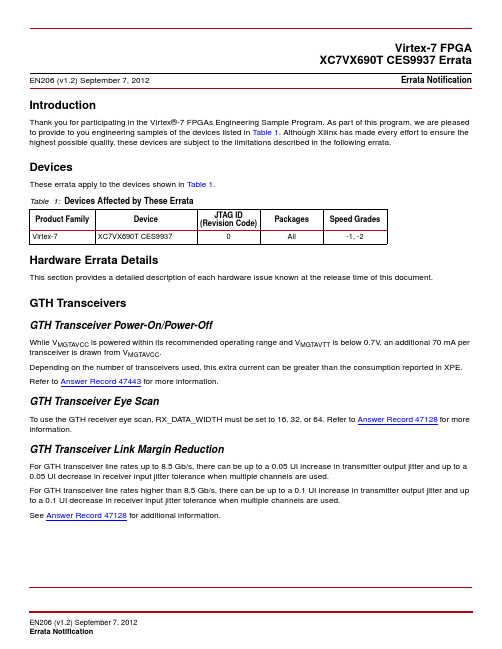
IntroductionThank you for participating in the Virtex®-7 FPGAs Engineering Sample Program. As part of this program, we are pleased to provide to you engineering samples of the devices listed in T able 1. Although Xilinx has made every effort to ensure the highest possible quality, these devices are subject to the limitations described in the following errata.DevicesThese errata apply to the devices shown in Table 1.Hardware Errata DetailsThis section provides a detailed description of each hardware issue known at the release time of this document.GTH TransceiversGTH Transceiver Power-On/Power-OffWhile V MGTAVCC is powered within its recommended operating range and V MGT AVTT is below 0.7V , an additional 70mA per transceiver is drawn from V MGT AVCC .Depending on the number of transceivers used, this extra current can be greater than the consumption reported in XPE. Refer to Answer Record 47443 for more information.GTH Transceiver Eye ScanTo use the GTH receiver eye scan, RX_DAT A_WIDTH must be set to 16, 32, or 64. Refer to Answer Record 47128 for more information.GTH Transceiver Link Margin ReductionFor GTH transceiver line rates up to 8.5Gb/s, there can be up to a 0.05UI increase in transmitter output jitter and up to a 0.05UI decrease in receiver input jitter tolerance when multiple channels are used.For GTH transceiver line rates higher than 8.5Gb/s, there can be up to a 0.1UI increase in transmitter output jitter and up to a 0.1UI decrease in receiver input jitter tolerance when multiple channels are used.See Answer Record 47128 for additional information.Virtex-7 FPGAXC7VX690T CES9937 ErrataEN206 (v1.2) September 7, 2012Errata NotificationTable 1:Devices Affected by These ErrataProduct Family DeviceJTAG ID (Revision Code)PackagesSpeed GradesVirtex-7XC7VX690T CES9937All-1, -2RXOUTCLK PortFor GTH transceiver line rates higher than 8.5Gb/s, the GTH transceiver RXOUTCLK port, when configured to use the RXOUTCLKPCS or RXOUTCLKPMA path, can exhibit a phase jump of up to 2UI of the line rate.For the following applications:•Buffer use mode: Specify an INPUT_JITTER timing constraint of 2 UI on the RXOUTCLK clock period.•Buffer bypass mode: RXOUTCLK port cannot be used.See Answer Record 47128for additional information.PCIeVirtual Channel CapabilityThe Virtual Channel Capability is always enabled in Configuration Space when the Secondary PCI Express® Capability is enabled.Virtual Channel TC/VC MapThe Virtual Channel Resource Control register TC/VC Map is incorrectly reset to 8'h01 instead of the PCIe Base Specification 3.0 value of 8'hFF.Loopback ExitReset of the LTSSM state machine is required to exit Loopback.Active state in loopback slave mode at Gen3 link speed. Power Budgeting CapabilityThe Power Budgeting Capability is not supported.Resizable BARThe optional PCIe Resizable BAR (RBAR) capability is not supported through configuration. The RBAR feature can be initiated after the FPGA has been configured.End-to-End CRCWhen End-to-End CRC (ECRC) is used with multiple functions (PF0 and PF1 enabled), then ECRC must be enabled for either both functions or neither. It cannot be enabled independently on a per function basis. If only PF0 is used, then ECRC can be enabled or disabled as required.TLP Processing HintsThe TLP Processing Hints (TPH) Completer is not supported.D1 Power StateThe D1 lower power device state is not supported.Root PortRoot Port mode is not supported.AER Header Log OverflowFor the Virtual Function Configuration Space, the optional AER Correctable Error Status register Header Log Overflow Status bit is not supported.Type Condition Bank DDR3DIMM and Component Single Rank HP QDRII+Component Single Rank HP RLDRAMII Component Single Rank HP DDR2DIMM and Component Single Rank HPTraceabilityFigure1 shows an example device top mark for the devices listed in T able1.Figure 1:Example Device Top MarkDate Version Description of Revisions05/02/12 1.0Initial Xilinx release.05/24/12 1.1Added -2 speed grade, Virtual Channel Capability, RXOUTCLK Port, PCIe, and Power BudgetingCapability. Updated Virtual Channel Capability and Design T ool Requirements. Changed ARI CapableHierarchy to Function Level Reset and updated text. Removed Configuration Readback issue becauseit does not affect customer designs.09/07/12 1.2Removed the XADC errata because the specifications were added to DS183,Virtex-7 T and XT FPGAs Data Sheet: DC and Switching Characteristics (v1.4) May 23, 2012. Removedthe recommended sequence from GTH Transceiver Power-On/Power-Off because thespecifications were added to DS183, V irtex-7 T and XT FPGAs Data Sheet: DC andSwitching Characteristics (v1.5) August 3, 2012. Updated GTH Transceiver Link MarginReduction to change units from percentage to UI. Removed MGTAVCC VoltageRequirement errata because the requirement was added to DS183, V irtex-7 T and XTFPGAs Data Sheet: DC and Switching Characteristics (v1.5) August 3, 2012. Updated RootPort. Removed the Physical Interface Rate for Memory Interfaces errata because theoperating condition was added to DS183,Virtex-7 T and XT FPGAs Data Sheet: DC andSwitching Characteristics (v1.4) May 23, 2012.。
Agilent HSMx-C120 C177 C197 C265 高性能片级LED数据手册说明书
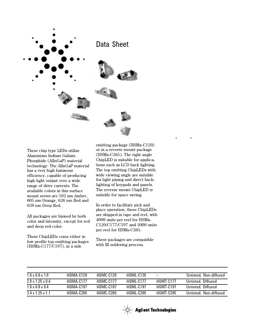
Agilent H SMx-C120/C177/C197/C265High Performance Chip LEDsData SheetFeatures•High brightness AlInGaP material •0805 or 0603 industry standard footprint with 0.4 mm height for top emitting packages•Also available in right angle emitting and reverse mounting packages•Diffused optics•Operating temperature range of –30°C to +85°C•Compatible with IR soldering •Available in 4 colors•Available in 8 mm tape on 7"diameter reel•Reel sealed in zip locked moisture barrier bags Applications•Membrane switch indicator •LCD backlighting•Push button backlighting •Front panel indicator •Symbol backlighting •Keypad backlighting •Microdisplays•Small message panel signageDescriptionThese chip type LEDs utilize Aluminium Indium Galium Phosphide (AlInGaP) material technology. The AlInGaP material has a very high luminousefficiency, capable of producing high light output over a wide range of drive currents. The available colors in this surface mount series are 592 nm Amber,605 nm Orange, 626 nm Red and 639 nm Deep Red.All packages are binned by both color and intensity, except for red and deep red color.These ChipLEDs come either in low profile top emitting packages (HSMx-C177/C197), in a sideemitting package (HSMx-C120)or in a reverse mount package (HSMx-C265). The right angle ChipLED is suitable for applica-tions such as LCD back lighting.The top emitting ChipLEDs with wide viewing angle are suitable for light piping and direct back-lighting of keypads and panels.The reverse mount ChipLED is suitable for space saving.In order to facilitate pick and place operation, these ChipLEDs are shipped in tape and reel, with 4000 units per reel for HSMx-C120/C177/C197 and 3000 units per reel for HSMx-C265.These packages are compatible with IR soldering process.Device Selection GuideDimensions (mm)[1,2]Amber RedOrange Deep Red Package Description 1.6 x 0.6 x 1.0HSMA-C120HSMC-C120HSML-C120–Untinted, Non-diffused 2.0 x 1.25 x 0.4HSMA-C177HSMC-C177HSML-C177HSMT-C177Untinted, Diffused 1.6 x 0.8 x 0.4HSMA-C197HSMC-C197HSML-C197HSMT-C197Untinted, Diffused 3.4 x 1.25 x 1.1HSMA-C265HSMC-C265HSML-C265HSMT-C265Untinted, Non-diffusedPackage DimensionsPOLARITYTERMINAL0.40 ± 0.15HSMx-C177POLARITY0.30 ± 0.15TERMINALHSMx-C1970.50 ± 0.15POLARITY0.50 ± 0.15TERMINALHSMx-C265POLARITYTERMINALHSMx-C120NOTES:1. ALL DIMENSIONS IN MILLIMETERS (INCHES).2. TOLERANCE IS ± 0.1 mm (± 0.004 IN.) UNLESS OTHERWISE SPECIFIED.Absolute Maximum Ratings at T A = 25˚CParameter HSMx-Cxxx UnitsDC Forward Current [1]25mAPeak Pulsing Current[2]100mAPower Dissipation60mWReverse Voltage (I R = 100 µA)5VLED Junction Temperature95˚COperating Temperature Range–30 to +85˚CStorage Temperature Range–40 to +85˚CSoldering Temperature See reflow soldering profile (Figures 8 & 9)Notes:1. Derate linearly as shown in Figure 4.2. Pulse condition of 1/10 duty and 0.1 ms width.Electrical Characteristics at T A = 25˚CForward Voltage Reverse Breakdown Capacitance C ThermalV F (Volts)V R (Volts)(pF), V F = 0,Resistance@ I F = 20 mA@ I R = 100 µA f = 1 MHz RθJ–PIN(˚C/W) Part Number Typ.Max.Min.Typ.Typ.HSMA-C120 1.9 2.4511400HSMA-C177/197 1.9 2.4511300HSMA-C265 1.9 2.4511550HSMC-C120 1.9 2.4515400HSMC-C177/197 1.9 2.4515300HSMC-C265 1.9 2.4515550HSML-C120 1.9 2.4520400HSML-C177/197 1.9 2.4520300HSML-C265 1.9 2.4520550HSMT-C177/197 1.9 2.4515300HSMT-C265 1.9 2.4515550V F Tolerance: ± 0.1 VOptical Characteristics at T A = 25˚CLuminous Color,Viewing LuminousIntensity Peak Dominant Angle EfficacyI V (mcd)Wavelength Wavelength 2 θ1/2ηV@ 20 mA[1]λpeak (nm)λd[2](nm)Degrees[3](lm/w) Part Number Color Min.Typ.Typ.Typ.Typ.Typ. HSMA-C120Amber28.590595592155480 HSMA-C177/197Amber28.590595592130480 HSMA-C265Amber28.575595592150480 HSMC-C120Red28.590637626155155 HSMC-C177/197Red28.590637626130155 HSMC-C265Red28.575637626150155HSML-C120Orange28.590609605155370HSML-C177/197Orange28.590609605130370HSML-C265Orange28.575609605150370 HSMT-C177/197Deep Red11.23066063913070HSMT-C265Deep Red11.22566063915070Notes:1.The luminous intensity, I V, is measured at the peak of the spatial radiation pattern which may not be aligned with the mechanical axis of the lamp package.2.The dominant wavelength, λd, is derived from the CIE Chromaticity Diagram and represents the perceived color of the device.3.θ1/2 is the off-axis angle where the luminous intensity is 1/2 the peak intensity.Light Intensity (Iv) Bin Limits [1]Intensity (mcd)Bin ID Min.Max.A 0.110.18B 0.180.29C 0.290.45D 0.450.72E 0.72 1.10F 1.10 1.80G 1.80 2.80H 2.80 4.50J 4.507.20K 7.2011.20L 11.2018.00M 18.0028.50N 28.5045.00P 45.0071.50Q 71.50112.50R 112.50180.00S 180.00285.00T 285.00450.00U 450.00715.00V 715.001125.00W 1125.001800.00X 1800.002850.00Y 2850.004500.00Note:1.Bin categories are established for classifica-tion of products. Products may not be avail-able in all categories. Please contact your Agilent representative for information on currently available bins.Amber Color Bins [1]Dom. Wavelength (nm)Bin ID Min.Max.A 582.0584.5B 584.5587.0C 587.0589.5D 589.5592.0E 592.0594.5F594.5597.0Orange Color Bins [1]Dom. Wavelength (nm)Bin ID Min.Max.A 597.0600.0B 600.0603.0C 603.0606.0D 606.0609.0E 609.0612.0F612.0615.0Tolerance: ± 0.5 nmNote:1. Bin categories are established for classification of products. Products may not be available in all categories. Please contact your Agilent representative for information on currently available bins.Tolerance: ± 1 nmTolerance: ± 15%Color Bin LimitsFigure 4. Maximum forward current vs.ambient temperature.Figure 3. Luminous intensity vs. forward current.I F – FORWARD CURRENT – mA00.41.0L U M I N O U S I N T E N S I T Y (N O R M A L I Z E D A T 20 m A )0.60.20.81.41.2Figure 2. Forward current vs. forward voltage.Figure 1. Relative intensity vs. wavelength.WAVELENGTH – nmR E L A T I V E I N T E N S I T Y – %500550600650700100101V F – FORWARD VOLTAGE – VI F – F O R W A R D C U R R E N T – m AI F M A X – M A X I M U M F O R W A R D C U R R E N T – m AT A – AMBIENT TEMPERATURE – °CFigure 5. Relative intensity vs. angle for HSMx-C120.100908070605040302010R E L A T I V E I N T E N S I T Y-90-80-70-60-50-40-30-20-100102030405060708090ANGLE100908070605040302010R E L A T I V E I N T E N S I T Y-90-80-70-60-50-40-30-20-100102030405060708090ANGLEFigure 6. Relative intensity vs. angle for HSMx-C177/197.Figure 9. Recommended Pb-free reflow soldering profile.Figure 10. Recommended soldering pattern for HSMx-C177.R E L A T I V E I N T E N S I T Y – %1000ANGLE806050702010304090-70-50-3002030507090-90-20-80-60-40-1010406080(0.035)0.8 (0.028)BOARDFigure 11. Recommended soldering pattern for HSMx-C197.Figure 7. Relative intensity vs. angle for HSMx-C265.R E L A T I V E I N T E N S I T Y – %1000ANGLE806050702010304090-70-50-3002030507090-90-20-80-60-40-1010406080NOTE:1. ALL DIMENSIONS IN MILLIMETERS (INCHES).TIMET E M P E R A T U R E* THE TIME FROM 25 °C TO PEAK TEMPERATURE = 6 MINUTES MAX.Figure 8. Recommended reflow soldering profile.T E M P E R A T U R EFigure 14. Reeling orientation.Figure 15. Reel dimensions.Figure 12. Recommended soldering pattern for HSMx-C120.Figure 13. Recommended soldering pattern for HSMx-C265.(0.031)(0.031)(0.047)Ø 20.20 MIN. (Ø 0.795 MIN.)Ø 13.1 ± 0.5 NOTE:1. ALL DIMENSIONS IN MILLIMETERS (INCHES).Figure 16. Tape dimensions.TABLE 1DIMENSIONS IN MILLIMETERS (INCHES)DIM. A ± 0.10 (0.004)DIM. B ± 0.10 (0.004)PART NUMBER DIM. C ± 0.10 (0.004)HSMx-C120 SERIES HSMx-C177 SERIES HSMx-C197 SERIES(0.020 ± 0.002)0.80 (0.031) 0.60 (0.024) 0.60 (0.024)1.90 (0.075)2.30 (0.091) 1.80 (0.071) 1.15 (0.045) 1.40 (0.055) 0.95 (0.037)NOTES:1. ALL DIMENSIONS IN MILLIMETERS (INCHES).2. TOLERANCE IS ± 0.1 mm (± 0.004 IN.) UNLESS OTHERWISE SPECIFIED.HSMx-C265 SERIES 3.70 (0.146) 1.45 (0.057) 1.30 (0.051)TABLE 1DIMENSIONS IN MILLIMETERS (INCHES)DIM. A ± 0.10 (0.004)DIM. B ± 0.10 (0.004)PART NUMBERDIM. C ± 0.10 (0.004)/semiconductorsFor product information and a complete list of distributors, please go to our web site.For technical assistance call:Americas/Canada: +1 (800) 235-0312 or (916) 788-6763Europe: +49 (0) 6441 92460China: 10800 650 0017Hong Kong: (+65) 6756 2394India, Australia, New Zealand: (+65) 6755 1939Japan: (+81 3) 3335-8152(Domestic/Interna-tional), or 0120-61-1280(Domestic Only)Korea: (+65) 6755 1989Singapore, Malaysia, Vietnam, Thailand,Philippines, Indonesia: (+65) 6755 2044Taiwan: (+65) 6755 1843Data subject to change.Copyright © 2004 Agilent Technologies, Inc.Obsoletes 5988-5501EN April 22, 20045989-0551ENConvective IR Reflow Soldering For more information on IR reflow soldering, refer toApplication Note 1060, Surface Mounting SMT LED Indicator Components .Storage Condition:5 to 30°C @ 60% RH max.Baking is required under the condition:a) the blue silica gel indicator becoming white/transparent colorb) the pack has been open for more than 1 weekBaking recommended condition:60 ± 5°C for 20 hours.Figure 17. Tape leader and trailer dimensions.END STARTSEALED WITH COVER TAPE.SEALED WITH COVER TAPE.OF CARRIER AND/ORCOVER TAPE.。
中微半导体 BAT32G133 32位微控制器 数据手册说明书
BAT32G133 数据手册ArrayBAT32G133数据手册基于ARM® Cortex®-M0+的超低功耗32位微控制器内置32K字节Flash,丰富的模拟功能,定时器及各种通讯接口请注意以下有关CMS知识产权政策*中微半导体(深圳)股份有限公司(以下简称本公司)已申请了专利,享有绝对的合法权益。
与本公司MCU或其他产品有关的专利权并未被同意授权使用,任何经由不当手段侵害本公司专利权的公司、组织或个人,本公司将采取一切可能的法律行动,遏止侵权者不当的侵权行为,并追讨本公司因侵权行为所受的损失、或侵权者所得的不法利益。
*中微半导体(深圳)股份有限公司的名称和标识都是本公司的注册商标。
*本公司保留对规格书中产品在可靠性、功能和设计方面的改进作进一步说明的权利。
然而本公司对于规格内容的使用不负责任。
文中提到的应用其目的仅仅是用来做说明,本公司不保证和不表示这些应用没有更深入的修改就能适用,也不推荐它的产品使用在会由于故障或其它原因可能会对人身造成危害的地方。
本公司的产品不授权适用于救生、维生器件或系统中作为关键器件。
本公司拥有不事先通知而修改产品的权利,对于最新的信息,请参考官方网站。
功能⚫超低功耗工作环境:➢电源电压范围:2.0V到5.5V➢温度范围:-40℃到105℃➢低功耗模式:睡眠模式,深度睡眠模式➢运行功耗:35uA/MHz@64MHz➢深度睡眠模式下功耗:0.45uA➢深度睡眠模式+32.768K+RTC工作:0.7uA⚫内核:➢ARM®32-bitCortex®-M0+ CPU➢工作频率:32KHz~64MHz⚫存储器:➢32KB Flash存储器,程序与数据存储共享(支持Byte/HalfWord/Word编程)➢ 1.5KB 专用数据Flash存储器➢4KB SRAM存储器,附带奇偶校验⚫电源和复位管理:➢内置上电复位(POR)电路➢内置电压检测(LVD)电路(门限电压可设)⚫时钟管理:➢外部高速晶振1MHz~20MHz➢外部低速晶振32.768KHz➢内部高速时钟1MHz~64MHz➢内部低速时钟15KHz/30KHz可选⚫乘法器模块:➢乘法器:支持32bit乘法运算⚫增强型DMA控制器:➢中断触发启动。
FPGA可编程逻辑器件芯片XC7VX690T-1FF1761C中文规格书

Table 65: GTY Transceiver Dynamic Reconfiguration Port (DRP) Switching CharacteristicsSymbol Description All Speed Grades Units F GTYDRPCLK GTYDRPCLK maximum frequency250MHzTable 66: GTY Transceiver Reference Clock Switching CharacteristicsSymbol Description ConditionsAll Speed GradesUnits Min Typ MaxF GCLK Reference clock frequency range60–820MHzT RCLK Reference clock rise time20% – 80%–200–psT FCLK Reference clock fall time80% – 20%–200–psT DCREF Reference clock duty cycle Transceiver PLL only405060%Kintex UltraScale+ FPGAs Data Sheet: DC and AC Switching CharacteristicsDS922 (v1.17) February 16, 2021Product SpecificationTable 67: GTY Transceiver Reference Clock Oscillator Selection Phase Noise MaskSymbol Description1, 2OffsetFrequency Min Typ Max UnitsQPLL REFCLKMASK QPLL0/QPLL1 reference clock select phase noisemask at REFCLK frequency = 156.25 MHz 10 kHz–––112dBc/Hz 100 kHz–––1281 MHz–––145QPLL0/QPLL1 reference clock select phase noise mask at REFCLK frequency = 312.5 MHz 10 kHz–––103dBc/Hz 100 kHz–––1231 MHz–––143QPLL0/QPLL1 reference clock select phase noise mask at REFCLK frequency = 625 MHz 10 kHz–––98dBc/Hz 100 kHz–––1171 MHz–––140CPLL REFCLKMASK CPLL reference clock select phase noise mask atREFCLK frequency = 156.25 MHz 10 kHz–––112dBc/Hz 100 kHz–––1281 MHz–––14550 MHz–––145CPLL reference clock select phase noise mask at REFCLK frequency = 312.5 MHz 10 kHz–––103dBc/Hz 100 kHz–––1231 MHz–––14350 MHz–––145CPLL reference clock select phase noise mask at REFCLK frequency = 625 MHz 10 kHz–––98dBc/Hz 100 kHz–––1171 MHz–––14050 MHz–––144Notes:1.For reference clock frequencies not in this table, use the phase-noise mask for the nearest reference clock frequency.2.This reference clock phase-noise mask is superseded by any reference clock phase-noise mask that is specified in a supported protocol,e.g., PCIe.Table 68: GTY Transceiver PLL/Lock Time AdaptationSymbol Description ConditionsAll Speed GradesUnits Min Typ MaxT LOCK Initial PLL lock.––1msT DLOCK Clock recovery phase acquisition andadaptation time for decision feedbackequalizer (DFE)After the PLL is locked to thereference clock, this is thetime it takes to lock the clockdata recovery (CDR) to thedata present at the input.–50,00037 x 10⁶UIClock recovery phase acquisition and adaptation time for low-power mode (LPM) when the DFE is disabled –50,000 2.3 x 10⁶UIKintex UltraScale+ FPGAs Data Sheet: DC and AC Switching CharacteristicsDS922 (v1.17) February 16, 2021Product Specification。
FPGA可编程逻辑器件芯片XC7Z035-2FBG676E中文规格书
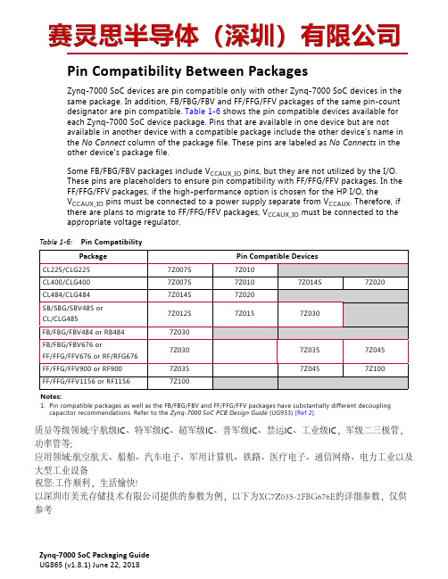
Pin Compatibility Between PackagesZynq-7000SoC devices are pin compatible only with other Zynq-7000SoC devices in thesame package. In addition, FB/FBG/FBV and FF/FFG/FFV packages of the same pin-countdesignator are pin compatible. Table1-6 shows the pin compatible devices available foreach Zynq-7000SoC device package. Pins that are available in one device but are notavailable in another device with a compatible package include the other device's name inthe No Connect column of the package file. These pins are labeled as No Connects in theother device's package file.Some FB/FBG/FBV packages include V CCAUX_IO pins, but they are not utilized by the I/O.These pins are placeholders to ensure pin compatibility with FF/FFG/FFV packages. In theFF/FFG/FFV packages, if the high-performance option is chosen for the HP I/O, theV CCAUX_IO pins must be connected to a power supply separate from V CCAUX. Therefore, ifthere are plans to migrate to FF/FFG/FFV packages, V CCAUX_IO must be connected to theappropriate voltage regulator.Table 1-6:Pin CompatibilityPackage Pin Compatible DevicesCL225/CLG2257Z007S7Z010CL400/CLG4007Z007S7Z0107Z014S7Z020CL484/CLG4847Z014S7Z020SB/SBG/SBV485 or7Z012S7Z0157Z030CL/CLG485FB/FBG/FBV484 or RB4847Z030FB/FBG/FBV676 or7Z0307Z0357Z045FF/FFG/FFV676 or RF/RFG676FF/FFG/FFV900 or RF9007Z0357Z0457Z100FF/FFG/FFV1156 or RF11567Z100Notes:1.Pin compatible packages as well as the FB/FBG/FBV and FF/FFG/FFV packages have substantially different decouplingcapacitor recommendations. Refer to the Zynq-7000 SoC PCB Design Guide (UG933) [Ref2].质量等级领域:宇航级IC、特军级IC、超军级IC、普军级IC、禁运IC、工业级IC,军级二三极管,功率管等;应用领域:航空航天、船舶、汽车电子、军用计算机、铁路、医疗电子、通信网络、电力工业以及大型工业设备祝您:工作顺利,生活愉快!以深圳市美光存储技术有限公司提供的参数为例,以下为XC7Z035-2FBG676E的详细参数,仅供参考Chapter 1:Package OverviewFlip-Chip PackagesFor larger Zynq-7000SoC devices, Xilinx offers the flip-chip BGA packages, which present a low thermal path. These packages incorporate a heat spreader with additional thermal interface material (TIM), as shown in Figure5-4.3.Preheat dwell 95–180°C for 120–180 seconds4.IR reflow must be performed on dry packagesPb-Free Reflow SolderingXilinx uses SnAgCu solder balls for BGA packages. In addition, suitable material are qualified for the higher reflow temperatures (250°C maximum, 260°C for dry rework only) required by Pb-free soldering processes.Xilinx does not recommend soldering SnAgCu BGA packages with SnPb solder paste using a Sn/Pb soldering process. Traditional Sn/Pb soldering processes have a peak reflow temperature of 220°C. At this temperature range, the SnAgCu BGA solder balls do not properly melt and wet to the soldering surfaces. As a result, reliability and assembly yields can be compromised.The optimal profile must take into account the solder paste/flux used, the size of the board, the density of the components on the board, and the mix between large components and smaller, lighter components. Profiles should be established for all new board designs using thermocouples at multiple locations on the component. In addition, if there is a mixture of devices on the board, then the profile should be checked at various locations on the board. Ensure that the minimum reflow temperature is reached to reflow the larger components and at the same time, the temperature does not exceed the threshold temperature that might damage the smaller, heat sensitive components.Table5-2 and Figure5-7 provide guidelines for profiling Pb-free solder reflow.In general, a gradual, linear ramp into a spike has been shown by various sources to be the optimal reflow profile for Pb-free solders (Figure5-7). SAC305 alloy reaches full liquidus temperature at 235°C. When profiling, identify the possible locations of the coldest solder joints and ensure that those solder joints reach a minimum peak temperature of 235°C for at least 10 seconds. It might not be necessary to ramp to peak temperatures of 260°C and above. Reflowing at high peak temperatures of 260°C and above can damage the heat sensitive components and cause the board to warp. Users should reference the latest IPC/JEDEC J-STD-020 standard for the allowable peak temperature on the component body. The allowable peak temperature on the component body is dependent on the size of the component. Refer to Table5-2 for peak package reflow body temperature information. In any case, use a reflow profile with the lowest peak temperature possible.Table 5-2:Pb-Free Reflow Soldering GuidelinesProfile Feature Convection, IR/ConvectionRamp-up rate2°C/s maximumPreheat Temperature 150°–200°C60–120 secondsTemperature maintained above 217°C60–150 seconds (60–90 seconds typical)Time within 5°C of actual peak temperature30 seconds maximum。
分析芯片数据手册说明书

ADCMP350YKSZ-REEL7ADCMP356YKSZ-REEL7Rev. BInformation furnished by Analog Devices is believed to be accurate and reliable. However, noresponsibility is assumed by Analog Devices for its use, nor for any infringements of patents or other rights of third parties that may result from its use. Specifications subject to change without notice. No license is granted by implication or otherwise under any patent or patent rights of Analog Devices. T rademarks and registered trademarks are the property of their respective owners. One Technology Way, P.O. Box 9106, N orwood, MA 02062-9106, U.S.A. Tel: 781.329.4700 Fax: 781.461.3113 ©2004–2011 Analog Devices, Inc. All rights reserved.FEATURESComparators with 0.6 V on-chip referencesOutput stagesOpen-drain active low (ADCMP350)Open-drain active high (ADCMP354)Push-pull active high (ADCMP356)High voltage (up to 22 V) tolerance on VINand open-drain output pinsLow power consumption: 10 µA10 nA input bias current15 mV hysteresis5 µs propagation delaySpecified over −40°C to +125°C temperature range4-lead SC70 packageAPPLICATIONSVoltage detectorsMicroprocessor systemsComputersBattery monitorsIntelligent instrumentsPortable equipmentFUNCTIONAL BLOCK DIAGRAM(OD)VV IN5112-1Figure 1. ADCMP350 Functional Block Diagram(OD/PP)VV IN5112-21 Figure 2. ADCMP354/ADCMP356 Functional Block DiagramGENERAL DESCRIPTIONThe ADCMP350/ADCMP354/ADCMP356 are comparator and reference circuits suitable for use in general-purpose applications. The high voltage input and output structures allow voltages of up to 22 V on the input of all devices and the output of the open-drain devices. High performance over the −40°C to +125°C temperature range makes them suitable for use in automotive and other thermally harsh applications, while low power consumption and space-efficient SC70 packaging make them ideal for battery-powered portable equipment.Rev. B | Page 2 of 12TABLE OF CONTENTSFeatures .............................................................................................. 1 Applications ....................................................................................... 1 Functional Block Diagram .............................................................. 1 General Description ......................................................................... 1 Revision History ............................................................................... 2 Specifications ..................................................................................... 3 Absolute Maximum Ratings ............................................................ 4 ESD Caution .................................................................................. 4 Pin Configuration and Function Descriptions ..............................5 Typical Performance Characteristics ..............................................6 Applications Information .................................................................9 Adding Hysteresis..........................................................................9 Voltage Detector ............................................................................9 Outline Dimensions ....................................................................... 10 Ordering Guide .. (10)REVISION HISTORY4/11—Rev. A to Rev. BDeleted ADCMP352 .......................................................... U niversal Changes to Adding Hysteresis Section, Figure 20, andFigure 21 (9)11/09—Rev. 0 to Rev. AChanges to Ordering Guide (10)10/04—Revision 0: Initial VersionSPECIFICATIONSV CC = full operating range, T A = −40°C to +125°C, unless otherwise noted.Rev. B | Page 3 of 12Rev. B | Page 4 of 12ABSOLUTE MAXIMUM RATINGST A = 25°C, unless otherwise noted.Stresses above those listed under Absolute Maximum Ratings may cause permanent damage to the device. This is a stress rating only; functional operation of the device at these or any other conditions above those indicated in the operationalsection of this specification is not implied. Exposure to absolute maximum rating conditions for extended periods may affect device reliability.Rev. B | Page 5 of 12PIN CONFIGURATION AND FUNCTION DESCRIPTIONS4ADCMP350/ADCMP354/ADCMP356GND OUTV CCV IN13205112-002Figure 3. Pin ConfigurationRev. B | Page 6 of 12TYPICAL PERFORMANCE CHARACTERISTICS7.07.58.08.59.09.510.010.511.02.25 2.55 2.85 3.15 3.45 5.55V CC (V)I C C (µA )05112-0033.754.05 4.35 4.65 4.955.25Figure 4. I CC vs. V CC over Temperature500540560580600620640660680700–40–25–105203550658095110125TEMPERATURE (°C)V TR I P (m V )05112-004520Figure 5. V IN Trip Threshold vs. Temperature (V CC = 3.3 V)0468101214161820–40–25–105203550658095110125TEMPERATURE (°C)H Y S T ER E S I S (m V )05112-0052Figure 6. V IN Trip Hysteresis vs. Temperature46810121416182********V IN (V)S U P P L Y C U R R E N T (µA )05112-0062101214161820Figure 7. Supply Current vs. Input Voltage (V IN )406080100120140160180200V IN (V)I N L E A K A G E (µA )05112-00720Figure 8. Input Leakage vs. Input Voltage (V IN )05112-019V IN (V)V I N L E A K A G E (µA )Figure 9. V IN Leakage Current vs. V IN Voltage (V CC = 3.8 V)Rev. B | Page 7 of 12110120140150160170180190200I N L E A K A G E (µA )05112-008130V CC (V)100Figure 10. Input Leakage vs. Supply Voltage, V CC (V IN = 22 V)520540580600620640660680700V T R I P (m V )05112-0095602.25 2.55 2.85 3.15 3.45 5.55V CC (V)3.754.05 4.35 4.65 4.955.25500Figure 11. V IN Trip Threshold vs. V CC248101214161820H Y S T E R E S I S (m V )05112-02062.25 2.55 2.85 3.15 3.45 5.55V CC (V)3.754.05 4.35 4.65 4.955.250Figure 12. V IN Trip Hysteresis vs. V CC0.11101001000100000.010.110OUTPUT SINK CURRENT (mA)O U T P U T V O L T A G E (m V )05112-0101Figure 13. Output Voltage vs. Output Sink Current (I SINK = 500 mA)204080100120O U T P U T L O W V O L T A G E (m V )05112-011602.25 2.40 2.703.00 3.30 5.50SUPPLY VOLTAGE (V)3.60 3.904.20 4.50 4.805.200Figure 14. Output Low Voltage vs. Supply Voltage (I SINK = 500 mA)204080100120140160180200F A L L T I M E (n s )05112-012602.25 2.40 2.70 3.00 3.30 5.50SUPPLY VOLTAGE (V)3.60 3.904.20 4.50 4.805.200Figure 15. Fall Time vs. Supply VoltageRev. B | Page 8 of 121020405060708090100S H O R T -C I R C U I T S I N K C U R R E N T (m A )05112-013302.25 2.40 2.70 3.00 3.30 5.50SUPPLY VOLTAGE (V)3.60 3.904.20 4.50 4.805.200Figure 16. Short-Circuit Sink Current vs. Supply Voltage(V CC = 3.3 V, Push-Pull Only)5152025108090100110130INPUT OVERDRIVE (mV)P R O P A G A T I O N D E L A Y (µs )05112-01410120706*********Figure 17. Propagation Delay vs. Input Overdrive (V CC = 3.3 V, Push-Pull Only)05112-015Figure 18. Propagation Delay Timing, 10 mV Overdrive05112-016Figure 19. Propagation Delay Timing, 100 mV OverdriveRev. B | Page 9 of 12APPLICATIONS INFORMATIONADDING HYSTERESISTo prevent oscillations at the output caused by noise or slowly moving signals passing the switching threshold, positive feedback can be used to add hysteresis to the noninverting parts (ADCMP354 and ADCMP356).For the noninverting configuration shown in Figure 20, two resistors are used to create different switching thresholds,depending on whether the input signal is increasing or decreasing in magnitude. When the input voltage is increasing, the threshold is above V REF , and when it is decreasing, the threshold is below V REF . The upper input threshold level is given by()PULLUPCC PULLUP R R2R1V R R2R1+−++=REF IN_HI V Vwhere V REF = 0.6 V , assuming R LOAD >> R2, R PULLUP The lower input threshold level is given by()R2R2R1V V REF IN_LO +=The hysteresis is the difference between these voltage levels and is given byPULLUPR R2R1+=∆CC IN V VLOADV IN05112-022Figure 20. Noninverting Comparator Configuration with Added HysteresisVOLTAGE DETECTORThe ADCMP350/ADCMP354/ADCMP356 can be used to monitor voltages, such as battery monitoring or threshold detectors. Using a resistor divider at the input to select the appropriate trip voltage, the comparator can be configuredto give a logic output when the input passes that threshold. Figure 21 shows the typical configuration of the ADCMP354 for monitoring a supply to indicate that the voltage is above a certain level.V IN05112-023Figure 21. Voltage Detector ApplicationRev. B | Page 10 of 12OUTLINE DIMENSIONS*PACKAGE OUTLINE CORRESPONDS IN FULL TO EIAJ SC82EXCEPT FOR WIDTH OF PIN 2AS SHOWN.072809-AFigure 22. 4-Lead Thin Shrink Small Outline Transistor Package [SC70](KS-4)Dimensions shown in millimeters1Z = RoHS Compliant Part.NOTESRev. B | Page 11 of 12Rev. B | Page 12 of 12NOTES©2004–2011 Analog Devices, Inc. All rights reserved. Trademarks and registered trademarks are the property of their respective owners.D05112-0-4/11(B)ADCMP350YKSZ-REEL7ADCMP356YKSZ-REEL7。
SWCG9723A 锂离子电池充电器 Datasheet说明书

and Reliable Chargering General DescriptionThe SWCG9723A is a compact and efficient Lithium ion(Li+) or Lithium ion polymer (Li+/polymer) battery charger. It can provide power and charge the signle cell battery of a system typically found in compact portable device. An internal switching buck converter regulates the supply input for charging the battery and powering the system even if the battery is absent. The converter can also operate as a simple pass-through switch with no switching if the load and input voltages are close.A typical application circuit is shown in Figure 2. The SWCG9723A features resistor programmable constant current and constant voltage charging capability plus a charge limiting timer and operates in compliance with the BAJ/JEITA safety guide. An NTC (β=3950K) can be used for battery temperature sensing on top of the internal junction temperature sensing on top of the internal junction temperature monitoring. The IND status output pin can be connected to LEDs to indicate the operating conditions,such as power input ok(POK), in charging(CHG), VIN over-voltage(POK and CHG alternate blinking) and no power/disabled (OFF). Voltage fold-back on the output is provided to power the system from the input while retaining battery charge and prventing overcharge. Input under-voltage regulation is implemented by reducing the load current such that VIN stays above a minimum when the source is weak. Similarly,the die temperature can be regulated and limited by reducing output power to avoid device or the circuit SWCG9723ACompact Switch Li+/Poly Battery Charger Safe board being overheated.These features simplify the system design and ensure safe and reliable operation as well as improved user experience.The SWCG9723A is delivered in a Green TDFN-2X3-8BL package. The device operates in -40'C to +85'C two two thermal regulation options for +55'C or for +115'C.Features Applications˙Constant Current, Constant Voltage(CCCV)˙Powering and Charge Control ofCharging with Floating Time-Out TimerSystems with 500mAh to 6000mAh ˙Maximum 2.3A Charging for 4.2V to 4.5V Battery Li+/Polymer Batteries˙1.34MHz Switching Frequency˙Programmable Charge Voltage and Current˙4.15V input Voltage Regulation Package˙Output Voltage Fold-Back Charge Retaining ˙TDFN-2X3-8BL˙Thermal Regulation Optins˙Typical Peak Efficiency of 92% at 1.5A, V IN =5V ˙-40'C to +85'C Operating Temperature RangeTDFN-2X3-8BLFigure 1. Package Type of SWCG9723AStar-wingPin ConfigurationFigure 2. Pin Configuration of SWCG9723A (Top View )Pin Function TableTDFN2X3-8BL Pin Name TYPE1SW O 2IND O 3CVICharge current Programming/Charge-Inhibit Input Pin. Connect a resistor between this pin and GND to program the constant chargeSWCG9723APin FunctionBuck Converter Switching Node. Connect to the output inductor Status Indication Output. It can source or sink constant current when powered (Charging or not charging). It can only sink current if no power is applied.Charge Voltage Programming Input Pin. Connect a resistor between this pin and ground to select one of the 7 charging voltages.4CC I5VBAT I 6NTC I 7VIN P 8GND G Exposed PadEPICFunctional Block Diagramcurrent I CC . (R CCSET =K/I CC ). Pull up this pin to a voltage higher than V INH to inhibit and stop charging.Battery Voltage Sense Input.NTC Temperature Sensing Input. Connect to an NTC thermistor (β=3950K) with other end grounded and biased to VIN by a 1.5XR NTC25'C resistor. Ground thois pin if NTC is not used.Power Input Pin.Ground Reference Pin.Exposed Pad. Thermal pad is internally grounded and must be connected to the PCB GND plane.Figure 3. Pin Configuration of SWCG9723A (Top View )Star-wingOrdering InformationOrdering CodeMarking IDnote ACBAXXnote A: XX = Date Code and Vendor Code.Absolute Maximum Ratings Note 1Unit V V TDFN2X3-8BLmW SWCG9723AParameterSymbol Value Input Supply Voltage(V VBAT =4V)V IN 6BAT Pin Voltage (V IN Open)V BAT 6450Maximum Power Dissipation P D SWCG9723A-4V2TDN3BLTR-40'C to +85'CTDFN2X3-8BL3000pcs/TRSWCG9723APart NumberTemperature Range Package Quantity per Reel Circuit TypeTR : Tape and Reel Package Types:TDN3BL: TDFN2X3-8BL Voltage: 4V2: 4.2V'C 'C 'C TDFN2X3-8BL 'C/W V V V VRecommend Operating Conditions note1V A 'C 'CNote 1: the "Absolute maximum Ratings" is rated values exceeding which the product could suffer physical damage. These values must therefore not be exceeded under any conditions.2: This integrated circuit can be damaged by ESD if you don't pay attention to ESD protection.Supply Voltage Range 3.5 to 5.5V MAX 100090Package Thermal ResistanceQ JA CDM Surge TestESD SusceptibilityHMB, Any Pin to Ground and Power CDMHBM 4000Operating Junction Temperature T J +150Lead Temperature (Soldering, 10s)T LEAD 260Storage Temperature Range T STG -65 to +150Environmental Temperature RangeT OPR-40 to +85Operating Junction Temperature Range T OJT Charge Current Setting RangeI BAT 0.3 to 2.3-40 to +125V ISD Input Over-Voltage Clamp (50mA, 24 hours)Input Surge DischargeV OVC811Electrical Characteristics( V IN =5V, V VBAT =3.8V Full=-40'C to +85'C typical values at T J =25' unless otherwise specified )Symbol Min Type MaxUnitV OVP5.51 5.67 5.84V V CHGm 3.90 4.04 4.17V I Q -1520uA I LKGFLD -0.1 1.5uA I LKG-0.11.5uAV CHG 4.175 4.20 4.225V V STEP -50-mV V DROPm 2.02040mV V DROPM 120170230mV V DEG -50-mV I DEG 273033%DT1616366%DT2555860%DT3202325%DT4151719%V FLT 96.498.099.5%FR 96.797.197.7%V RR 93.995.597.1%I PRE 6597130mA V PRE 566065%I LPCG -300-mA t LPCG 4.055.005.83mS K 91501000010800V V INH - 1.5-V ICC0.9151.001.08ANote 2. Parameters guaranteed by product characterization.ParameterTest Condition Over-Voltage Protection Threshold Minimum Input Operation Voltage V BAT open, V VIN =5V to 6VV BAT open, V VIN =5V to 4V VIN Supply CurrentIND open, fold-back mode,R CV =1KΩ, set V VBAT =4.17V, no switchingR CC =10KΩ, K=I CC XR CCSETFast Charge CurrentR CC =10KΩ, V VBAT =3.8V, V VIN =5V Charge Inhibition Voltage Threshold Charge Current Setting Ratio Voltage forcing on the CC pin to inhibit chargingLoad Pre-charge Period 10'C Threshold note2As percentage of V CHG 45'C Threshold note2Floating Charge Timer Start Threshold Load Pre-charge Current When power-up at V VBAT <60%XV CHGV IN =5V, V VBAT <60%XV CHG Recharge ThresholdBattery Precondition Charge Current Battery Precondition Threshold Voltage Charge Voltage Fold-Back when NTC Temperature is out of 10'C to 45'C Range As percentage of V CHG As percentage of V CHG As percentage of V IN As percentage of V CHG As percentage of V IN As percentage of V IN Compare with V CHG in 10'C to 45'C NTC temperature range Charge Current Decrease at NTC Temperature Regulation note2As percentage of I CC in 10'C to 45'C NTC temperature range 5'C Threshold note2As percentage of V IN 55'C Threshold note2Float-Back Retaining Output Voltage Fold-back mode, R CV =1KΩ, set V VBAT =4.17V, no switching VIN open, V VBAT =3V to 4.5VLeakage Current into the V BATnote2Charg LoopSwitch charge mode, input voltage is greater than V CHGm The Minimum Voltage Drop between V IN and V BAT Required for Switch ChargingLDO charge mode, input voltage is greater than V CHGmCV pin connected to GND-Charge Output Regulation Voltage Charge Voltage StepElectrical Characteristics(Con.)( V IN =5V, V VBAT =3.8V Full=-40'C to +85'C typical values at T J =25' unless otherwise specified )Symbol Min Type MaxUnitI RES 85140190mA t FCOT 7492108min V INREG 3.98 4.15 4.32V T OTR -115-'C T SHUT-155-'C T SHUT_HYST -20-'C t MON155192224msR DS(ON)-H -140200mΩR DS(ON)-L -120180mΩI PEAK - 3.2-A f S1.081.341.56MHzI INDSNK 0.4 1.3 2.5mA I INDSRC 0.4 1.3 2.5mA I BLINK155192224mSNote 2. Parameters guaranteed by product characterization.IND Source Current note2V VIN =5V IND Blink Period note2Input OVP statePWM Switching Frequency-IND Sink Current note2V VIN =5V Indication DrivingHigh-side Switch MOSFET On-Resistance between VIN and SW -Low-side Switch MOSFET On-Resistance between SW and GND -Peak Current Limit -Thermal Shutdown Temperature Temperature increasingThermal Shutdown Hysteresis -BAT Voltage Monitoring Period before Turning into Fold-Back Switch Operation-Input Voltage Regulation Threshold V VBAT =3.8V, V IN for making charge current to 0Thermal Regulation Threshold note2-ParameterTest ConditionCharge Termination Current Threshold -Floating Charge Termination Time -Typical Performance Characteristics(V VIN=5V, V VBAT=3.8V, T J=25'C, unless otherwise noted.)Typical Performance Characteristics (Con.) (V VIN=5V, V VBAT=3.8V, T J=25'C, unless otherwise noted.)Essential SequenceStar-wingTypical Application CircuitsProgrammed for charge Current of I CC =1.47A and Voltage of V CHG =4.2VFigure 6. Typical Application CircuitSWCG9723ATable 1. Bill of Materials for Typical Application CircuitQuantitySizeMaker1TDFN-2X3-8BL Star-wing 1 5.0X5.0X2.0mm iWAS20603SAMSUMG 10603Uniohm 10603Uniohm 20603Uniohm 10603Uniohm10603SunlordFigure 7. Programmed for charge Current of I CC =1.47A and Voltage of V CHG =4.2VDesignatorPart NumberDescriptionU1L1C1, C2R1R2R3, R4R5R6Ind, 2.2uH, Irms=5.0A, Isat=6.5A,DCR=30mΩCap, Cerm, 10uF, 10V, X5R Res, 0Ω, 1%Res, 6.8KΩ, 1%Res, 3.3KΩ, 1%Res, 15KΩ, 1%NTC, 10KΩ, 1%, β=3950K SWCG9723AiSAB0518-2R2M SDNT1608X103F3950FTFSwitch Li+/Poly Battery Charger20603NationstarLED1, LED2Chip Light Emitting Diode, BlueFC-DA1608BK-470H10Function Description and ApplicationFunction Description and Application(Con.)Star-wing Mechanical DimensionsSWCG9723A PKG: TDFN2X3-8BL ( TDN3BL )。