新一代蜂群恒温加热器
eQ-3 CC-RT-M-BLE-EQ 蓝牙智能散热器恒温器使用说明书

Operating ManualBLUETOOTH SmartRadiator ThermostatUKCC-RT-M-BLE-EQDocumentation © 2018 eQ-3 AG, GermanyAll rights reserved.Translation from the original version in German.153855Version 1.0 (05/2018)1. Information about this manualPlease read this manual completely and carefully before starting touse the device. The manual contains important information about theintended use of the device. Especially observe the safety notes. Keepthe manual for later consultation. If you hand over the device to otherpersons for use, please hand over this manual as well.Symbols used:Attention! This indicates a hazard.Note. This section contains important additional information.2. Package contents1x radiator thermostat1x adapter Danfoss RA1x adapter Danfoss RAV1x spigot extension Danfoss RAV1x adapter Danfoss RAVL1x support ring1x nut M41x cylinder head screw M4 x 12 mm2x 1.5 V mignon/LR6/AA2x operating manual (English and German)3. Device overviewA Bar chart of programmed heating phasesB Eco/comfort temperature (), open-window function(), manual mode (Manu), automatic mode (Auto)C Holiday function (), week day, empty battery symbol()D Mode/Menu button: Switch between auto mode, manu modeand holiday function (press button briefly); open setup menu(press button for at least 3 seconds)E Control wheel: Change settings, e.g. temperature (turn the con-trol wheel), activate the boost function and confirm/save set-tings in the menu (press control wheel briefly)F Union nut for fitting on the heating valveG Display of temperature, time and date, menu options, functionsH button: Switch between eco and comforttemperature4. FunctionThe electric BLUETOOTH® Smart Radiator Thermostat offers individualcontrol of the room temperature from a user-friendly and intuitive app.The app “calor BT” is available for free for iOS and Android smart-phones. The radiator thermostat enables the regulation of single ra-diators or the room temperature.Thanks to pre-programmed or individually tailored heating and cool-ing phases, the desired temperature can be comfortably adjusted.The radiator thermostat fits to all common radiator valves and is easy tomount - without having to drain any water or intervene in the heatingsystem. The additional boost function enables quick, short-term radia-tor heating by opening the valve for 5 minutes. This immediately bringsa comfortable warming to the room. Thanks to the automatic “openwindow detection”, additional energy can be saved during ventilation.5. Intended useThe radiator thermostat is used to control a conventional radiatorvalve. Only operate the device in inside rooms and avoid the influ-ence of moisture, dust and sunlight or external heat radiation. Usingthe device for any purpose other than that described in this operatingmanual does not fall within the scope of intended use and shall inval-idate any warranty or liability. This also applies to any conversion ormodification work.The device is intended for private use only.eQ-3 AG hereby declares that this device complies with the essentialrequirements and other relevant regulations of Directive 1999/5/EC.You can find the full declaration of conformity at www.eQ-3.de.6. Safety instructionsThe device is not a toy; do not allow children to play with it.Do not leave packaging material lying around. It can bed a n-gerous in the hands of a child.Do not open the device: it does not contain any componentsthat need to be serviced by the user. In the event of failure,please have the device checked by an expert.7. Disposal instructionsDo not dispose of the device with regular domestic waste!Electronic equipment must be disposed of at local collectionpoints for waste electronic equipment in compliance with theWaste Electrical and Electronic Equipment Directive.The CE sign is a free trading sign addressed exclusively to theauthorities and does not include any warranty of any proper-ties.Used batteries should not be disposed of with regular do-mestic waste! Instead, take them to your local batterydisposal point.8. Inserting (replacing) batteriesUpon delivery, the batteries are already inserted with an insu-lation strip. For the device to function, please remove this strip.• Press the battery compartment cover on both sides with your fin-gers and pull it away from the device body.• Insert 2 new LR6/mignon/AA (1.5 V) batteries in the batterycompartment, making sure they are the right way round.• Reattach the battery compartment cover and latch it into place.The service life of new alkaline batteries is approximately 2 years.A battery symbol () on the display indicates that the batteriesneed to be replaced. After removing the empty batteries, waitapprox. 1 minute before inserting the new ones. Operation withrechargeable batteries is not possible.Never recharge standard batteries. Doing so will present a riskof explosion. Do not throw the batteries into a fire. Do notshort-circuit batteries.9. Set date and timeAfter inserting batteries, the date and time is automatically request-ed after a brief display of the firmware version number and short mo-tor run (“InS”).• Set the year, month, day, hour and minute with the control wheeland confirm by pressing the control wheel briefly (E).You can adjust the time and date in the menu under “dAt”.The motor moves the control pin backwards during the setting ofdate and time.• If “InS” and the rotating activity symbol “” are displayed, themotor still reverses. When only “InS” is shown in the display, theradiator thermostat can be installed on the valve.The week program and other settings can be adjusted beforeinstallation. Press the Mode/Menu button for this, while “InS”is shown in the display. You will find further information in chap-ter “13. Operation and configuration”.• After the programming has been completed, “InS” is shown againin the display and installation can take place.The union nut attached to the radiator thermostat can be used uni-versally and without accessories for valves of the most popular man-ufacturers with a thread size of M30 x 1.5 mm.• Rotate the thermostat dial to the maximum value (anti-clockwise).The thermostat dial then no longer presses against the valve spin-dle, making it easier to remove.• Remove the mechanical thermostat head. If required, place thesupplied support ring or adapter first.• Attach the radiator thermostat to the valve.10.1 Adapters for DanfossBy means of the adapters included in the package, the device can beinstalled on radiator valves of types Danfoss RA, RAV and RAVL.The assignment of the suitable adapter ring to the relevant valve canbe found in the following illustrations.The Danfoss valve bodies have elongated notches (I) around their cir-cumference (see arrow), which also ensure that the adapter is properlyseated when it snaps on.If required, place the provided support ring (L) into the flangebefore installing the radiator thermostat.During installation, please ensure that the pins inside the adapt-er (J) are lined up with the notches (I) on the valve. Ensure thatthe adapter is properly clipped on.Take care during installation that you do not trap your fingersbetween the two halves of the adapter!The RA and RAV adapters have been manufactured with pre-tensionin order to provide a better seat. Use a screwdriver during installationif necessary, and bend it open slightly in the vicinity of the screw. Af-ter clipping onto the valve body, please attach the adapter using theprovided screw and nut.The spigot extension (K) must be fitted to the valve pin of RAV valvesprior to installation.IJKThe adapter RAVL does not have to be screwed.I10.2 Support ringThe valves from different manufacturers may have tolerance fluctu-ations that make the radiator thermostat more loosely seated on thevalve. In this case, the provided support ring (L) should be placed intothe flange before installing the radiator thermostat.11. Adaption runAfter inserting batteries and mounting on the valve an adapting run(“AdA”) is performed to adapt to the valve.• As soon as the radiator thermostat has been mounted to the valve,press the control wheel when “InS” is displayed.operation is possible.If the adaption run has been initiated prior to installing or if anerror message (F1, F2, F3) is displayed, press the Boost button;the motor reverses to the “InS” position.EN12. Display content in normal modeSwitching time periods, operating mode, set-point temperature and weekday are displayed in normal mode. The bars for switching time periods of the week program are displayed for every second time interval.13. Operation and configurationAfter the radiator thermostat has been mounted and set up, the device can be individually operated and configured. Operation and configu-ration can be performed either via BLUETOOTH ® with the app “calor BT” or directly on the device.13.1 Operation and configuration via appTo control the device via app, please proceed as follows:• Download the app “calor BT” from the iOS or Android store andinstall the app on your smartphone.• Follow the instructions in the app.Afterwards, you can control and configure the radiator thermostat via the app.13.2 Operation and configuration on the deviceOperation and configuration can be performed directly on the de-vice. Therefore, please proceed as described in the following sections.13.2.1 Setting the program for the week (Pro)For each day, up to 3 heating phases (7 change settings) can be set sep-arately. The programming is carried out for the selected days, where-by temperature settings have to be set for the entire period between 00:00 and 23:59.The device is pre-programmed with a schedule for the week (see sec-tion 11.1). To set your own schedule, please follow these instructions:• Press the Mode/Menu button for at least 3 seconds. The displaywill show “Pro”. Confirm by pressing the control wheel briefly.• “dAy” appears on the display. You can use the control wheel toselect a single day of the week, all weekdays, the weekend, or the entire week.• Confirm by pressing the control wheel briefly.• The first switching time point is displayed (00:00). This cannot bechanged. The heating times are displayed as bars. • Confirm by pressing the control wheel briefly.• Set the temperature which is desired from 0:00. • Confirm by pressing the control wheel briefly.• The next switching time point is displayed. You can adjust this byrotating the control wheel.• Finally set the temperature which should prevail from the select-ed time.• You can repeat this procedure until all the other desired temper-atures for the time period from 0:00 to 23:59 have been stored.• If all 7 switching time points have been allocated, 23:59 is displayedas the final switching point to be confirmed.In auto mode, the temperature can be changed at any time using the control wheel. The modified temperature will then remain the same until the next point at which the program changes.13.2.2 Setting date and time (dAt)Date and time can be adjusted via the menu at any time.• Press the Mode/Menu button for at least 3 seconds.• Select the menu item “dAT” with the control wheel.• Set the year, month, day, hour and minute with the control wheeland confirm by pressing the control wheel briefly.13.2.3 Switching between summer and winter time (dSt)The automatic switching between summer and winter (and vice versa) on the agreed European date occures in the early hours of the Sunday. The automatic switching is activated in the factory settings. It can be manually deactivated as below:• Press the Mode/Menu button for at least 3 seconds.• Select the menu item “dSt” with the control wheel.• Confirm by pressing the control wheel briefly.• The display will show “OFF” to deactivate the function or “On” toactivate the function.• Confirm by pressing the control wheel briefly.13.2.4 Open-window function (AEr)With a rapidly reducing temperature, the radiator thermostat automat-ically detects that a room is being ventilated. In order to save heating costs, the temperature is then reduced for a certain period of time (15 minutes, set at the factory). Whilst this function is active, the “window open” symbol ( ) appears on the display.• Press the Mode/Menu button for at least 3 seconds.• Select the menu item “AEr” with the control wheel and confirmby pressing the control wheel briefly.• The temperature and time can be set with the control wheel. Thefunction can be deactivated by selecting “0” for the time.13.2.5 Setting offset temperature (tOF)As the temperature is measured on the radiator, the temperature dis-tribution can vary throughout a room. To adjust this, a temperature offset of up to ±3.5 °C can be set. If a nominal temperature of e.g. 20 °C is set but the room presents with only 18 °C, an offset of -2.0 °C needs to be set.• Press the Mode/Menu button for at least 3 seconds.• Select the menu item “tOF” with the control wheel and confirmby pressing the control wheel briefly.• Turn the control wheel for as long as necessary until the desiredtemperature appears.• Confirm by pressing the control wheel briefly.13.2.6 Activate/deactivate BLUETOOTH ® (bLE)The BLUETOOTH ® function of the radiator thermostat can be activat-ed or deactivated manually.• Press the Mode/Menu button for at least 3 seconds.• Select the menu item “bLE” with the control wheel and confirmby pressing the control wheel briefly.• The display will show “OFF” to deactivate the function or “On” toactivate the function.• Confirm by pressing the control wheel briefly.13.2.7 Restore factory settings (rES)The factory settings of the radiator thermostat can be restored man-ually. If you do this, you will lose all your settings.• Press the Mode/Menu button for at least 3 seconds.• Select the menu item “rES” with the control wheel and confirm bypressing the control wheel briefly.• “COnF” then appears in the display.• Confirm by pressing the control wheel briefly.13.2.8 Boost functionIf, for example, you arrive home earlier than usual, the boost function will help you to heat the room up quickly. When activating the boost function, the heating valve is immediately opened to 80 % for 5 min-utes. The heating of a room takes longer than 5 minutes, but the heat given off by the radiator can be felt immediately.• Press the control wheel briefly to activate the boost button.• The remaining time for the function will be counted down in sec-onds (“b300” to “b000”).• After these 5 minutes have elapsed, the actuator changes to themode which was previously active (auto/manu) with the previous-ly set temperature.• The function can be deactivated prematurely at any time by press-ing the control wheel again.The boost function will not have an immediate effect if the ra-diator is covered or concealed (e.g. by a sofa). The open-window function is deactivated while the boost function is active.13.2.9 Setting the holiday functionIf you want to maintain a fixed temperature for a certain period, e.g. during your holidays or a party, the holiday function can be used.• Briefly press the Mode/Menu button repeatedly, until the suitcasesymbol () appears in the display.• Change the time until which the temperature shall remain with thecontrol wheel and confirm by pressing the control wheel briefly.• Then set the date and confirm by pressing the control wheel briefly.• Set the temperature and confirm by pressing the control wheelbriefly.The set temperature will remain until the set end time. Afterwards, the radiator thermostat will switch back to auto mode.13.2.10 Comfort and eco temperatureVia the comfort and eco temperature button () you can change be-tween these two temperatures. The factory setting for the comfort temperature is 21.0 °C and the eco temperature 17.0 °C.•Press and hold the comfort/eco temperature button () for atleast 3 seconds.• The sun symbol () and the currently stored comfort tempera-ture appear in the display.• Change the temperature with the control wheel and confirm bypressing the control wheel briefly.•The moon symbol () and the currently stored eco temperatureappear in the display.• Change the temperature with the control wheel and confirm bypressing the control wheel briefly.Even in auto mode, the temperature can be changed at any time using the button. It will then remain the same until the next point at which the program changes.13.2.11 Activate heating pause (battery saving)Battery life can be prolonged by switching the heating off in summer. To achieve this, the valve is opened fully. The calcification protectioncontinues to run.In order to save on battery life, you can also deactivate the BLUE-TOOTH ® function (see section “13.2.6 Activate/deactivate Blue-tooth ® (bLE)”).To activate the heating pause, proceed as follows:• Turn the control wheel in manu mode (Manu ) to the right until“On” appears in the display.• To end it, exit the manu mode (Manu ) or turn the selector dialto the left.13.2.12 Set frost protection modeIf a room is not to be heated, the valve can be closed. The valve is only opened if there is a risk of frost. The calcification protection contin-ues to run.• Turn the control wheel in manu mode (Manu ) to the left until “OFF”appears in the display.• To end it, exit the manu mode (Manu ) or turn the control wheelto the right.13.2.13 Child safeguard/operating lock The operation of the device can be locked.• To activate/deactivate the operating lock, press the Mode/Menuand button at the same time.• After it has been successfully activated, “LOC” appears in the display.• To deactivate the operating lock, press both buttons again.14. Troubleshooting and maintenanceError code on thedisplay ProblemSolution Battery symbol()Battery output too lowReplace batteries F1Valve drive sluggish Check installation,check the heating valveF2Actuating rangetoo wide Please checkmounting of the radiatorthermostat F3Adjustment rangetoo smallCheck the heating valveThe radiator thermostat performs a routine descaling run once a week on Saturday at 12:00 to protect against calcification of the valve. During this, “CAL” appears in the display.15. Technical dataDevice short description: CC-RT-M-BLE-EQ Supply voltage: 2x 1.5 V LR6/mignon/AA Current consumption: 100 mA max.Battery life: 2 years (typ.)Degree of protection: IP20Degree of pollution: 2Ambient temperature: 5 to 35 °C Surface temperature: 90 °C (at the radiator)Display: LCD Connection: M30 x 1.5 mm Method of operation: Type 1Linear travel: 4.3 mm Dimensions (W x H x D): 58 x 63 x 122 mm Weight: 176 g (incl. batteries)Radio frequency: 2.402 GHz - 2.480 GHz Open area RF range: 10 m (typ.)Subject to technical changes.The BLUETOOTH ® word mark and logos are registered trademarks owned by Bluetooth SIG, Inc. and any use of such marks by eQ-3 AG is under license. Oth-er trademarks and trade names are those of their respective owners.。
电孵化箱原理
电孵化箱原理电孵化箱是一种利用电能进行温度控制,以达到孵化卵的目的的设备。
它的原理是通过电加热产生热量,再利用温度传感器和控制器来维持适宜的孵化温度。
电孵化箱主要由加热器、温度传感器、控制器和孵化箱体组成。
加热器是电孵化箱的核心部件,它通过电能转化为热能,并将热能传递给孵化箱体。
温度传感器用于实时监测孵化箱内的温度,将温度信号传递给控制器。
控制器根据温度传感器的信号,通过控制加热器工作时间和功率来调节孵化箱内的温度。
孵化箱体是一个密封的空间,用于放置孵化的卵和维持恒定的温度。
电孵化箱的工作原理是通过控制加热器的工作时间和功率来调节孵化箱内的温度。
当孵化箱内的温度低于设定温度时,控制器会发送指令使加热器工作,加热器产生的热能会传递给孵化箱体,提高温度。
当温度达到设定温度时,控制器会停止加热器的工作,以避免温度过高。
通过不断地调节加热器的工作时间和功率,控制器可以保持孵化箱内的温度在适宜的范围内。
电孵化箱的温度控制精度取决于温度传感器的精度和控制器的调节能力。
通常情况下,电孵化箱的温度控制精度可以达到±0.1摄氏度。
这种高精度的温度控制可以有效地保证卵的孵化成功率。
电孵化箱的应用范围广泛。
它可以用于家禽、水产等动物的孵化,也可以用于植物的育苗。
电孵化箱具有温度控制精度高、操作简便、节省空间等优点,因此得到了广泛的应用。
然而,电孵化箱也有一些局限性。
首先,它对电能的供应有一定的要求,需要稳定的电压和电流。
其次,电加热产生的热量可能会导致孵化箱内部的湿度过低,需要额外的湿度控制装置来调节湿度。
此外,电孵化箱的价格相对较高,对于一些规模较小的养殖户来说可能不太经济实惠。
电孵化箱是一种利用电能进行温度控制的设备,通过控制加热器的工作时间和功率来调节孵化箱内的温度,从而实现卵的孵化。
它具有温度控制精度高、操作简便等优点,被广泛应用于动植物的孵化过程中。
然而,它也存在一些局限性,需要稳定的电能供应和额外的湿度控制装置。
Mecanair HA24-75M 重型强风吸引电子吊顶加热器说明书
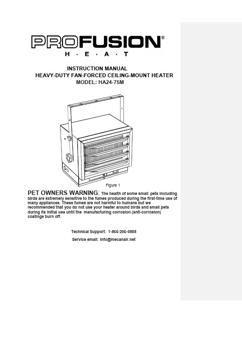
INSTRUCTION MANUALHEAVY-DUTY FAN-FORCED CEILING-MOUNT HEATERMODEL: HA24-75MPET OWNERS WARNING : The health of some small pets includingbirds are extremely sensitive to the fumes produced during the first-time use of many appliances. These fumes are not harmful to humans but werecommended that you do not use your heater around birds and small pets during its initial use until the manufacturing corrosion (anti-corrosion) coatings burn off.Technical Support: 1-866-206-0888 Serviceemail:*****************Figure 1TABLE OF CONTENTS Important Instructions (3)Description and Specifications (4)General Safety Information (5)Locating heater (6)Installation........................................................7-9 Co nnecting the power........................................9-12 Operating Instructions.......................................13-14 Maintenance Instructions (14)IMPORTANT INSTRUCTIONSWhen using electrical appliances, basic precautions should always be followed to reduce the risk of fire, electric shock, and injury to persons, including the following:1. Read all instructions before installing or using this heater.2. This heater is hot when in use. To avoid burns, do not let bare skin touch hot surfaces.Keep combustible materials, such as furniture, pillows, bedding, papers, clothes andcurtains at least 3 feet (0.9 m) from the front of the heater and keep them away from the sides and rear.3. Extreme caution is necessary when any heater is used by or near children or invalids andwhenever the heater is left operating and unattended.4. Always turn off the power of heater when not in use.5. Do not operate any heater after it malfunctions, had been dropped or damaged in anymanner. Disconnect power at service panel and have heater inspected by a reputableelectrician before reusing.6. Do not use outdoors.7. This heater is not intended for use in bathrooms, laundry areas and similar indoorlocations. Never locate heater where it may fall into a bathtub or other water container.8. To disconnect heater, turn controls to off, and turn off power to heater circuit at maindisconnect panel.9. Do not insert or allow any foreign objects to enter any ventilation or exhaust opening asthis may cause an electric shock or fire, or damage the heater.10. To prevent a possible fire, do not block air intakes or exhaust in any manner. Do not useon soft surfaces, like a bed, where openings may be blocked.11. A heater has hot and arcing or sparking parts inside. Do not use it in areas wheregasoline, paint, or flammable liquids are used or stored.12. All wiring must be carried out by a certified electrician and comply with national and localelectrical codes in the United States and Canada.13. Use this heater only as described in this manual. Any other use not recommended by themanufacturer may cause fire, electric shock, or personal injury.14. This heater may include a visual alarm to warn that parts of the heater are gettingexcessively hot. If the alarm turns on, immediately turn the heater off and inspect for any objects on or adjacent to the heater that may have blocked the airflow or otherwisecause high temperatures. DO NOT OPERATE THE HEATER WITH THE ALARMILLUMINATING.SAVE THESE INSTRUCTIONS2DESCRIPTIONThe heavy-duty electric heater is designed for garages, workshops and similar locations. It features two heat settings, for a maximum heat production of 25,589 BTU per hour. It includes horizontal and vertical air flow and a built-in thermostat with overheating safety thermal cut out.SPECIFICATIONSCircuit diagram Figure 2Warning: This appliance must be grounded!Warning: The appliance must be connected to a 45-Amp current protection circuit or device before being connected to power supply!3GENERAL SAFETY INFORMATION: This heater requires a hardwire installation (no plug). The installation ofthis product must be carried out by a certified electrician and in accordance with all local and national electrical codes.NOTE: This appliance is compatible with a 240V line voltage single pole wall thermostat(not included). This heater must be installed by a certified electrician.Read and understand all installation and operation instructions prior tooperating this unit. Observe all safety instructions at all times. 1. Use only copper wires rated for at least 60ºC.2. Heater air flow must be directed parallel to or away from adjacent wall.3. Observe wall, floor and ceiling clearance requirements.4. All wiring must be done according to national and local electrical codes in the United States and Canada. The heater must be grounded as a precaution against possible electrical shock. Heater circuit must be protected with proper fuses.5. The mounting structure and the anchoring hardware must be capable of supporting the weight of the heater and the mounting bracket (if used).6. All electrical power must be disconnected and the main service box, which must be locked before connecting, inspecting, cleaning or servicing the heater. This is a precaution to prevent serious electric shock.7. This heater is not suitable for use in hazardous locations as defined by the national fire protection association (NFPA) in the United States. This heater has hot and arcing sparking parts inside. Do not use it in areas where gasoline paint or flammable liquids are used or stored.8. This heater is not suitable for use in corrosive atmospheres such as marine greenhouses or chemical storage areas.9. This heater must be mounted at least 8 feet above the floor.Improper installation or failure to follow the procedures outlined in thisinstruction manual can result in serious electrical shock.LOCATING HEATERInstall heater out of traffic areas, maintaining clearances stated in figure 3. The direction of air flow should not be restricted by columns or machinery and the air flow should wipe exposed walls rather than blowing directly on them. When more than one heater is used in an area, the heaters should be installed in a way that the air discharge of each heater supports the air flow of the others, to provide best circulation of warm air as indicated in figure 4.14in.36 in.73 8in.1MINIMUM DISTANCE FROMDISCHARGE TO ANY OBJECTNote: M in. clearance t o ceiling when not using mounting bracketsin.DISTANCE TO FLOOR8 ft.is 158 in.FRONT VIEWMAXIMUM MOUNTING HEIGHT:Vertical air delivery unit = 11 ft.SIDE VIEWFigure 4Figure 33’’3 ’’ INSTALLATIONHardware neededstore or electrical supply store:● ● Proper size fuse or breaker ● ●Mounting the BracketRefer to Figures 5a and 5b.1. screw them securely into a ceiling joist.secure the unit. See Figure 5a.WASHERWASHERBRACKET8 DIAGONAL LAGBOLTFigure 5a-single-Screw Mounting 8DIAGONAL LAG BOLTFigure 5b-Double-Screw M ountingHANGING THE HEATER1) Lift the heater up and into the mounting bracket.2) Align the bracket screws with the keyhole slots in the mounting bracket.3) If the heater is to be tilted, it must be positioned in the keyhole slots - see figure 6. 4) Tighten the bracket screws with a wrench to secure the unit once suspendedat horizontal or vertical level.KeyholesUSE BOTTOM KEYHOLE SLOTS IF HEATER IS TO BE TILTED DOWNBracket S crewsFigure 6REMOVE S CREW T O OPEN COVERADJUSTING AIR FLOW DIRECTION1. To turn the unit when it has been installed with a single lag bolt (as shown in figure 5a), simply turn the entire heater as needed. The unit cannot be turned horizontally if it has been installed with 2 lag bolts.2. To tilt the unit vertically, loosen the bracket screws (see figure 6).3. Adjust louvers to the desired position.NOTE: The louvers are designed so they cannot be completely closed. Do not attempt to defeat this feature; damage to the unit can result. NOTE: To prevent possible overheating, please maintain adequate clearance as shown in figure 3.Figure 7MULTIPLE VERTICAL ANGLESFigure 8MOUNTING THE HEATER IN THE WALL ’S WOOD STUDSRefer to Figures 9A to 9E .(Figure 9A)2. Install the tripod on the wall with two screws. (Figure 9B)5. Adjust the horizontal angle (Figure 9E)Attach with screw (M4*12*1)Support plate2. Install the bracket on the wall with two screws (ST10*30*2)Tripod1. Slide the support plate into the tripodFigure 9A Figure 9B3. Use the keyholes to lock different anglesFigure 9CFigure 9B(M10*20*1)Figure 9D5. The heater can be tilted at 3 different angles. Use two screws (M6*16*2) tosecure the unit in each angle.45° TOP VIEW45°Figure 9ENOTE: The louvers are designed so they cannot be completely closed. Do not attempt todefeat this feature; damage to the unit can result.CONNECTING THE POWERExternal thermostat wiring diagramFigure 9NOTE: If you use an external temperature control (external thermostat),please follow the instructions below:Note 1: You must turn off the ON/OFF switch on the front of heater before you select the built-in / external thermostat.Note2. Please find the rocker switch on the back of the heater as s hown in Figure 10 and shift the switch to “—” position. Then the heater will be controlled by external thermostat.Figure 10Note3. Connect the wire according to wiring diagram as sh own in figure 9.Note4. The external temperature control (external thermostat) should comply with UL or ETL standard requirements.Note5. The lead wire of external temperature control (external thermostat) must have a minimum gauge of 16 AWG.External thermostat installation:1. Pop the piece out to open the hole2. Remove both screwsFigure 11A Figure 11B3. Strip away the cover of lead wire for 50mm4. .Twist the wire through the end From the external control box.Figure 11C Figure 11D5. Bend each wire into a circle6. Place the twisted wires through the holeFigure 11E Figure 11F7. Connect the wires to the heater and secure in place.Figure 11G8. Tighten back the screws with a screwdriverFigure 11HConnection of power cables:1. Remove the screw from the front of the unit to connect the power to the heater.2. Attach the cable connectors to the unit (See Figure 12) and slide the 10-gauge wirethrough the cable connector.3. Connect the wire to the power block located in the base of the heater - See Figure 13.4. Turn on the power at the main service panel.NOTE: All wiring must be carried out by a certified electrician and comply with national and local electrical codes in the Canada & United States. For certain applications, conduit may be required. Check local electrical codes. If you run the wiring in conduit and wish to be able to turn the heater be sure to purchase enough flexible conduits to allow the heater to be turned.Figure 12OPERATING INSTRUCTIONSNote: After setting an external thermostat to control the heater, the power selection switch on the unit will be the only working function on the heater itself.WARNING: the heater must be properly installed before it is used.TO PROTECT THE HEATING ELEMENTThe heater includes a fan delay function to prevent overheating.When starting the heater, the unit will start the heating element first and then start the fan when the heating element reaches a certain temperature. When turning the heater off, the unit will turn off the heating element first; the fan will continue to work for a few minutes to dissipate residual heat.SETTING THE THERMOSTAT1) Rotate thermostat knob clockwise to its highest position; the amber POWER INDICATOR will turn on.2) Once the room reaches your desired comfort level, rotate thermostat knob counter-clockwise until a click is heard, then rotate it slightly clockwise.Your heater will now cycle on and off to maintain your set room temperature.POWER SELECTION SWITCHUsing the SELECTION SWITCH, select the heatingoutput: I for 5000W, II for 7500WTHERMOSTATSELECTIONSWITCHTHERMAL CUT-OUTThe heater will automatically turn off when parts of it overheat. When this happens, the red indicator will turn on. The heater will turn ON again and the red indicator will turn off when the unit cools down back to normal levels, but the reason of the overheating must be determined and corrective action taken before further operation.THE HEATER MUST BE TURNED OFF IMMEDIATELY WHEN THE CAUTION INDICATOR IS GLOWING RED.NOTE: When the thermal cut-out is activated, the caution indicator will turn red.In this case, immediately turn the heater OFF and inspect for any objects on or adjacent to the heater that may cause high temperatures. Let heater cool off completely before turning on again.MAINTENANCE INSTRUCTIONS1. Before cleaning, make sure the power has been turned off at the circuit breaker panel andthe heating element of the heater is completely cool.2. To maintain the appearance of the heater, it need only be wiped over occasionally with adry duster. During the summer months, or at other times when the appliance is not in use and is completely cold, it can be cleaned by wiping it with a damp cloth. Do not let water drip inside the heater.3. Do not use abrasive clearing powders or furniture polish to clean this appliance. Do notuse chemical or abrasive products, metallic scourers and similar items; they maydeteriorate the surface.4. During the summer months, or at other times when the appliance is not in use,disconnect the power supply, and cover the whole appliance with a dust cloth.Storethe appliance in a dry and cool place.5. All servicing should be performed by qualified service personnel. Do not try to repair theheater yourself.。
JULABO加热制冷恒温循环器F38-EH中文操作说明书

操作手册加热和制冷循环器F38-EH祝贺!您做出了明智的选择。
JULABO 非常感谢您对我们的信任。
这本操作手册是专门用来帮助您的,它会使你对操作的规程和你选择我们的循环器后的 保障有所了解。
为了给予所有功能最适当的发挥空间,我们建议您在开始操作之前先通 读这一手册。
质量管理体系拆箱和检查拆开循环器和附件的包装,检查在运输途中是否有损坏。
这方面信息要反馈给相关部门(货运,铁路运输等),如果有破损的地方,就请对方出具破损报告,这些信息也请保存好,必要时会得到我们的全力支持。
对于没有预先通知的更改,我们保留有解释权。
目录操作手册 (4)简介 (4)操作人员职责-安全建议 (5)EC统一申明 (7)保修条件 (8)技术参数 (9)操作指南 (11)1.操作控制及功能项 (11)2.给用户的安全指示 (12)3.准备工作 (12)3.1安装 (12)3.2浴液 (13)3.2.1管材 (14)3.3注入/排出 (16)3.4外循环系统的温控应用 (17)3.5可调泵流量 (17)4. 操作步骤 (18)4.1电源连接 (18)4.2电源开关/运行-待机 (18)4.3自动/非自动运行模式 (19)4.4设置温度 (20)4.5过温保护 (20)4.6绝对温度校准 (21)4.7定时功能 (22)4.7.1时间设置 (22)4.7.2定时功能操作 (22)5.发现故障并维修指南/错误信息 (23)6.安全建议 (25)7.电源接头 (26)8.保持制冷能力 (26)9清洗仪器 (27)操作手册简介JULABO循环器是为特定浴槽浴液的温控应用所设计、准备的,我们的仪器提供可做外循环系统温控应用的泵接口(回路)。
操作人员职责-安全建议如果您是按照标准的安全规则来正确进行安装,操作以及维护的,JULABO德国有限公司的产品保证您的操作安全。
这一章节告诉你一些在对循环器进行操作的过程中有可能引起的潜在危险,同时也提示您有关的重要安全防范。
Vaisala HM40系列蜂鸟型号湿度与温度仪的概述与特点说明书

Bid Specification 1 (3) 2019-06-05 © Vaisala 04/l 2014 This material is subject to copyright protection, with all copyrights retained by Vaisala and its individual partners. All rights reserved. Any logos and/or product names are trademarks of Vaisala or its individual partners. All specifications — technical included — are subject to change Vaisala Inc.1-888-VAISALA (824-7252) ***********************HM40 Series Compact and Portable Humidity and Temperature MeterHM40 Overview: ▪ Wide measurement range and displays multiple parameters (RH, T, Td, Tw, a, x, h) ▪ Standard and remote probe models available ▪ Ideal for spot-checking, on the go ▪ Incorporates the proven Vaisala HUMICAP ® 180R Sensor ▪ Graphical display indicates when measurement has stabilized ▪ Convenient calibration – either replace interchangeable probe or calibrate in the field HM41 Features/Benefits ▪ Incorporates the proven Vaisala HUMICAP ® 180R Sensor ▪ Interchangeable HMP113 probe ▪ IP54 Rating ▪ Temperature measurement range of -10 … +60 °C (+14 … +140 °F) ▪ Designed for spot checking in rooms ▪ Probe material: PC/ABS plastic blend HM45 Features/Benefits ▪ Incorporates the proven Vaisala HUMICAP ® 180R Sensor ▪ Interchangeable HMP113 probe with HM40HANDLE▪IP54 Rating ▪ Temperature measurement range of -40 … +60 °C (-40 … +140 °F) ▪ Designed for spot checking in difficult to reach areas ▪ Probe material: PC/ABS plastic blend[Unit] / Tiina Vainio Bid Specification 2 (3)2019-06-05▪Incorporates the proven Vaisala HUMICAP® 180RSensor▪Interchangeable HM46PROBE▪IP54 Rating (indicator), IP40 (probe)▪Temperature measurement range of -40 … +100 °C (-40 … +212 °F), short term up to +180 °C (+356 °F)▪Designed for spot checking in HVAC applications andin ducts▪Probe material: Stainless steel, brass filterHM41 Summary:Relative humidity and temperature portable calibrator shall incorporate a thin film polymer capacitive HUMICAP® humidity sensor and have accuracy of ±1.5% RH (0…90% RH) and ±2.5% RH (90…100% RH) between 0 to 40°C (32 to 104°F). Shall have typical long-term stability of better than ±2% RHover 2 years. Temperature sensor shall be a platinum 1000Ω RTD with accuracy of ± 0.2°C (0.36°F)between °0 … +40 °C (+32 … +104 °F) with a measurement range of -10 ... +60 °C (14 ... 140 °F). Indicator shall additionally be able to calculate and display dew point, wet bulb temperature, absolute humidity, mixing ratio and enthalpy. The graphical LCD display shall feature multilingual menu-based user interface. NIST traceable calibration certificate included. Shall have the ability to be calibrated by the user in the field or shall offer an interchangeable calibrated probe.HM45 Summary:Relative humidity and temperature portable calibrator shall incorporate a thin film polymer capacitive HUMICAP® humidity sensor and have accuracy of ±1.5% RH (0…90% RH) and ±2.5% RH (90…100% RH) between 0 to 40°C (32 to 104°F). Shall have typical long-term stability of better than ±2% RH over 2 years. Temperature sensor shall be a platinum 1000Ω RTD with accuracy of ± 0.2°C (0.36°F) between °0 … +40 °C (+32 … +104 °F) with a measurement range of -40 ... +60 °C (-40 ... 140 °F). Indicator shall additionally be able to calculate and display dew point, wet bulb temperature, absolute[Unit] / Tiina Vainio Bid Specification 3 (3)2019-06-05humidity, mixing ratio and enthalpy. The graphical LCD display shall feature multilingual menu-based user interface. NIST traceable calibration certificate included. Shall have the ability to be calibrated by the user in the field or shall offer an interchangeable calibrated probe.HM46 Summary:Relative humidity and temperature portable calibrator shall incorporate a thin film polymer capacitive HUMICAP® humidity sensor and have accuracy of ±1.5% RH (0…90% RH) and ±2.5% RH (90…100% RH) between 0 to 40°C (32 to 104°F). Shall have typical long-term stability of better than ±2% RH over 2 years. Temperature sensor shall be a platinum 1000Ω RTD with accuracy of ± 0.2°C (0.36°F) between °0 … +40 °C (+32 … +104 °F) with a measurement range of -40 ... +100 °C (-40 ... 212 °F). The probe shall be capable of withstanding a temperature of up to +180°C (356°F) for a short period of time. Indicator shall additionally be able to calculate and display dew point, wet bulb temperature, absolute humidity, mixing ratio and enthalpy. The graphical LCD display shall feature multilingual menu-based user interface. NIST traceable calibration certificate included. Shall have the ability to be calibrated by the user in the field or shall offer an interchangeable calibrated probe.。
绝对高大上Nest温控器国内应用指南
绝对高大上!Nest温控器国内应用指南自从NEST被Google以32亿美元收购后,整个智能家居行业都很振奋,有关NEST 的新闻铺天盖地,一下子NEST的智能恒温器Thermostat和烟雾探测器Protect 被大家所熟知,笔者作为智能家居的行业内人士很早就知道这款智能恒温器产品,并且想把这款产品引进的国内使用,但是详细了解了NEST的这款温控器后,发现这款产品是针对美国的家庭空调系统使用的(美国的空调系统使用的24V控制电压),所以在国内使用有很大的困难,包括空调系统都跟国内不一样。
即使是NEST的英国官网也仅推出了智能烟感器,也没有推出温控器,想必也是因为空调系统的控制方式不一样导致的。
相信NEST在被Google收购后肯定要做全球的市场推广,针对不同国家的HVAC系统肯定会有不同的产品推出,那么在这之前我们能抢先体验使用这款智能的家居产品吗?在笔者深入研究了解后,答案是肯定的,针对国内的空调系统我们只需做一些技术上的改动便可以使用这款温控器,那么下面我就做详细介绍。
1、要知道怎么改造之前,先要了解一下NSET Thermostat在美国是如何应用的,那么就要先了解一下美国的家庭的制冷制热空调系统(HVAC系统)。
在美国大部分家庭都是这样的独栋房屋,有一套独立的空调及锅炉系统用来制冷或制热。
如图中所示,室外放的热泵系统主机(可以制冷或制热),室内放的空气处理系统主机(包含新风系统)有些寒冷地区会采用燃气锅炉,然后采用风管式空调系统将冷风或热风吹到各个房间,在一层的房间里安装了一个温度控制器,用来控制整个房屋的温度。
NEST的智能温控器就是用来替换这个传统温控器的。
由此可见,美国的家庭一般只需要一个温控器就可以控制全宅的空调系统。
对空调系统比较了解的朋友就应该知道美国的这套空调系统跟国内的有所不一样,国内一般别墅住宅多采用冷热水机组空调或VRV系统空调。
VRV空调系统这种空调系统通常在每个房间独立控制本房间的温度,所以在每个房间都有一块空调的控制面板,如果还安装了地暖系统,那么还有一块地暖的控制面板。
美国Chromalox科模热思加热器

美国Chromalox科模热思加热器美国Chromalox(科模热思)Chromalox,总部设在匹斯堡,电加热器电伴热带,传感器,温度控制器美国CHROMALOX电热组件,浸⼊式电热器,循环式电热器,幅射式电热器,电热锅炉及热交换系统,空调温度加热器,热风机,单回路及多回路温度控制器及控制系统90多年来,Chromalox ⼀直致⼒于为客户提供最⾼品质的创新型商业及⼯业⽤加热应⽤解决⽅案。
该公司拥有全球规模最⼤、范围最⼴的电热及控制产品线,其中包括加热部件、浸没式加热器、循环系统、热传系统、锅炉、⼯业⽤舒适性空⽓加热系统、热追踪电缆、传感器和精密电⼦控制器。
Chromalox 总部位于美国宾⼣法尼亚州匹兹堡,在北美、欧洲和亚洲设有多个⽣产、设计、仓储和销售中⼼,是提供最⾼⽔平的客户⽀持的全球性供应商。
Chromalox 拥有业界最⼴泛的产品线,其加热及控制解决⽅案的应⽤范围堪称世界之最。
Chromalox伴热带简介:⼀、⾃调控SRM/E ⾃调控中温电伴热带(14AWG)、⾃调控,⾼效节能、美标14 AWG铜母线、单根回路最长达238⽶(780英尺)、最⾼维持过程温度为:150°C(302°F)SRL系列⾃调控低温电伴热带⾃调控,⾼效节能、美标16 AWG铜母线、单根回路最长达201⽶(660英尺)、最⾼维持温度为65°C(150°F)、更多产品信息请查阅产品⽬录PDF⽂件SRP⾃调控⼯艺温度电伴热带⾃调控,⾼效节能、美标16 AWG同母线、单根回路最长达228⽶、最⾼维持温度为107°C(225°F)、更多产品信息请查阅产品⽬录PDF⽂件SRS⾃调控中温电伴热带(20AWG)⾃调控,⾼效节能、美标20 AWG铜母线、单根回路最长达110⽶(360英尺)、最⾼维持温度为150°C(302°F)、更多产品信息请查阅产品⽬录PDF⽂件代理采购德国、美国进⼝⼯业品,进⼝仪器仪表,进⼝备品备件,欢迎咨询秦皇岛维克托国际贸易有限公司联系⼈:张⼩姐⼿机:186********电话:0335-*******-817 传真:0335-*******QQ:1642479859 E-Mail:1642479859@⼆、恒功率CWM并联恒功率电伴热带、回路长度:最⼤238m、最⼤过程维持温度:176摄⽒度、功率:13、26、39W/m、电压:120V、208-277V 、480V。
电热恒温培育箱使用步骤说明及操作规程

电热恒温培育箱使用步骤说明及操作规程电热恒温培育箱使用步骤说明电热恒温培育箱是适用于医疗卫生、医药工业、生物化学和农业科学等科研和工业生产部门做细菌培育、发酵及恒温试验用的一种恒温培育箱,正确的使用步骤能够是测量或是寿命达到更好的效果,一起来看下:1.电热恒温培育箱操作规程1.1把电源开关拨至“l”处,此时电源指示灯亮,控温仪上有数字显示;1.2温度设定a.当所需加熟温度与设定温度相同时不无原则设定,反之则需重新设定。
先按控温仪的功能键“SET”进入温度设定状态,SV设定显示一闪一闪,再按移位键“◢”搭配加键“△”或减键“”设定结束需按功能键“SET”确认。
b.如无需设定37~C,原设定26.5~C,先按功能键“SET”,再按移位键“◢”,将光标移至显示器十位数字上,然后按加“△”,使十位数字从“2”升至为“3”,十位数设定后,移动光标依次设定个位和分位数字,使设定温度显示为37~C,按功能键“SET”确认,温度设定结束。
1.3上限跟踪报警设定产品出厂前已设定高10C,一般不要进行设定。
如需重新设定按功能键“SET”5秒,仪表进入上限跟踪报警设定状态“ALl”再按移位键“◢”搭配加键“△”或减键“▽”操作,最后按功能键“SET”确认。
跟踪报警设定结束。
1.4温度显示值修正由于产品出厂前都经过严格地测试,一般不要进行修正。
如产品使用时的环境不佳,外界温度过低或过高,会引起温度显示值与箱内实际温度误差,如超出技术指标范围的,可以修正。
实在步骤:按功能键“SET”5秒,仪表进入参数设定循环状态“ALl”,连续按动功能键“SET”,使”显示“SC”修正,然后按动移位键“”搭配加键“△”或减键“▽”操作,就可以进行温度修正。
最后按键“SET”确认,温度显示值修正结束。
1.5设定结束后,各项数据长期保存。
此时培育箱进入升温状态,加热指示灯亮。
当箱内温度接近设定温度时,加热指示灯亮忽亮忽熄,反复多次,掌控进入恒温状态。
- 1、下载文档前请自行甄别文档内容的完整性,平台不提供额外的编辑、内容补充、找答案等附加服务。
- 2、"仅部分预览"的文档,不可在线预览部分如存在完整性等问题,可反馈申请退款(可完整预览的文档不适用该条件!)。
- 3、如文档侵犯您的权益,请联系客服反馈,我们会尽快为您处理(人工客服工作时间:9:00-18:30)。
5 注意事项
1) 取样群和跟随群的群势应大致相同, 各蜂群 的保温情形、巢门大小、受光照射、受风吹的情形也 应尽可能一致。
图 4b 为 双 向 可 控 硅 BCR6AM( 正 面 朝 上 ) 的 引 脚排列图, 接线时切勿搞错。 1.6 调试
将 电 热 ( 毯 ) 线 RL 编 织 在 2 块 平 式 隔 王 板 上 , 构成 2 个标准发热块, 并将它们叠放在一起, 盖上保 温物; 把探头 W 塞入二标准发热块之间, 接通电源。 当外界气温低于 24.5 ℃时, 指示灯亮, 说明 RL 已通 电加热, 发热块之间的温度逐渐升高; 当温度达 24.5 ℃时, 指示灯 ZD 熄灭, 表明: 电路被切断, RL 停止加热。
当 W 所 处 位 置 的 温 度 升 高 到 24.5 ℃时 , f 向 右 移至 D 点, 使 B,D 两点导通, 将 4.3 mA 的 触 发 电 流 短 路 , K 失 去 触 发 电 流 而 截 止 , 关 断 了 RL 的 电 流 , 停止加热。
如此周而复始, 使箱内 ( 蜂团周围) 温度始终恒 定 在 24.5 ℃附 近 , 从 而 达 到 了 对 蜂 群 实 施 恒 温 加 热 之目的。
将 10 条电热 ( 毯) 线分别编织在 20 块平式隔王 板上, 构成 20 个 标 准 发 热 块 , 每 个 发 热 块 加 热 1 群 蜂。
按图 5b 所示, 把 10 条电 热 线 RL1~RL10 并 联 起
25
蜜蜂杂志 (月刊)
J OURNAL OF BEE ( Monthly)
NO.1 2007 Jan.
来接在 CT 上, 插入 CZ 内。 接通 ( AC 220 V) 电源即可。
4 管理
1) 开 始 加 热 的 头 3 天 , 每 天 分 别 于 早 上 8:00, 下 午 3:00 用 酒 精 温 度 计 ( 从 巢 门 插 入 ) 各 测 一 次 巢 温, 各群巢温的差异应≤±2 ℃, 若超过该范围, 则 做相应调整: 温度过高的群应开大巢门, 减少保温 物, 加强通风, 减少光照。调整正常后, 每 3 天测温 1 次。
①所需功率: 每个被加热群消耗 25 W 功 率 , 则 22 群所需总功率为 550 W< 2.5 kW ( 从 DZ 输出的功 率) 。可行。
② 电 热 ( 毯 ) 线 条 数 n: 每 2 群 需 ( 220 V 50 W) 电热 ( 毯) 线 1 条, 则 22 群蜂需 11 条, 除去恒 温控制器自带的 1 条 ( RL) 外, 还需要电热 ( 毯) 线 条数 n=10。 2) 实施
1 第二代恒温加热器
1.1 组成 如 图 1 所 示 , 电 路 由 温 度 检 测 探 头 W、 触 发 电
阻 R、双向可控硅 K 和加热器 RL 共同组成。 RL
220V 50W
AC220V
R
51kΩ 2W B DF
K BCR6AM
图 1 第二代恒温加热器电路图 其 中 RL 是 一 根 220 V 50 W、 长 10 m 的 电 热 ( 毯) 线, 把它均匀地编织在 2 块平式隔王板的竹栅 内, 每块布线 14 行, 用线 5 m, 功 率 25 W, 每 块 各 加 热 1 群 蜂 。 详 细 制 作 方 法 参 阅《 蜜 蜂 杂 志 》2006 年第 11 期 19 页问 12) 。 我们把这种编织在 1 块平式隔王板上的 ( 25 W) 发热块, 叫做标准发热块。 1.2 各元器件的作用 双向可控硅 K 负责“ 接通”和“ 关断”供 给 RL 的 电流; 触发电阻 R 的作用是向 K 提供一个触发电流, 使 K 导通; 而控制加热电流通、断的讯号则由探头 W 提供; 对蜂群加热的任务最终由 RL 完成。 1.3 原理 温 控 器 的 探 头 W ( 控 温 温 度 设 定 在 24.5 ℃) 挂 在被加热蜂群的第一隔板外侧 ( 如图 2 所示) 。
5. 箱盖 6. 巢脾
7. 第一隔板 8. 探头
9. 第二隔板
10. 保温物
收稿日期: 2006- 11- 22
a. 用 TH108 改制的探头 b. 探头的符号 图 3 探头的制作
1.5 组装 恒温加热器的 R 和 K 两个元件安装在 1 只
3CT5- 1型电热毯开关盒内。 连 接 探 头 及 电 热 ( 毯 ) 线 RL 的 导 线 分 别 从 盒 的
BX1
BX2 5A
5A R 51K
CZ CT
2W
AC 220V
T2
K
T1 BCR 25AM B
DF
R L1 R L2
R Ln
50W 50W
50W
W a. R L 加热两个取样群
图5
b. R L1 ̄R Ln 用 于 加 热 2n 个 跟 随 群 第三代恒温加热器
从 CZ 可输出 2.5 kW 供给其余的 n 条 ( 220 V 50 W) 电热 ( 毯) 线 ( LR1~LRn) , 对另外的 2n 个 ( 标 准箱) 群进行加热。我们把这 2n 个蜂群叫做跟随群, 即取样群被通电加热, 跟随群亦被加热; 取样群停止 加热, 跟随群也停止加热。
这两条导线可合用一根 1 m 长的电话机用 ( 软) 双芯连接线。
这样, 在 B,D 间就 构 成 了 一 个“ 温 度 检 测 开 关 ”, 简称探头。其符号如图 3b 所示。
- 20
FD
B ℃
50
F BD
W
1
6
7
9 10
8
2 3
4
图 2 被加热蜂群示意图
1. 继箱 2. 塑料纱底 3. 电热毯 4. 活动箱底
将待加热的蜂群提入箱内, 巢脾按从左到右的秩 序排列好; 插下第一块隔板, 在该隔板中部钉 1 枚小 钉子, 把探头 W 挂在钉子上。此群为取样群。在 W 外侧插第二块隔板, 在该板外加保温物。
另外一群为非取样群, 仅用 1 块隔板。两群并列。 接通电源即可实现对蜂群实施恒温加热 ( 参阅图 2) 。
1 直式隧道巢门可防治盗蜂
在外界蜜源较少或晚秋等盗蜂活动猖狂的季节, 使用直隧道巢门可有效预防和制止盗蜂。具体做法 是: 首先准备好 2 根圆木棍, 一根粗一根细, 细木棍 直径在 1 cm 左右, 粗木棍直径在 2 cm 左右, 木棍长 15 cm 左右; 和好一部分稀泥, 泥不要太稀, 以能捏 成团为度; 把小木棍一头伸向巢门口, 在巢门口小木 棍 周 围 糊 上 泥 , 要 糊 严 巢 门 , 把 小 木 棍 糊 去 3 cm 长 即可; 糊好泥后, 转动小木棍, 一边转一边抽出小木棍。
以每条电热 ( 毯) 线 50 W, 每群蜂消耗 25 W 功 率 计 算 , 2.5 kW 的 输 出 功 率 可 带 动 电 热 ( 毯 ) 线 的 条 数 n=50; 每 条 电 热 ( 毯 ) 线 可 加 热 2 群 蜂 , 则 可 对 2n=100 群蜂进行加热。
3 应用举例
某 蜂 场 计 划 用 第 三 代 恒 温 加 热 器 对 该 场 的 22 群 蜂实施加热 ( 参阅图 5) , 应先论证其可行性, 而后 组织实施。 1) 计算
进线孔和出线孔引出。如图 4 所示。
2007年第 1 期
蜜蜂杂志 (月刊)
J OURNAL OF BEE ( Monthly)
24
AC220V
R K
F
BD
R1 ZD RL
T1 T2 G
W
a. 各元件连接图
b. 可控硅 BCR 6AM 引脚 ( 正面向上)
图 4 恒温加热器组装图
步 骤 : 拆 开 3CTK5- 1 开 关 外 壳 , 拆 去 盒 盖 上 的 开关手柄、弹簧、触片等物, 留下空盒待用。取出盒 内的线路板 α ( 如图 4a 虚线框内所示) , 从板 α 上 拆除换挡二极管, 保留 ( 氖) 指示灯 ZD 及串在氖灯 上的电阻 R1。将所有元器件焊接在板 α 上。其中电 阻 R 及双向可控硅 K 分别焊在 α 板的正、反面上, 并将该二元件随板 α 装入空盒内; 探头 W 及电热 ( 毯) 线 RL 分别用双芯导线引出盒外。组装工作即告 结束。
1.4 探头的制作 探头 W 由 1 只 TH108 型温湿度计改 制 而 成 , 其
中的温度计是一只由双金属片驱动的指针型温度计, 其表盘如图 3a 所示。
改制方法: 小心撬开 TH108 的外壳, 取出表盘, 在 其 温 度 刻 度 线 上 的 24.5 ℃处 打 一 个 φ2 mm 的 孔 , 在孔内旋 1 枚 φ2 mm 的 ( 镀银) 铜螺丝钉, 在 ( 反 面) 螺丝钉下压 1 块小 ( 铜) 焊片, 在小焊片上焊 1 条软导线引出盒外; 表针置于 D 左侧, 在金属表针 f 与 D 接 触 处 , 用 牛 角 刀 刮 去 f 表 面 的 油 漆 层 , 使 f,D 之间的触点有良好的导电性能。再从转动轴处双金属 片末端的 B 点引出另一条软导线。
2) 各群的加热功率必须严格保持一致, 即 25 W。 3) 由于恒温加热器要不间断地 连 续 工 作 45~60 天, 故对各元器件, 特别是双向可控硅的要求很高, 必须选用正品 ( 或进口) 的元件。 4) 被加热蜂群所消耗的功率之和, 不得大于温 控器的输出功率。 5) 从事对蜂群实施恒温加热的蜂场, 在电路总 闸处必须安装漏电保护器。一旦发生触电事故, 保护 器会自动跳闸切断电源, 从而提高安全性能。 6) 其他未尽事宜, 请参阅《 蜜蜂杂志》2005 年 第 2 期第 5 页 、 第 8 期 第 19 页 和 2006 年 第 11 期 第 18 页的相关文章。
!!!!!!!!!!!!!!!!!!!!!!!!!!!!!!!!!!!!!!!!!!!!!!!!