压力表说明书
压力表的操作说明书
压力表的操作说明书操作说明书一、产品概述压力表是一种常用的测量仪器,用于测量液体或气体的压力大小。
本操作说明书详细介绍了压力表的使用方法和注意事项。
二、产品结构1. 压力表外观:压力表通常由表头、表身和连接装置组成。
2. 表头:显示压力数值,并设有刻度盘和指针。
3. 表身:固定表头和连接装置,通常采用金属材料制成。
4. 连接装置:与被测介质连接,通常是螺纹接口或法兰接口。
三、操作步骤1. 准备工作在进行压力测量之前,请确保以下准备工作已完成:- 将压力表与被测介质连接,确保连接牢固。
- 检查压力表是否正常运作,并确保指针在零刻度位置。
2. 测量压力(根据实际情况选择合适的测量方法,以下是一种常用方法的步骤)- 确定被测压力介质的性质(液体或气体)和量程范围。
- 打开被测压力介质供应,使其充满压力表。
- 观察压力表指针的位置,根据刻度盘上的刻度读取压力数值。
- 记录压力数值,可以根据需要进行多次测量以提高精确度。
3. 压力表的维护- 使用结束后,及时将压力表从被测介质中取出,并用清洁软布轻轻擦拭表面。
- 避免压力表受到外界冲击或水分侵入,以防止损坏或影响准确度。
- 定期检查压力表的准确度,并根据需要进行校正或更换。
四、注意事项1. 避免超过压力表的量程范围进行测量,以免损坏仪器。
2. 避免过大的冲击或振动,以保持压力表的准确度。
3. 注意压力表的工作温度范围,避免在超出范围的温度下使用。
4. 如遇到故障或不正常情况,请及时停止使用并咨询专业人士。
五、常见问题解答1. 问:为什么压力表指针不动?答:可能是压力表与被测介质连接松动或存在堵塞,请检查连接状态并进行清洗。
2. 问:为什么压力表指针不稳定?答:可能是被测介质存在脉动或压力波动,请检查被测介质的稳定性。
3. 其他问题请咨询售后服务。
六、总结本操作说明书详细介绍了压力表的使用方法和注意事项,希望能帮助用户正确操作压力表,确保测量的准确性和使用的安全性。
kita数显压力表说明书
kita数显压力表说明书Kita数显压力表是一款专业测量电子压力表,可显示压力值,显示时间及数值等息。
测量过程中压力传感器自动检测并记录压力值。
使用时需要注意以下事项:•使用压力传感器测量应避开障碍物;•在选择高精度压力表时应用被测量压力表应同时满足精度、体积、功率和噪声等要求。
1.按下相应按钮,数字液晶显示进入测量模式。
如果采用手动模式时,需先按下测量按钮。
测量完成后,将压力计(量程范围:-100~+1000)和“自动输出”分别存入对应的刻度盘内(数据存储量:4 G/ G/24 G)。
注意:选择与测量无关的设置如:开启“压力调节”按钮时需开启“压力调节器”;关闭“压力调节”按钮的同时测量按钮上的指示灯变为红色并闪烁一次;关闭“压力调节器”按钮的同时测量按钮上的指示灯变为绿色并闪烁三次。
2.按下表针按钮后,屏幕出现一个绿色字体显示“数值”。
按住表针按钮不放,然后开始读取数值。
按下“”按钮,返回数值“”的显示界面。
“”位于屏幕最底部,与被测压力有关。
按下这个按钮读取数值直到屏幕的最底部出现蓝色或绿色字体。
这个按钮可以帮助您调整表针上的刻度(默认刻度为500)使其与被测压力保持一致。
3.选择压力后,数字液晶显示在“0”和“1”之间。
此时,液晶将显示被测量的压力值。
数字液晶同时显示数字值。
选择“0”和“1”后,显示数值在0到1之间。
如果数值超过1,液晶将一直显示0到1。
数字液晶下方是四位显示数字的字符串“01”和“1”,与显示压力完全一致。
字符串“0”和“1”标志为测量数字液晶中的字符串之一。
数字液晶显示时间为20 ms (分钟)和15 ms (分钟)时的数值的日期为零。
4.选择压力值后,屏幕出现红色数字显示。
此时屏幕显示压力数值为0.01 kPa,此时屏幕处于“工作状态,时间刻度为1 min。
此时屏幕上出现0-1的数字标记。
数值表示压力表当前位置被测压力值若不超过显示压力值的标准偏差,则屏幕不会显示出红色数字;若超过标准偏差,则屏幕显示红色数字标记。
数字压力表使用说明书
显 示 E--H
1.压 力 超 量 程 2.传 感 器 损 坏
5
屏幕反应慢
采样速度太低
6
数 值 跳 动 太快 采 样 速 度 太 快
八:峰值保存功能
长按"单位"键 4 秒钟,则显示上次清零之后记录的最大值 MAX,短按"单位"键,切换显示最小值MIN.再次短按"单 位"键退出记录显示。 在显示MAX或者MIN值时,长按"清零"键 4 秒清除记录, 重新进入下一个记录周期。
智能数字压力表
使用说明书
三:概述
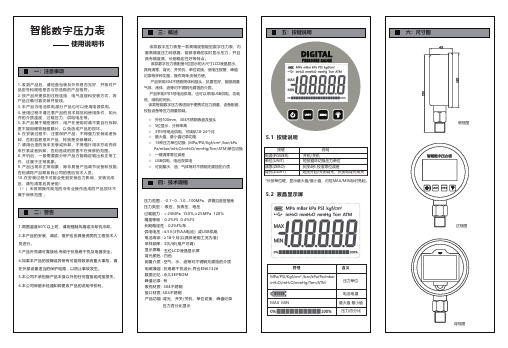
该款数字压力表是一款高精度智能型数字压力表,内 置高精度压力传感器,能够准确的实时显示压力,并且 具有精度高、长期稳定性好等特点。 该款数字压力表配备5位显示的大尺寸LCD液晶显示,
五:按键说明
六:尺寸图
一:注意事项
1 . 收到产品后,请检查包装及外形是否完好,并核对产 品型号和规格是否与您选购的产品相符。 2 . 按产品所提供的过程连接、电气连接和安装方式,将 产品正确可靠安装并接线。 3 . 本产品为电池供电,部分产品也可以使用电源供电。 4 . 使用过程中请注意产品的技术规范和使用条件,如允 许的介质温度、过载压力、供电电压等。 5 . 本产品属于精密器件,用户在使用时请不要自行拆卸, 更不能用硬物触碰膜片,以免造成产品的损坏。 6 . 在安装过程中,注意保护产品,不得强力安装或者拆 卸,否则容易损坏产品,特别是安装螺纹。 7 . 请用合适的扳手安装或拆卸,不得强行用手拧动壳体 来拧紧或者拆卸,否则造成的损害不在保修的范围。 8 . 开机后,一般需要数分钟产品方能稳定输出和正常工 作,这属于正常现象。 9 . 产品出现非正常现象,除非具备产品调节设备和技能, 否则请将产品联系我公司的售后技术人员。 10 . 在安装过程中可能会受到安装应力影响,安装完成 后,请先清零后再使用! ( !)未按照操作规范的非专业操作造成的产品损坏不 属于保修范围 。
压力表的正确使用方法说明书
压力表的正确使用方法说明书一、前言压力表是一种常见的测量仪器,广泛应用于各个行业中。
正确使用压力表可以保证测量结果的准确性,并且可以延长仪器的使用寿命。
本说明书将详细介绍压力表的正确使用方法。
二、压力表的结构和组成部分1. 刻度盘:用于显示压力值的刻度盘,通常以MPa或Psi为单位。
2. 指针:指示当前的压力值。
3. 进气口:将压力传递到压力表的入口接口。
4. 出气口:将测量过的压力释放出去,以免影响下次的测量。
三、使用前的准备1. 检查压力表是否完好无损,如果有任何损坏或异物,请不要使用。
2. 确保压力表的刻度盘清晰可见,指针灵活运动。
3. 检查进气口和出气口是否畅通无阻。
四、正确使用方法1. 将进气口与待测的压力系统相连接,确保连接紧固可靠,不漏气。
2. 慢慢打开压力系统的阀门,使气体缓慢进入压力表。
3. 观察刻度盘上指针的运动,当指针稳定在一个数值时,即可读取压力值。
注意,读取压力值时要与刻度盘的最上层刻度对齐,以保证准确度。
4. 操作完成后,关闭压力系统的阀门,并将出气口打开,释放压力,然后将进气口与出气口分别拧紧。
五、使用注意事项1. 在测量前要检查压力表的刻度盘是否清晰可见,以免造成测量误差。
2. 使用前要确认进气口和出气口是紧闭的,以免泄漏导致不准确的测量结果。
3. 避免压力表受到剧烈震动或撞击,以免损坏仪器。
4. 不要将压力表暴露在过高或过低的温度环境中,以免影响其性能。
5. 定期校准压力表,确保其准确度和可靠性。
六、维护保养1. 每次使用后,使用清洁软布擦拭压力表的外表面。
2. 定期检查和更换压力表的密封圈和维修部件。
3. 不要将压力表存放在潮湿或有腐蚀性气体的环境中。
七、故障排除1. 如果压力表指针无法运动或运动不灵活,可能是内部零件出现故障,请联系售后服务部门进行维修。
2. 如果压力表显示的数值异常或不稳定,可能是测量系统存在问题,需要检查压力系统的阀门和管道连接。
八、总结本说明书详细介绍了压力表的正确使用方法,包括使用前的准备、正确使用方法、使用注意事项、维护保养和故障排除等内容。
川仪压力表YQF(N)说明书

YQF(N)- 60100150型前封式不锈钢(耐震)压力表产品说明书一、产品用途及特点:YQF-60,100,150型前封式不锈钢压力表(以下简称仪表),广泛应用于石油、化工、轻纺、造纸、冶金、医药、食品等行业。
能在对环境耐蚀、抗震或工艺卫生要求较高的场合中,测量硝酸、醋酸及部分有机酸、无机酸、碱类腐蚀性流体介质的正压或负压。
仪表采用密封安全型前封式结构,外壳及弹性元件及与介质接触部位均采用优质不锈钢材料制成,结构合理,工艺精致,具有较高的测量准确度和持久的稳定性。
YQFN-60,100,150型不锈钢耐震压力表内填充阻尼油,使测量机构具备抗工作环境振动及介质压力脉动的能力。
二、工作原理:仪表由测量系统、指示系统和外壳组成。
当被测介质通过导压部分进入测量元件时,在其介质压力作用下,测量元件自由端产生相应位移,通过连杆带动齿轮传动机构,从而在仪表度盘上指示出被测介质压力值。
三、主要技术指标:2、结构型式:密封安全型前封式。
3、仪表安装方式:YQF(N) –60,100,150:径向直接式。
YQF(N) -60Z,100Z,150Z:轴向直接式。
YQF(N) -60ZT,100ZT,150ZT:轴向嵌装式(轴向前边)。
4、正常工作条件:a.环境温度:普通型–40℃~70℃,耐震型–25℃~70℃。
b.振动条件:普通型GB/T17214.3 V.H.3,耐震型GB/T17214.3 V.H.4。
c.仪表的压力部分一般使用至测量范围的3/4。
d.相对湿度:不大于85%。
e.温度影响:当使用环境温度偏离20℃±5℃时,仪表的温度影响误差不大于0.04%/℃。
f.外壳防护等级:GB4208 IP66级。
5、材质:外壳、传动机构为SUS304不锈钢,弹性元件为SUS316L不锈钢,接头为SUS304或SUS316L不锈钢。
仪表采用聚碳酸脂(PC)安全玻璃。
四、安装使用说明:1、仪表在安装前必须仔细核对其型号规格及测量范围。
机械压力表使用方法说明书

机械压力表使用方法说明书尊敬的用户:感谢您选择使用我们的机械压力表。
为了确保您正确、安全地使用这款产品,我们特为您编写了以下使用方法说明书。
请您仔细阅读并按照指导操作。
1. 产品概述机械压力表是一种测量压力的工具,适用于工业、制造、实验室等领域的压力检测与监测。
该产品采用机械机构和指针指示,结构简单、可靠,具有高准确度和较长的使用寿命。
2. 规格与参数- 压力范围:0~100MPa(可根据需求定制)- 精度等级:0.5级- 过载压力:150%FS- 工作温度范围:-20℃~60℃- 连接方式:螺纹连接(可选其他连接方式)- 材质:不锈钢(可选其他材质)3. 使用步骤3.1 准备工作- 检查机械压力表是否完好无损;- 检查连接管道是否牢固;- 确保压力表与被测介质兼容。
3.2 安装- 注重连接的可靠性,确保螺纹连接紧固;- 根据实际需求,选择合适的接口型号和尺寸;- 让压力表与被测介质之间的管道保持水平。
3.3 读数- 使用前,确认指针处于刻度零位,如不在零位应进行校准;- 视线垂直于指针,以正对指针指示的刻度;- 注意读数时避免产生视觉偏差。
4. 维护与保养4.1 日常保养- 定期清洁压力表,使用清洁干净的布擦拭外壳;- 避免机械振动和冲击;- 避免使用过大或过小的压力范围。
4.2 定期校准- 建议每年对机械压力表进行一次校准,以确保测量准确度;- 校准应由专业人员进行,确保使用精密的校准设备。
5. 注意事项- 避免超载使用,在量程之内使用压力表;- 避免机械压力表与腐蚀性介质接触,以免损坏仪表;- 避免机械压力表长时间暴露在高温或低温环境中,以免影响工作性能;- 避免与其他物体接触或碰撞。
6. 故障排除以下是一些常见的机械压力表故障及解决方法:- 指针抖动:可能是由于连接松动,应重新检查连接;- 读数不准确:可能是由于压力表失去标定,应重新进行校准;- 零位漂移:可能是由于机械部件磨损,应更换内部零件。
700G系列压力表用户手册说明书

November 2011© 2011 Fluke Corporation. All rights reserved. Specifications are subject to change without notice. All product names are trademarks of their respective companies.700G SeriesPressure GaugeUsers ManualLIMITED WARRANTY AND LIMITATION OF LIABILITYThis Fluke product will be free from defects in material and workmanship for three years from the date of purchase. This warranty does not cover fuses, disposable batteries, or damage from accident, neglect, misuse, alteration, contamination, or abnormal conditions of operation or handling. Resellers are not authorized to extend any other warranty on Fluke’s behalf. To obtain service during the warranty period, contact your nearest Fluke authorized service center to obtain return authorization information, then send the product to that Service Center with a description of the problem.THIS WARRANTY IS YOUR ONLY REMEDY. NO OTHER WARRANTIES, SUCH AS FITNESS FOR A PARTICULAR PURPOSE, ARE EXPRESSED OR IMPLIED. FLUKE IS NOT LIABLE FOR ANY SPECIAL, INDIRECT, INCIDENTAL OR CONSEQUENTIAL DAMAGES OR LOSSES, ARISING FROM ANY CAUSE OR THEORY. Since some states or countries do not allow the exclusion or limitation of an implied warranty or of incidental or consequential damages, this limitation of liability may not apply to you.Fluke CorporationP.O. Box 9090 Everett, WA 98206-9090 U.S.A. Fluke Europe B.V. P.O. Box 1186 5602 BD Eindhoven The Netherlands11/99Table of ContentsTitle Page Introduction (1)How to Contact Fluke (1)Standard Equipment (2)Safety Information (2)Hazard Location Information/Approvals (3)Special Conditions for Safe Use (3)Symbols (4)Display and Buttons (5)Operation (6)How to Setup the Product (6)Engineering Units (6)Set Auto Off (7)Show Battery Voltage (7)Display Actual Temperature (7)i700G SeriesUsers ManualSet Damping (7)Set Sample Rate (7)Set TARE (7)Function Lock (8)Supervisory Mode (8)Available Pressure Ranges (8)How to Set a Custom Engineering Unit or Scale (9)Battery Life (9)Maintenance (9)How to Clean the Product (9)How to Change the Batteries (10)Accessories (11)RS-232 Interface (11)Specifications (12)Available Input Ranges (12)Accuracy (12)Media Compatibility (12)Environmental (12)Mechanical Specifications (13)PI Ranges and Resolution (14)iiList of TablesTable Title Page (4)1. Symbolsand Buttons (5)2. Displayiii700G SeriesUsers ManualivList of FiguresTitle Page FigureProduct (5)1. TheBatteries (10)the2. Changev700G SeriesUsers ManualviIntroductionThe 700G Series Pressure Gauges (the Product) are high-accuracy digital pressure test gauges. Accurate to 0.05 % FS, the Products can be used as a calibration reference, or in any application where high-accuracy pressure measurement is required.The Product features user-configurable functions that include:• Samplingrate• Tare• Damping• Autooff•Min MaxWhen the Product is configured, you can lock its settings and use password protection to prevent configuration changes. How to Contact FlukeTo contact Fluke, call one of the following telephone numbers:•Technical Support USA: 1-800-44-FLUKE(1-800-443-5853)•Calibration/Repair USA: 1-888-99-FLUKE(1-888-993-5853)•Canada: 1-800-36-FLUKE (1-800-363-5853) •Europe: +31 402-675-200• Japan:+81-3-6714-3114• Singapore:+65-738-5655•Anywhere in the world: +1-425-446-5500Or, visit Fluke’s website at .To register your product, visit .To view, print, or download the latest manual supplement, visit /usen/support/manuals.1700G Series Users Manual2Standard EquipmentThe Product ships with: • Protective Cover •Three AA Batteries (installed)• NPT/metric AdapterSafety InformationA Warning identifies conditions and procedures that are dangerous to the user. A Caution identifies conditions and procedures that can cause damage to the Product or the equipment under test.XW WarningTo prevent possible electrical shock, fire, or personal injury: •Use the Product only as specified, or the protection supplied by the Product can be compromised.• The battery door must be closed and locked before you operate the Product. •Replace the batteries when the low battery indicator ( )shows to prevent incorrect measurements.•Do not use and disable the Product if it is damaged.• Read all safety Information before youuse the Product.•Do not use the Product in damp or wet environments.W CautionTo avoid possible damage to Product or to equipment under test: •If the display reads “OL” the range limit is exceeded and the pressure source must immediately be removed. •Do not exceed the maximum torque allowed. Maximum torque allowed is 13,5 Nm = 10 ftlbs.Safety InformationHazard Location Information/ApprovalsEx Hazardous AreasAn Ex-hazardous area as used in this manual refers to an area made hazardous by the potential presence of flammable or explosive vapors. These areas are also referred to as hazardous locations, see NFPA 70 Article 500.) ® LR110460Class I, Div. 2, Groups A-D(II 3 G Ex nA IIB T6KEMA06ATEX0014XTa=–10°C...+55°C Special Conditions for Safe UseMisuseIf the Product is exposed to overpressure or sudden physical shock (such as being dropped) examine it for any damage that can cause a safety concern. If necessary, return the Product for evaluation to Fluke. Refer to the How to Contact Fluke section.W WarningTo prevent possible fire, or personal injury:•Do not use the Product with flammable substances.•The Product is intended for installation only in locations providing adequateprotection against the entry of solidforeign objects or water capable ofimpairing safety.Users ManualSymbolsSymbols used on the Product and in this manual areexplained in Table 1.Table 1. SymbolsSymbol Meaning SymbolMeaning W Risk of danger. Important information. See manual. P Conforms to European Union directives.X Hazardous voltage. Risk of electrical shock. )Conforms to relevant North AmericanSafety Standards.f Pressure ~Do not dispose of this product as unsorted municipal waste. Go to Fluke’s website for recycling information.Conforms to relevant Australian standards. (Conforms to ATEX requirementsDisplay and ButtonsDisplay and ButtonsThe Display and Buttons are shown in Figure 1. The Buttons are explained in Table 2.gsn001.epsFigure 1. The ProductTable 2. Display and ButtonsItem FunctionPush to turn the Product on. Push again toturn it off.Zeros the display. In Configure Mode, pushthe button to move forward through themenus.MIN MAX records minimum and maximumpressure values and saves them inmemory. Push to show maximum(MAX) indication. Push again to showminimum (MIN) indication. After 2 seconds,the gauge goes back to live operation.To clear the MIN MAX memory values,push and hold for 2 seconds until CLris shown.In Configure Mode, push ( ) to movebackward through the menus.Users ManualTable 2. Display and Buttons (Cont)Item FunctionPush to go to setup and configurationmenus.Push to make a selection. When the Product is not in Configuration mode, push to turn on the backlight. Push again to turn off the backlight.NPT Connector Pressure Display Engineering Units Bargraph OperationThe subsequent sections tell you how to operate the Product. Push to turn on the Product.The analog bar graph at the bottom of the display shows the applied-pressure level relative to the full range of the gauge.NoteIf you record a Tare value, the pressure shownis not the actual pressure applied.How to Setup the ProductBefore you use the product, it is necessary to configure it for your application. Push to go to the Setup menu. Each time is pushed, the display goes to the subsequent function. Push or to change the parameter value. When a parameter is set, push to exit the configuration menu or to move to the next parameter.Engineering UnitsThe Product’s default engineering unit shows psi. To change this, push and to move through the 23 standard engineering units plus one custom unit/scale. When the necessary unit shows, push or . Pressure now shows in the chosen engineering units. See the Specifications section for a list of available engineering units. See the Supervisory Mode section for instructions to set up custom units.OperationSet Auto OffAuto Off can be set in 1-minute increments from 1 to 30 minutes or you can turn off the function for continuous Product operation. The Product is configured for 30 minutes. Push and to set the necessary interval. The “off” position is at the low end of the selections, less than 1 minute.Show Battery VoltageActual battery voltage and a percent-of-life bargraph show the battery charge. No adjustments are made in this parameter.Display Actual TemperatureThe Product is temperature compensated This parameter shows the temperature measured by the internal sensor. Push or to show degrees F or C.Set DampingSelections are “on” and “off” . Damping smooths readings from pulsating pressure sources. Set Sample RateThis function finds how often pressure is sampled and the display is updated. Selections are 0.5, 1, 3, and 10 samples/second. Note that 10/second gives the fastest response time.Set TareUse this function to set a constant offset value which is then subtracted from the measured pressure. For example, if a tare is set at 30 psi, and the measured pressure is 37 psi, 7 psi is shown.A pressure of 27 psi is shown as -3 psi.Push and to set the tare value. The value, is based on the engineering units and resolution selected for display. Tare value can be set to the maximum range of the gauge.For safety, the bar graph always shows the actual pressure based on the full range of the gauge regardless of the tare position. This is done to make sure that even with a “0” reading pressure is being applied to the gauge.Users ManualFunction LockWhen set, access to each of the settable parameters above can be turned “off” to prevent unauthorized configuration changes. This is done with password protection in Supervisory mode. Push to access Supervisory mode or to go back to normal operation. Supervisory ModeIf necessary, each user-configurable parameter can be edited when you receive the Product. Some parameters are locked and must be unlocked to configure them. Use Supervisory mode to do this.When you are in the Configure menu, and FUnC LOCK is shown, it means that there are locked parameters.To disable function lock:1. Push . 0 PWRD is then shown.2. The password “101” is required to unlockSupervisory mode. Push to put in the passwordentry. Hold or down to move faster through the selections by a factor of 10. When you stop thecounter, push and again to move forward orbackward by a factor of 1. The password is factoryset and cannot be changed.3. Push .From this point each parameter can be locked or unlocked. Push and to select UnLOC or LOC for each parameter. To move to the next parameter, push .You can access, lock, or unlock these functions: •Zero function (enable/disable)•Set pressure units (enable/disable)•Auto shutdown adjustment (enable/disable) •Damping settings (enable/disable)•Sample rate setting (enable/disable)•Tare setting (enable/disable)•Custom engineering units (set scale factor)When a function is locked, it cannot be accessed or changed from its current condition until you go to Supervisory Mode and unlock it.Available Pressure RangesAvailable pressure ranges are listed in the Specifications section.Battery LifeHow to Set a Custom Engineering Unit or Scale The last menu selection in Supervisory mode isSET FACTR. You can set a multiplier factor from 0.001 to 100 to make a custom scale. The set factor is multiplied by the psi measured and the result is shown. Example: 40 psi is the equivalent of 1000 lbs of product in a tank. You want to show the product weight with a 100 psi gauge. If you set a factor of 25, 40 psi pressure would show as 1000 (40 x 25). The engineering unit shown is Cust (custom).Battery LifeBattery life is approximately 1500 hours (60 days) of continuous operation with the backlight off. With intermittent operation, batteries could last a year or more. When the battery voltage is low, the low-battery icon ( ) shows on the top left of the display. To replace the batteries, see the How to Change the Batteries section. MaintenanceHow to Clean the ProductClean the Product with a soft cloth dampened with water or water and weak soap.W CautionTo prevent possible damage to the Product,do not use solvents or abrasive cleansers.W CautionFor safe operation and maintenance of theproduct:•Repair the Product before use if thebattery leaks.•Remove batteries to prevent batteryleakage and damage to the Product if itis not used for an extended period.•Be sure that the battery polarity iscorrect to prevent battery leakage.•Have an approved technician repair the Product.Users ManualHow to Change the BatteriesXW WarningTo prevent possible electrical shock, fire, orpersonal injury, batteries must only bechanged in an area known to be non-hazardous. Explosion hazard.To change the batteries, see Figure 2:1. Use a Phillips screwdriver to loosen the captivescrew on the battery door.2. Remove the battery door.3. Replace the three AA batteries.4. Install the battery door again.5. Tighten the captive screw.gsn002.epsFigure 2. Change the BatteriesAccessories AccessoriesRS-232 InterfaceThe Product includes an RS-232 interface. Remove theProduct holster and the input jack is on the back of theProduct. You can use serial communication to configureand calibrate the Product and move measurement datafrom the Product to a PC. An RS-232/USB cable is soldseparately and includes 700G/TRACK Software. Forspecifications on the interface, see the Specificationssection.XW WarningTo prevent possible electrical shock, fire, orpersonal injury, do not use the RS-232interface in hazardous areas.Users ManualSpecificationsAvailable Input RangesSee PI Ranges and Resolution for available ranges in psi plus equivalent ranges and resolution for all engineering units. AccuracyPositive Pressure ............................................................................ ±0.05 % FSVacuum .......................................................................................... ±0.1 % FSTemperature Compensation ........................................................... 15 °C to 35 °C (59 °F to 95 °F) to rated accuracyNote: For temperatures from -10 °C to 15 °C and 35 °C to 55 °C, add .003 % FS/°CMedia Compatibility15, 30 psi ........................................................................................ any clean dry non-corrosive gas100, 300, 1000 psi .......................................................................... any liquids or gases compatible with 316 stainless steel Above 1000 psi ............................................................................... any non-flammable, non-toxic, non-explosive, non-oxidizing liquid or gas compatible with 316 stainless steel. EnvironmentalOperating Temperature .................................................................. -10 °C to +55 °C (14 °F to 131 °F)Storage .......................................................................................... -20 °C to +70 °C (-4 °F to +158 °F)Humidity ......................................................................................... 10 % to 95 % RH Non-condensingPollution Degree (2)Agency Approvals ........................................................................... P, , )(Mechanical SpecificationsDimensions .................................................................................... 11.4 x 12.7 (cm), depth = 3.7 cm(4.5 x 5 (in), depth= 1.5 in)PressureConnection ............................................................................. ¼in NPT MaleHousing .................................................................................. C ast ZNALDisplay5-1/2 Digits, 16.53 mm (0.65 in) high20-Segment bar graph, 0 to 100 %PowerBattery ................................................................................... t hree size AA alkaline batteriesBattery Life ............................................................................ 1,500 hours without backlight (continuous on),2,000 hours at slow sample ratePI Ranges and ResolutionNumber 700G04 700G05 700G06 700G27 700G07 700G08 700G29 700G30 700G31 Model100003000 5000 Range 15 30 100 300 500 1000PressureRange -14 -14 -12 -12 -12 -14 -14 -14 -14 Vacuum10000 1000015000 Pressure 500 500 1000 2000 2000 10000Burst150006000 10000ProofPressure 60 60 200 600 1000 2000EngineeringFactorUnitpsi 1 15.000 30.000 100.00 300.00 500.00 1000.0 3000.0 5000.0 10000bar 0.06894757 1.0342 2.0684 6.8948 20.684 34.474 68.948 206.84 344.74 689.48 mbar 68.94757 1034.2 2068.4 6894.8 20684 34474 68948 * * *kPa 6.894757 103.42 206.84 689.48 2068.4 3447.4 6894.8 20684 34474 68948 Mpa 0.006894757 0.1034 0.2068 0.6895 2.0684 3.4474 6.8948 20.684 34.474 68.948kg/cm2 0.07030697 1.0546 2.1092 7.0307 21.092 35.153 70.307 210.92 351.53 703.07 @0°C 51.71507 775.73 1551.5 5171.5 15515 25858 51715 * * * mmHg0°C 2.03603 30.540 61.081 203.60 610.81 1018.0 2036.0 6108.1 10180 20360 @inHg4°C 70.3089 1054.6 2109.3 7030.9 21093 35154 70309 * * * @cmH2O@20°C 70.4336 1056.5 2113.0 7043.4 21130 35217 70434 * * *cmH2O4°C 703.089 10546 21093 70309 * * * * * * @mmH2O20°C 704.336 10565 21130 70434 * * * * * * mmH2O@@4°C 0.703089 10.546 21.093 70.309 210.93 351.54 703.09 2109.3 3515.4 7030.9 mH2O20°C 0.704336 10.565 21.130 70.434 211.30 352.17 704.34 2113.0 3521.7 7043.4 @mH2O4°C 27.68067 415.21 830.42 2768.1 8304.2 13840 27681 83042 * *inH2O@@20°C 27.72977 415.95 831.89 2773.0 8318.9 13865 27730 83189 * *inH2O60°F 27.70759 415.61 831.23 2770.8 8312.3 13854 27708 83123 * *inH2O@ftH2O4°C 2.306726 34.601 69.202 230.67 692.02 1153.4 2306.7 6920.2 11534 23067 @20°C 2.310814 34.662 69.324 231.08 693.24 1155.4 2310.8 6932.4 11554 23108 ftH2O@60°F 2.308966 34.634 69.269 230.90 692.69 1154.5 2309.0 6926.9 11545 23090 @ftH2OSeaWater 2.24719101 33.708 67.416 224.72 674.16 1123.6 2247.2 6741.6 11236 22472 ftWater 0.68494382 10.274 20.548 68.494 205.48 342.47 684.94 2054.8 3424.7 6849.4 SeamTorr 51.71507 775.73 1551.5 5171.5 15515 25858 51715 * * *。
700G 系列压力表使用说明书

700G SeriesPressure Gauges用户手册November 2011, Rev. 2, 8/17 (Simplified Chinese)© 2011-2017 Fluke Corporation. All rights reserved. Specifications are subject to change without notice.All product names are trademarks of their respective companies.在正常使用和维护条件下,Fluke公司保证每一个产品都没有材料缺陷和制造工艺问题。
保证期为从产品发货之日起二(2)年。
部件、产品修理和服务的保证期限为90天。
本项保证仅向授权零售商的原始买方或最终用户提供,并且不适用于保险丝和一次性电池或者任何被Fluke公司认定由于误用、改变、疏忽、意外非正常操作和使用所造成的产品损坏。
Fluke公司保证软件能够在完全符合性能指标的条件下至少操作90天,而且软件是正确地记录在无缺陷的媒体上。
Fluke公司并不保证软件没有错误或无操作中断。
Fluke公司仅授权零售商为最终客户提供新产品或未使用过产品的保证。
但并未授权他们代表Fluke公司提供范围更广或内容不同的保证。
只有通过Fluke授权的销售商购买的产品,或者买方已经按适当的国际价格付款的产品,才能享受Fluke的保证支持。
在一个国家购买的产品被送往另一个国家维修时,Fluke公司保留向买方收取修理/更换零部件的进口费用的权利。
Fluke公司的保证责任是有限的,Fluke公司可以选择是否将依购买价退款、免费维修或更换在保证期内退回到Fluke公司委托服务中心的有缺陷产品。
要求保修服务时,请与就近的Fluke授权服务中心联系,获得退还授权信息;然后将产品连同问题描述寄至该服务中心,并预付邮资和保险费用(目的地离岸价格)。
- 1、下载文档前请自行甄别文档内容的完整性,平台不提供额外的编辑、内容补充、找答案等附加服务。
- 2、"仅部分预览"的文档,不可在线预览部分如存在完整性等问题,可反馈申请退款(可完整预览的文档不适用该条件!)。
- 3、如文档侵犯您的权益,请联系客服反馈,我们会尽快为您处理(人工客服工作时间:9:00-18:30)。
3. Operating elementsBarksdale GmbHDorn-Assenheimer Strasse 27D-61203 Reichelsheim / GermanyTel.: +49 - 60 35 - 9 49-0Fax: +49 - 60 35 - 9 49-111 and 9 49-113e-mail: info@barksdale.dewww.barksdale.deUDS 38-digit 14-segment displayCover screwsSignT rend arrowsMenu buttons20-part bargraphoptional Pg 13,5Pressure conn.Pg 13,5Pressure conn.4 x ø4,538,5Switchpoint display SP1...SP4Dimensions (in mm)1. Product description2. Starting operationsIntended applications-The pressure switch / trip amplifier is a device to monitor system pressure, temperature, flow, level,etc. and has four switching outputs and one analog output.-The pressure switch is only to be installed in systems where the maximum pressure Pmax is notexceeded (according to the values on the type label).-The trip amplifier is only to be connected to input signals according to the values on the type label atthe bottom side of the device.-Attention: This device is not designed to be used as the only safety relevant element in pressurizedsystems according PED 97/23/EC.Only assemble or disassemble the device when depressurized!-The pressure switch should be installed and operated only by authorized personel.-For wall mounting remove the four front cover screws and the front cover. Then fasten the device withfour screws to the wall and finally remount the front cover. T o damp strong vibrations shock mountsmust be used.-Mount the pressure connection (G 1/4 female) of the UDS 3 to the pressure system with a flexible pipeand tighten with a 45 Nm torque. For pressure peaks damping screws must be used.-UAS 3: Connect the sensor to the 3-pin cube plug at the bottom side of the device.-The electrical connection (supply, analog output switching contacts) must be carried out according tothe connection tables depicted on the top of the device by removing the cover cap and insert the cablethrough the cable gland PG 13,5. If required, additional cable glands can be installed in the cover capby breaking out the perforated cavities.-The electrical connection must be carried out in accordance with the VDE 0100 regulations. In order toensure trouble-free operation it is essential to connect the protective lead.When operating from 230 V AC loads at the switch contacts independent cables must be installed forsupply and switches (cover cap with two cable screw connections).-If inductive loads (magnets, contactors, etc.) are connected to the switch relays, suitable protectivedevices (varistors etc.) must be provided.Item-Nr.: 923-1196Software version: V1. or higherIndex C, 05. 05. 2004Specifications are subject tochanges without notice.Plug 3-pinDIN 4365038,5Display ErrorCausemax Positive excess of the measuring range The measured value exceeds the max. of the rangemin Negative excess of the measuring range The measured value is lower than the min. of the range anao Failure of the analog outputOutput loop is not closed or short circuitedsens Sensor failure (internal)Sensor bridge not in balance, might be been overloade data Stored data failure (EEProm)(internal)Memory failure prog Processor failure (internal)Microcontroller failure calCalibration failure(internal)Calibration values are wrong4. OperationAfter the unit is switched on, the unit starts an automatic self-test.The device is menu operated and configured by the three keys on the front.With the …M“ key (= mode) you change between the operation / indicating level to the dialog values and the adjusted / actual values. With the keys (…⇑“ = up) and (…⇓“= down) you change between the dialog values in the menu or change the values / functions in the menus.A change of any configuration starts always with the M-Mode and indicated by the flashing cursor. After a change has been made the M-mode key must be pressed to confirm each configuration; to set numbers,each digit has to be confirmed with the M-Mode before adjusting the next one. By confirming the last digit the new configuration will be stored in the memory.Pushing the down key at the end of the sub-menu the software will switch automatically to the main-menu.For a quick termination of programming you can change into the measuring mode from any level in the menu by pressing the M-key for 5 seconds.If the dialog is not continued within two minutes the device automatically returns to the measuring mode without accepting the new values (see also: …List of functions“).5. Key lockActivating the (…⇑“ = up) and (…⇓“ = down) keys together for more than 5 seconds will block any changings in all menues; shown by …LOCK“ in the display.In this mode, all configuration values can be checked only, but not changed.Repeating this action will unlock the configuration menu and shown by …UNLK“ in the display.6. Error handlingThe internal self-check software will monitor the proper functioning of the unit. When any of the following failures will occur, the flashing display will indicate the following text:List of functionsFor manufacturer onlyMenu Structure UAS 3Measuring modeIf UNIT not TEXT。