MB85RS16(中文版.han)
(完整版)MB85RC64中文

铁电存储器MB85RC64(8K×8)1.概述MB85RC64了FRAM(铁电随机存取记忆体)独立芯片配置了8192×8位,形成铁电工艺和硅栅CMOS工艺技术非易失性内存中的细胞。
MB85RC64采用两线串行接口(与世界标准的I2C总线兼容)。
与SRAM不同的MB85RC64是无需使用数据备份电池,能够保留数据。
MB85RC64的读写次数10亿次,与EPROM和FLASH相比,有显著的改善。
而且不在向写完存储器后,不需要查询序列。
2.特性●位操作:8192×8位●工作电压:2.7V—3.3V●工作频率:400KHz●两串行总线:I2C总线2.1标准版,支持标准模式和快速模式,由SCL和SDA控制。
●工作温度范围:-40℃—85℃●数据保持:10年(55℃)●读写寿命:至少每位10亿次●封装:Plastic / SOP, 8-pin (FPT-8P-M02)●低电压消耗:工作电流0.15mA,待机电流5uA3.管脚分配3.管脚功能描述4.模块框图5.I2C电路MB85RC64有两线串行接口,支持I2C总线,并作为从器件工作。
I2C总线定义的“主机”和“从机”设备的沟通角色,主机启动总线控制权。
此外,通过I2C总线,在一个主机可以连接多个从器件。
在这种情况下,必须给从器件分配一个唯一的设备地址。
6.I2C通信协议I2C总线是双线串行接口,采用了双向数据总线(SDA)和串行时钟(SCL)。
数据传输只能由总线主机,这也将提供串行时钟的同步启动。
SCL为低电平时,SDA信号应该改变。
然而,作为一种例外,启动和停止时的通信序列,SDA被允许改变当SCL为高电平。
●启动条件:开始时,SCL为稳定高电平,SDA产生下降沿。
●停止条件:停止时,SCL为稳定低电平,SDA产生上升沿。
停止条件是终止从设备和主机通信。
MB85RC64不需要像内部写存储器像E2PROM花时间去查询序列,因此当写停止命令结束,设备进入待机模式。
MB85RS64A

Block Protect This is a bit composed of nonvolatile memory. This defines block size for writing protect with the WRITE command (refer to “■ BLOCK PROTECT”). Writing with the WRSR command and reading with the RDSR command are possible.
■ FEATURES
• Bit configuration • Serial Peripheral Interface
• Operating frequency • Read/write endurance • Data retention • Operating power supply voltage • Low power consumption
CS
SCK
SI
7
6
5
4
3
2
1
0
MSB
SPI Mode 0
LSB
CS SCK
SI
7
6
5
4
3
2
1
0
MSB
BAS16中文资料
DATASHEETProduct specificationSupersedes data of 1996 Sep 101999May 26DISCRETE SEMICONDUCTORSBAS16High-speed diodebook, halfpageM3D088High-speed diodeBAS16FEATURES•Small plastic SMD package •High switching speed: max.4ns •Continuous reverse voltage:max.75V•Repetitive peak reverse voltage:max.85V•Repetitive peak forward current:max. 500mA.APPLICATIONS•High-speed switching in hybrid thick and thin-film circuits.DESCRIPTIONThe BAS16 is a high-speed switchingdiode fabricated in planar technology,and encapsulated in a small SOT23plastic SMD package.PINNINGPIN DESCRIPTION 1anode 2not connected 3cathodeFig.1 Simplified outline (SOT23) and symbol.Marking code: A6p =made in Hong Kong; A6t =made in Malaysia .handbook, halfpage 213MAM1852n.c.13LIMITING VALUESIn accordance with the Absolute Maximum Rating System (IEC 134).Note1.Device mounted on an FR4 printed-circuit board.SYMBOL PARAMETERCONDITIONSMIN.MAX.UNITV RRM repetitive peak reverse voltage −85V V R continuous reverse voltage −75V I F continuous forward current see Fig.2; note 1−215mA I FRM repetitive peak forward current −500mA I FSMnon-repetitive peak forward currentsquare wave; T j =25°C prior to surge; see Fig.4t =1µs −4A t =1ms −1A t =1s−0.5A P tot total power dissipation T amb =25°C; note 1−250mW T stg storage temperature −65+150°C T j junction temperature−150°CHigh-speed diodeBAS16ELECTRICAL CHARACTERISTICS T j =25°C unless otherwise specified.THERMAL CHARACTERISTICS Note1.Device mounted on an FR4 printed-circuit board.SYMBOL PARAMETERCONDITIONSMAX.UNIT V Fforward voltagesee Fig.3I F =1mA 715mV I F =10mA 855mV I F =50mA 1V I F =150mA1.25V I Rreverse currentsee Fig.5V R =25V 30nA V R =75V1µA V R =25V; T j =150°C 30µA V R =75V; T j =150°C50µA C d diode capacitance f =1MHz; V R =0; see Fig.61.5pF t rrreverse recovery timewhen switched from I F =10mA to I R =10mA; R L =100Ω; measured at I R =1mA; see Fig.74nsV frforward recovery voltage when switched from I F =10mA; t r =20ns;see Fig.81.75VSYMBOL PARAMETERCONDITIONSVALUE UNIT R th j-tp thermal resistance from junction to tie-point 330K/W R th j-a thermal resistance from junction to ambientnote 1500K/WHigh-speed diodeBAS16GRAPHICAL DATADevice mounted on an FR4 printed-circuit board.Fig.2Maximum permissible continuous forward current as a function of ambient temperature.0501002002500200MSA562 -115015010050I F (mA)T amb (o C)(1)T j =150°C; typical values.(2)T j =25°C; typical values.(3)T j =25°C; maximum values.Fig.3Forward current as a function of forward voltage.handbook, halfpage02300I F(mA)100200MBG3821V F (V)(1)(3)(2)Fig.4 Maximum permissible non-repetitive peak forward current as a function of pulse duration.Based on square wave currents.T j =25°C prior to surge.handbook, full pagewidthMBG70410t p (µs)1I FSM (A)10210−1104102103101High-speed diode BAS16Fig.5Reverse current as a function of junction temperature.10510410200MGA884100T ( C)jo I R (nA)10310275 V25 VtypmaxV = 75 V RtypFig.6Diode capacitance as a function of reverse voltage; typical values.f =1MHz; T j =25°C.handbook, halfpage08161240.80.60.40.2MBG446V R (V)C d (pF)High-speed diode BAS16Fig.7 Reverse recovery voltage test circuit and waveforms.(1)I R =1mA.handbook, full pagewidtht rr(1)I F toutput signalt rtt p10%90%V Rinput signal V = V I x R R F SR = 50SΩI FD.U.T.R = 50iΩSAMPLING OSCILLOSCOPEMGA881Fig.8 Forward recovery voltage test circuit and waveforms.t rtt p10%90%Iinputsignal R = 50SΩIR = 50iΩOSCILLOSCOPEΩ1 k Ω450 D.U.T.MGA882V frtoutput signalVHigh-speed diodeBAS16PACKAGE OUTLINEUNIT A 1max.b p c D E e 1H E L p Q w v REFERENCESOUTLINE VERSION EUROPEAN PROJECTIONISSUE DATE 97-02-28IECJEDECEIAJmm0.10.480.380.150.093.02.81.41.20.95e 1.92.52.10.550.450.10.2DIMENSIONS (mm are the original dimensions)0.450.15SOT23b pD e 1eAA 1L pQdetail XH EE w M v M ABAB 01 2 mmscaleA 1.10.9cX123Plastic surface mounted package; 3 leadsSOT23High-speed diode BAS16DEFINITIONSData Sheet StatusObjective specification This data sheet contains target or goal specifications for product development. Preliminary specification This data sheet contains preliminary data; supplementary data may be published later. Product specification This data sheet contains final product specifications.Limiting valuesLimiting values given are in accordance with the Absolute Maximum Rating System (IEC 134). Stress above one or more of the limiting values may cause permanent damage to the device. These are stress ratings only and operation of the device at these or at any other conditions above those given in the Characteristics sections of the specification is not implied. Exposure to limiting values for extended periods may affect device reliability.Application informationWhere application information is given, it is advisory and does not form part of the specification.LIFE SUPPORT APPLICATIONSThese products are not designed for use in life support appliances, devices, or systems where malfunction of these products can reasonably be expected to result in personal injury. Philips customers using or selling these products for use in such applications do so at their own risk and agree to fully indemnify Philips for any damages resulting from such improper use or sale.High-speed diode BAS16NOTESHigh-speed diode BAS16NOTESPhilips Semiconductors Product specification High-speed diode BAS16NOTES1999May2611© Philips Electronics N.V. SCA All rights are reserved. Reproduction in whole or in part is prohibited without the prior written consent of the copyright owner.The information presented in this document does not form part of any quotation or contract, is believed to be accurate and reliable and may be changed without notice. No liability will be accepted by the publisher for any consequence of its use. Publication thereof does not convey nor imply any license under patent- or other industrial or intellectual property rights.Internet: 199965Philips Semiconductors – a worldwide company Netherlands: Postbus 90050, 5600PB EINDHOVEN, Bldg.VB,Tel.+31402782785,Fax.+31402788399New Zealand: 2Wagener Place, C.P.O.Box 1041, AUCKLAND,Tel.+6498494160,Fax.+6498497811Norway: Box 1, Manglerud 0612, OSLO,Tel.+4722748000,Fax.+4722748341Pakistan: see Singapore Philippines: Philips Semiconductors Philippines Inc.,106Valero St.Salcedo Village, P.O.Box 2108MCC,MAKATI,Metro MANILA, Tel.+6328166380,Fax.+6328173474Poland: Ul.Lukiska 10, PL 04-123WARSZAWA,Tel.+48226122831,Fax.+48226122327Portugal: see Spain Romania: see Italy Russia: Philips Russia, atcheva 35A, 119048MOSCOW,Tel.+70957556918,Fax.+70957556919Singapore: Lorong 1, Toa Payoh, SINGAPORE 319762,Tel.+653502538,Fax.+652516500Slovakia: see Austria Slovenia: see Italy South Africa: S.A. PHILIPS Pty Ltd., 195-215Main Road Martindale,2092JOHANNESBURG, P.O.Box 58088 Newville 2114,Tel.+27114715401,Fax.+27114715398South America: Al.Vicente Pinzon,173, 6th floor,04547-130SÃO PAULO,SP, Brazil,Tel.+55118212333,Fax.+55118212382Spain: Balmes 22, 08007BARCELONA,Tel.+34933016312,Fax.+34933014107Sweden: Kottbygatan 7, Akalla, S-16485STOCKHOLM,Tel.+46859852000,Fax.+46859852745Switzerland: Allmendstrasse 140, CH-8027ZÜRICH,Tel.+4114882741Fax.+4114883263Taiwan: Philips Semiconductors, 6F, No.96, Chien Kuo N.Rd.,Sec.1,TAIPEI, Taiwan Tel.+886221342886,Fax.+886221342874Thailand: PHILIPS ELECTRONICS (THAILAND) Ltd.,209/2Sanpavuth-Bangna Road Prakanong, BANGKOK 10260,Tel.+6627454090,Fax.+6623980793Turkey: Yukari Dudullu, Org. San. Blg., 2.Cad. Nr. 28 81260Umraniye,ISTANBUL, Tel.+902165221500,Fax.+902165221813Ukraine : PHILIPS UKRAINE, 4Patrice Lumumba str., Building B, Floor 7,252042KIEV, Tel.+380442642776, Fax. +380442680461United Kingdom: Philips Semiconductors Ltd., 276Bath Road, Hayes,MIDDLESEX UB35BX, Tel.+441817305000,Fax.+441817548421United States: 811East Arques Avenue, SUNNYVALE, CA 94088-3409,Tel.+18002347381, Fax.+18009430087Uruguay: see South America Vietnam: see Singapore Yugoslavia: PHILIPS, Trg N. Pasica 5/v, 11000BEOGRAD,Tel.+38111625344,Fax.+38111635777For all other countries apply to: Philips Semiconductors,International Marketing &Sales Communications, Building BE-p, P.O.Box 218,5600MD EINDHOVEN, The Netherlands,Fax.+31402724825Argentina: see South AmericaAustralia: 34 Waterloo Road, NORTH RYDE, NSW 2113,Tel.+61298054455,Fax.+61298054466Austria:Computerstr. 6, A-1101 WIEN, P.O. Box 213,Tel.+431601011248, Fax.+431601011210Belarus: Hotel Minsk Business Center, Bld.3, r.1211, Volodarski Str.6,220050MINSK, Tel.+375172200733,Fax.+375172200773Belgium: see The NetherlandsBrazil:see South AmericaBulgaria:Philips Bulgaria Ltd., Energoproject, 15th floor,51James Bourchier Blvd., 1407SOFIA,Tel.+3592689211,Fax.+3592689102Canada: PHILIPS SEMICONDUCTORS/COMPONENTS,Tel.+18002347381, Fax.+18009430087China/Hong Kong: 501Hong Kong Industrial Technology Centre,72Tat Chee Avenue, Kowloon Tong, HONG KONG,Tel.+852********,Fax.+852********Colombia: see South AmericaCzech Republic: see AustriaDenmark: Sydhavnsgade 23, 1780COPENHAGEN V,Tel.+4533293333,Fax.+4533293905Finland: Sinikalliontie 3, FIN-02630ESPOO,Tel.+3589615800,Fax.+358961580920France: 51Rue Carnot, BP317, 92156SURESNES Cedex,Tel.+33140996161,Fax.+33140996427Germany: Hammerbrookstraße 69, D-20097HAMBURG,Tel.+4940235360,Fax.+494023536300Hungary:see AustriaIndia: Philips INDIA Ltd, Band Box Building, 2nd floor,254-D,Dr.Annie Besant Road, Worli, MUMBAI 400025,Tel.+91224938541,Fax.+91224930966Indonesia: PT Philips Development Corporation, Semiconductors Division,Gedung Philips, Jl. Buncit Raya Kav.99-100, JAKARTA 12510,Tel.+62217940040ext.2501, Fax.+62217940080Ireland: Newstead, Clonskeagh, DUBLIN 14,Tel.+35317640000,Fax.+35317640200Israel: RAPAC Electronics, 7Kehilat Saloniki St, PO Box 18053,TEL AVIV 61180, Tel.+97236450444,Fax.+97236491007Italy: PHILIPS SEMICONDUCTORS, Piazza IV Novembre 3,20124MILANO, Tel.+390267522531,Fax.+390267522557Japan: Philips Bldg 13-37, Kohnan 2-chome, Minato-ku,TOKYO 108-8507, Tel.+81337405130,Fax.+81337405057Korea: Philips House, 260-199Itaewon-dong, Yongsan-ku, SEOUL,Tel.+8227091412,Fax.+8227091415Malaysia: No.76Jalan Universiti, 46200PETALING JAYA, SELANGOR,Tel.+60 37505214,Fax.+6037574880Mexico: 5900Gateway East, Suite 200, EL PASO, TEXAS 79905,Tel.+9-58002347381, Fax +9-58009430087Middle East: see Italy Printed in The Netherlands 115002/03/pp12 Date of release: 1999May 26Document order number: 939775005878。
MB88151资料
5
元器件交易网
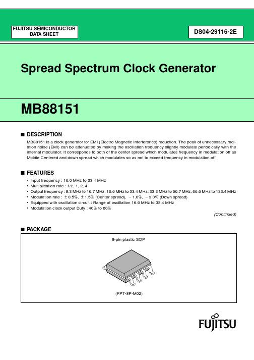
MB88151
■ PIN SETTING
When changing the pin setting, the stabilization wait time for the modulation clock is required. The stabilization wait time for the modulation clock take the maximum value of “■ ELECTRICAL CHARACTERISTICS • AC characteristics Lock-Up time”.
MB88151-400
: Less than 150 ps
MB88151-500
: Less than 200 ps
• Low current consumption by CMOS process : 5 mA (24 MHz : Typ-sample, no load)
• Power supply voltage : 3.3 V ± 0.3 V
PLL block
Clock output
CKOUT
XIN
Rf = 1 MΩ
VSS
1 − M
Reference clock 1
− N
Phase compare
Charge pump
V/I conversion
IDAC
Loop filter
ICO
Modulation clock output
1
Modulation
SEL0, SEL1 Modulation rate setting
SEL1
SEL0
L
L
L
BM85调试
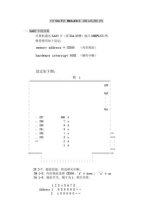
可编程BM85调试报告一、SA85卡的安装计算机通过SA85卡(需ISA插槽)接入MBPLUS网。
推荐使用如下设定:memory address = CE800 (内存地址)hardware interrupt NONE (硬件中断)设定如下图:图 1|-----------------------------------------------------------|| LED || || NA8 || . || . || . || NA1 || || .. IR7 SM8 d || .. IR6 7 u || .. IR5 6 d || .. IR4 5 u || .. IR3 4 u |-+ | .. IR2 3 u |+-+ | -- 2 d | | | 1 d | | | |+-+ +--------- -------------|-+ | || | | | | | | | | | | | | | | | | | | |IR 2-7: 最低短接,即选择无中断。
SM 1-8: 内存地址选择 CE800. 'd' = down ; 'u' = up NA 1-8: 地址开关。
朝左为1,朝右为零。
1 2 3 4 5 6 7 8Address 1 0 0 0 0 0 0 - -2 1 0 0 0 0 0 - -3 0 1 0 0 0 0 - -4 1 1 0 0 0 0 - -. . . . . . . . . .63 0 1 1 1 1 1 - -64 1 1 1 1 1 1 - -SA85卡的驱动程序有16位和32位两种。
此次调试在NT Workstation4.0上进行。
由于下载软件bm85load.exe需要16位驱动程序(在DOS下格式为:bm85load /s5c /re000 /p4.4 bm85.exe) 。
所以需安装SA85卡的16位驱动程序。
MB16AC可移动USB监视器混合信号解决方案用户指南说明书
MB16ACPortable USB Monitor Hybrid Signal SolutionUser GuideCopyright © 2017 ASUSTeK COMPUTER INC. All Rights Reserved.No part of this manual, including the products and software described in it, may be reproduced, transmitted, transcribed, stored in a retrieval system, or translated into any language in any form or by any means, except documentation kept by the purchaser for backup purposes, without the express written permission of ASUSTeK COMPUTER INC. (“ASUS”).Product warranty or service will not be extended if: (1) the product is repaired, modified or altered, unless such repair, modification of alteration is authorized in writing by ASUS; or (2) the serial number of the product is defaced or missing.ASUS PROVIDES THIS MANUAL “AS IS” WITHOUT WARRANTY OF ANY KIND, EITHER EXPRESS OR IMPLIED, INCLUDING BUT NOT LIMITED TO THE IMPLIED WARRANTIES OR CONDITIONS OF MERCHANTABILITY OR FITNESS FOR A PARTICULAR PURPOSE. IN NO EVENT SHALL ASUS, ITS DIRECTORS, OFFICERS, EMPLOYEES OR AGENTS BE LIABLE FOR ANY INDIRECT, SPECIAL, INCIDENTAL, OR CONSEQUENTIAL DAMAGES (INCLUDING DAMAGES FOR LOSS OF PROFITS, LOSS OF BUSINESS, LOSS OF USE OR DATA, INTERRUPTION OF BUSINESS AND THE LIKE), EVEN IF ASUS HAS BEEN ADVISED OF THE POSSIBILITY OF SUCH DAMAGES ARISING FROM ANY DEFECT OR ERROR IN THIS MANUAL OR PRODUCT.SPECIFICATIONS AND INFORMATION CONTAINED IN THIS MANUAL ARE FURNISHED FOR INFORMATIONAL USE ONLY, AND ARE SUBJECT TO CHANGE AT ANY TIME WITHOUT NOTICE, AND SHOULD NOT BE CONSTRUED AS A COMMITMENT BY ASUS. ASUS ASSUMES NO RESPONSIBILITY OR LIABILITY FOR ANY ERRORS OR INACCURACIES THAT MAY APPEAR IN THIS MANUAL, INCLUDING THE PRODUCTS AND SOFTWARE DESCRIBED IN IT.Products and corporate names appearing in this manual may or may not be registeredtrademarks or copyrights of their respective companies, and are used only for identification or explanation and to the owners’ benefit, without intent to infringe.Table of contentsNotices .........................................................................................................iii Safety information ......................................................................................iv Care & cleaning ............................................................................................v Takeback services ......................................................................................vi Caution ........................................................................................................vi 1.1 Welcome! ......................................................................................1-11.2 Package contents .........................................................................1-11.3Monitor introduction ....................................................................1-21.3.1 Front view .......................................................................1-21.3.2 QuickFit Function ............................................................1-32.1 Monitor standing positions .........................................................2-12.2 Connect the USB monitor with system ......................................2-22.3 Announcements ...........................................................................2-33.1OSD (On-Screen Display) menu .................................................3-13.1.1 How to reconfigure ..........................................................3-13.1.2 OSD Function Introduction ..............................................3-23.2 Specifications .............................................................................3-103.3 Troubleshooting (FAQ) ..............................................................3-113.4Supported Timing List ...............................................................3-13NoticesFederal Communications Commission StatementThis device complies with Part 15 of the FCC Rules. Operation is subject to the following two conditions:• This device may not cause harmful interference, and• This device must accept any interference received including interference that may cause undesired operation.This equipment has been tested and found to comply with the limits for a Class B digital device, pursuant to Part 15 of the FCC Rules. These limits are designed to provide reasonable protection against harmful interference in a residential installation. This equipment generates, uses and can radiate radio frequency energy and, if not installed and used in accordance with manufacturer’s instructions, may cause harmful interference to radio communications. However, there is no guarantee that interference willnot occur in a particular installation. If this equipment does cause harmful interference to radio or television reception, which can be determined by turning the equipment off and on, the user is encouraged to try to correct the interference by one or more of the following measures:• Reorient or relocate the receiving antenna.• Increase the separation between the equipment and receiver.• Connect the equipment to an outlet on a circuit different from that to which the receiver is connected.• Consult the dealer or an experienced radio/TV technician for help. Canadian Department of Communications StatementThis digital apparatus does not exceed the Class B limits for radionoise emissions from digital apparatus set out in the Radio Interference Regulations of the Canadian Department of Communications.This class B digital apparatus complies with Canadian ICES-003.As an Energy Star® Partner, our company has determinedthat this product meets the Energy Star® guidelines forenergy efficiency.Safety information• Before setting up this Portable USB Monitor, carefully read all the documentation that came with the package.• To prevent fire or shock hazard, never expose this Portable USB Monitor to rain or moisture.• Never try to open this Portable USB Monitor cabinet.• Before using this Portable USB Monitor, make sure all cables are correctly connected and the power cables are not damaged. If youdetect any damage, contact your dealer immediately.• Avoid dust, humidity, and temperature extremes. Do not place this Portable USB Monitor in any area where it may become wet. Place this Portable USB Monitor on a stable surface.• Never push objects or spill liquid of any kind into the slots on this Portable USB Monitor cabinet.• If you encounter technical problems with this Portable USB Monitor, contact a qualified service technician or your retailer.• This Portable USB Monitor is powered by USB port which complies with LPS and SELV circuit according to IEC60950-1:2005.Care & cleaning• Cleaning. Turn your monitor off and unplug the cable. Clean the monitor surface with a lint-free, non-abrasive cloth. Stubborn stainsmay be removed with a cloth dampened with mild cleaner.• Avoid using a cleaner containing alcohol or acetone. Use a cleaner intended for use with the LCD. Never spray cleaner directly on thescreen, as it may drip inside the monitor and cause an electric shock. The following symptoms are normal with the monitor:• You may find slightly uneven brightness on the screen depending on the desktop pattern you use.• When the same image is displayed for hours, an afterimage of the previous screen may remain after switching the image. The screen will recover slowly or you can turn off the Power Switch for hours.• When the screen becomes black or flashes, or cannot work anymore, contact your dealer or service center to fix it. Do not repair the screen by yourself!Conventions used in this guideWARNING: Information to prevent injury to yourself when trying tocomplete a task.CAUTION: Information to prevent damage to the componentswhen trying to complete a task.IMPORTANT: Information that you MUST follow to complete atask.NOTE: Tips and additional information to aid in completing a task.Where to find more informationRefer to the following sources for additional information and for product and software updates.1. ASUS websitesThe ASUS websites worldwide provide updated information on ASUS hardware and software products. Refer to 2. Optional documentationYour product package may include optional documentation that may have been added by your dealer. These documents are not part ofthe standard package.Takeback servicesASUS recycling and takeback programs come from our commitment to the highest standards for protecting our environment. We believe in providing solutions for our customers to be able to responsibly recycle our products, batteries and other components as well as the packaging materials. Please go to /english/Takeback.htm for detail recycling information in different region.CautionWe suggest to use the attached pen or any pen or stick that can fit in the hole at the corner as a simple stand for the monitor.Please reserve at least 10cm/4 inch of the pen at the back of the monitor to stabilize.1.1 Welcome!Thank you for purchasing the ASUS® Portable USB Monitor!The latest ASUS Portable USB Monitor provides great portability and simplicity to your daily life, enhancing both of your viewing experience and style.1.2 Package contentsCheck your package for the following items:Portable USB MonitorQuick Start GuideWarranty CardUSB Type-C CableSmart coverUSB Type-C to A adapterPen• If any of the above items is damaged or missing, contact your retailerimmediately.• Inbox pen is not included in the warranty.1.3Monitor introduction1.3.1Front view1. Pen hole •Use the attached pen to insert into the hole, the monitor can stand up directly without the smart cover.2. Power button/Power LED • Press this button to turn the monitor on/off.•The color definition of the power indicator is as the below table. 3. Menu button • Press this button to enter the OSD menu.4. Blue light filter •Adjust the energy level of blue light emitted from LED backlight.5.USB Type-C port1.3.2QuickFit FunctionThe QuickFit function contains two patterns: (1) Grid (2) Photo size.1.Grid pattern: Facilitates designers and users to organize content and layout on one page and achieve a consistent look and feel.Alignment grid 1 will be rotated automatically if auto rotation is enabled.•Auto rotation function is only working under Windows OS by installing DisplayWidget software.Alignment Grid22.Photo size: Provides photographers and other users to accurately view and edit their photos in real size on the screen.2.1 Monitor standing positionsYou can stand up the monitor by several positions with the smart cover.2.2Connect the USB monitor with systemorIn case the computer does not support Type-C interface but only USB3.0 interface, please install the official driver from ASUS website firstly.Please make sure the USB Type-C cable and Type-C to A adapter is connected between the USB monitor and the system.• Please check ASUS website for latest driver and DisplayWidget software.2.3 AnnouncementsAs this product and attached smart cover includes magnet in the structure, there could be potential risk to cause the damage of computer hard disc and objects that are sensitive to magnet.3.1OSD (On-Screen Display) menu3.1.1How to reconfigure1. Press the MENU button to activate the OSD menu.2. Press the ❑ button to toggle between options in the Menu. As you move from one icon to another, the option name is highlighted.3. To select the highlighted item on the menu press the button.4. Press the ❑ button to select the desired parameter.5.Press the button to enter the slide bar and then use the ❑ button, according to the indicators on the menu, to make your changes.6.to accept and returnto previous menu.3.1.2 OSD Function Introduction1. SplendidThis function contains eight sub-functions that you can select for your preference.: This is the best choice for document editing with SPLENDID™ Video Intelligence Technology.• sRGB Mode : This is the best choice for viewing photos and graphics from PCs.• Scenery Mode : This is the best choice for scenery photo displaying with SPLENDID™ Video Intelligence Technology.• Theater Mode : This is the best choice for movie watching with SPLENDID™ Video Intelligence Technology.• Game Mode : This is the best choice for game playing with SPLENDID™ Video Intelligence Technology.•Night View Mode : This is the best choice for playing dark-scene game or watching dark-scene movie with SPLENDID™ Video Intelligence Technology.• Reading Mode : This is the best choice for book reading.•Darkroom Mode : This is the best choice for a weak ambient light environmen.• In the Standard Mode, the Saturation, SkinTone, Sharpness, and ASCR functions are not user-configurable.• In the sRGB, the Saturation, Color Temp., SkinTone, Sharpness, Brightness, Contrast and ASCR functions are not user-configurable.•In the Reading Mode, the Saturation, SkinTone, Sharpness, ASCR, contrast, and Color Temp functions are not user-configurable.2.Blue Light FilterAdjust the energy level of blue light emitted from LED backlight.• Level 0: No change.•Level 1~4: The higher the level,the more blue light will be reduced.• When Blue Light Filter is activated,the default settings of Standard Mode will be automatically imported.• Between Level 1 to Level 3, the Brightness function is user-configurable.• Level 4 is optimized setting. It is compliance with TUV Low Blue Light Certification. The Brightness function is not user-configurable.•To alleviate eye strain, rest your eyes for fifteen minutes for every two hours spent in front of the screen. Frequent blinking and eye exercise helps keep your eye moist to prevent them from drying out. In addition, your computer screen should be placed 20 to 28 inches (50-70cm) away from you.3. ColorSelect the image color you like from this function.• Brightness : The adjusting range is from 0 to 100.• Contrast : The adjusting range is from 0 to 100. • Saturation : The adjusting range is from 0 to 100.• Color Temp.: Contains three preset color modes (Cool , Normal , Warm )and User Mode.•Skin Tone : Contains three color modes including Reddish , Natural , and Yellowish .•In the User Mode, colors of R (Red), G (Green), and B (Blue) are user-configurable; the adjusting range is from 0 ~ 100.4. ImageYou can adjust the image Sharpness, Trace Free, Aspect Control, VividPixel and ASCR from this main function.• Sharpness : Adjusts the picture sharpness. The adjusting range is from 0 to 100.• Trace Free : Speeds up the response time by Over Drive technology. The adjusting range is from lower 0 to faster 100.• Aspect Control : Adjusts the aspect ratio to “Full ”, “4:3”,“1:1”. •VividPixel: ASUS Exclusive Technology that brings lifelike visuals for crystal-clear and detail-oriented enjoyment. The adjusting range is from 0 to 100.•ASCR : Select ON or OFF to enable or disable dynamic contrast ratio function.•4:3 is only available when input source is in 4:3 format .5. System SetupAdjusts the system configuration.• Splendid Demo Mode: Activate the demo mode for the Splendid function.• Auto Rotation: To enable/disable rotate image automatically.Please be noted that Auto rotation function is only working under Windows OS byinstalling DisplayWidget software• GamePlus: The GamePlus Function provides a toolkit and creates a better gaming environment for users when playing different types ofgames. Particularly, Chrosshair function is specially designed for newgamers or beginners interested in First Person Shooter (FPS) games.To active GamePlus:• Select ON to enter the GamePlus main menu.• Press to select between Chrosshair, Timer and Display Alignment function.• Press to confirm the function you choose. Select to go off, and exit.GamePlus-Timer• QuickFit: See page 1-3 for details.• ECO Mode: Activate the ecology mode for power saving.• OSD Setup: Adjusts the OSD Timeout, DDC/CI, and Transparency of the OSD screen.• Language: Select OSD language. The selections are: English, French, German, Spanish, Italian, Dutch, Russian, Poland, Czech, Croatia, Hungary, Romania, Portugal, Turkey, Simplified Chinese, Traditional Chinese, Japanese, Korean, Persian, Thai and Indonesian.• M ore: Return the next page of System Setting.• Key Lock: Disable all key functions. Pressing the menu button for more than five seconds to disable key lock function.• I nformation:Displays the monitor information.• Power Indicator: Turn the power LED indicator on/off.• Power Key Lock: To disable / enable power key.• All Reset: Selects “Yes” to revert all settings to the factory default mode.6. ShortcutSelecting this option allows you to set shortcut key.• Shortcut : User can select from “Blue Light Filter” “Splendid”, “Brightness”, “Contrast”, “Auto Rotation”, “Color Temp.”,“QuickFit”, “GamePlus” and set as shortcut key.7. MyFavoriteLoad/Save all settings on the monitor.3.2 Specifications*Specifications are subject to change without notice.3.3 Troubleshooting (FAQ)*1: White color background will consume higher power, so it’s better to use white color background to test the power limit from source USB Type-C device.*2: If MB16AC does not re-start when adjusting to value 100, that meanssource USB Type-C device has sufficient power supply.3.4 Supported Timing List。
dynamo全部节点中文翻译

Cuboid (['kjubɔɪd]立方体)
Curtain (['kɝtn]窗帘、幕墙)
Curve ([kɝv]n. 曲线;弯曲)
Cylinder (['sɪlɪndə]n. 圆筒;圆柱)
Data (['detə]数据(datum的复数);资料)
Date ([det]:日期)
Daylighting (daylight['delaɪt]:白天;日光;黎明;公开。
Delaunay 三角网
)采光
60 Directory ([daɪ'rɛktəri]目录) 43 Display ([dɪ'sple]n. 显示;表现;炫耀。vt. 显示;表现) 105 Divided ([dɪ'vaɪdɪd]分开、分离、分割) 29 division ([də'vɪʒən]除法,分割,分格) 18 Document (['dɒkjʊm(ə)nt]:文档、文件) 136 Drafting (['drɑːftɪŋ]起草、制图、工程图) 70 Edge ([ɛdʒ]边线) 96 element (['ɛləmənt]图元、要素、元素、成分) 112 Elevation ([,elɪ'veɪʃ(ə)n]高地、海拔、高程、立面图) 71 Ellipse ([ɪ'lɪps]椭圆) 15 Environment ([ɪn'vaɪrənmənt]:环境) 25 Equal (['ikwəl]平等的,相等的) 47 Evaluate ([ɪ'væljʊ'et]评价) 17 Export ([ˈekspɔːrt;ɪkˈ-]:输出、出口) 3 Extensions ([ɪk'stɛnʃən]扩展、扩张) 72 Face ([fes]面) 59 File ([faɪl]n. 文件;档案) 109 Floor ([flɔː]楼板、地面、楼层) 35 foot ([fʊt]n. 脚;英尺) 123 Footing (['fʊtɪŋ]基础) 110 Form ([fɔːm]形式、形状、表格) 48 Formula (['fɔrmjələ]n. [数] 公式,准则;配方) 119 Framing (['fremɪŋ]框架、设计) 44 Geometry ([dʒɪ'ɑmətri]n. 几何学,几何结构) 30 grid ([ɡrɪd]n. 网格;格子,栅格;输电网) 75 group ([gruːp]组) 38 Height ([haɪt]高度) 73 Helix (['hilɪks]螺旋) 92 Hull ([hʌl]外壳) 13 Illuminance ([ɪ'lumɪnəns]照明度) 34 image (['ɪmɪdʒ]n. 影像;想象) 111 Import (['ɪmpɔt]输入、导入) 74 Index (['ɪndeks]索引) 39 information ([ɪnfə'meɪʃ(ə)n]信息) 49 Input (['ɪn'pʊt]输入) 107 Instance (['ɪnstəns]实例、实体) 11 Job ([dʒɒb]:工作) 4 Label (Label['lebl]:标签、标注)
Modbus协议规范中文版

2
~~~~~~~~~~~~~~~~~~~~~~~~~~~~~~~~~~~~~~~ @ 珠联璧合 xlzhu xlzhu@
Modbus 协议规范中文版
~~~~~~~~~~~~~~~~~~~~~~~~~~~~~~~~~~~~~~~
主处理器 MAP
984-685 (到 MB PLUS) S980(到 MAP) Modbus Plus
信息帧功能代码包括字符(ASCII)或 8 位(RTU)。有效码范围 1-225(十进制),其中有 些代码适用全部型号的 Modicon 控 制器, 而有些代码仅适用于某些型号的控制器。 还有一 些代码留作将来使用,有关功能代替码的设置将在第 2 章说明。 当主机向从句发送信息时, 功能代码向从机说明应执行的动作。 如读一组离散式线圈或 输入信号的 ON/OFF 状态, 读 一组寄存器的数据, 读从机的诊断状态, 写线圈 (或寄存器) , 允许下截、记录、确认从机内的程序等。当从机响应主机时, 功能代码可说明从机正常响 应或出现错误(即不正常响应),正常响应时,从句简单返回原始功能代码;不正常响应时, 从机 返回与原始代码相等效的一个码,并把最高有效位设定为“1” 。 如,主机要求从机读一组保持寄存器时,则发送信息的功能码为: 0000 0011 (十六进制 03) 若从机正确接收请求的动作信息后,则返回相同的代码值作为正常响应。发现错时, 则 返回一个不正常响信息: 1000 0011(十六进制 83) 从机对功能代码作为了修改,此外,还把一个特殊码放入响应信息的数据区中,告诉主 机出现的错误类型和不正常响 应的原因。主机设备的应用程序负责处理不正常响应,典型 处理过程是主机把对信息的测试和诊断送给从机,并通知操作者。 1.3.5 数据区的内容
例外:对于 584 和 984A/B/X 控制器,一个 ASCII 信息可在 LRC 区后正常终止,而 不需发送 CRLF 字符,此时出现>IS 的时 间间隔,控制器也将认为是正常中断。 1.3.2 RTU 帧
- 1、下载文档前请自行甄别文档内容的完整性,平台不提供额外的编辑、内容补充、找答案等附加服务。
- 2、"仅部分预览"的文档,不可在线预览部分如存在完整性等问题,可反馈申请退款(可完整预览的文档不适用该条件!)。
- 3、如文档侵犯您的权益,请联系客服反馈,我们会尽快为您处理(人工客服工作时间:9:00-18:30)。
LSB
催䰏ᡫ
DS501-00014-2v0-Z
9
MB85RS16
• RDID
RDID 命令读取固定的器件 ID。执行 RDID 操作码到 SI 之后,32 周期时钟输入 SCK。SI 值此时无效。SO 同步输出到 SCK 的下降沿。输出顺序是制造商 ID(8 位)/ 继续代码(8 位)/ 产品 ID(第 1 个字节)/ 产 品 ID (第 2 个字节)。 在 RDID 命令中,通过在 CS 上升之前连续发送 SCK 时钟, SO 在 32 位器件 ID 输出之后保持最后一位的 输出状态。
名称
描述
操作码
WREN
设置写使能锁存器
0000 0110B
WRDI
复位写使能锁存器
0000 0100B
RDSR
读状态寄存器
0000 0101B
WRSR
写状态寄存器
0000 0001B
READ
读内存代码
0000 0011B
WRITE
写内存代码
0000 0010B
RDID
读器件 ID
1001 1111B
MB85RS16
■ 引脚分配
CS SO WP GND
( 顶视图 ) 1 2 3 4
8
VDD
7
HOLD
6
SCK
5
SI
(FPT-8P-M02)
■ 引脚功能描述
引脚编号 引脚名称
功能描述
芯片选择引脚
这是进行芯片选择的输入引脚。当 CS 为 “高”电位时,器件处于取消选择 (等待)状
1
CS 态, SO 成为高阻抗状态。这次会忽略从其他引脚的输入。 CS 为 “低”电平时,器件
CS SCK SI SO
0 1 2 3 4 5 6 7 8 9 10 11 12 13
18 19 20 21 22 23 24 25 26 27 28 29 30 31
操作码
16 位地址
᭄䕧ܹ
0 0 0 0 0 0 1 0 X X X X X 10
543210 76543210
MSB
LSB MSB
CS
SCK SI SO
012345670 1 2 3 4 5 6 7
ᣛҸ
᭄䕧ܹ
0000000176543210
MSB
LSB
催䰏ᡫ
8
DS501-00014-2v0-Z
MB85RS16
• READ
READ 命令读取 FRAM 存储单元阵列数据。任意 16 位地址和 READ 的操作码输入 SI。5 位高地址位无效。 然后, 8 周期时钟输入 SCK。 SO 同步输出到 SCK 的下降沿。读取时, SI 值无效。当 CS 上升时, READ 命令完成,但以自动地址递增的方式持续读取 (通过在 CS 上升之前以 8 周期为单位连续发送时钟到 SCK 实现)。当到达最重要的地址时翻转到起始地址,并无限保持读取周期。
WEL
WPEN
WP
保护块
非保护块
状态寄存护
保护
1
0
X
保护
非保护
非保护
1
1
0
保护
非保护
保护
1
1
1
保护
非保护
非保护
■ 保持操作
如果 HOLD 是 “低”电平而 CS 是 “低”电平,那不需要放弃命令即可保留保持状态。起始和结束时序的 保持状态取决于当 HOLD 引脚输入转换到保持条件时 SCK 是 “高”电平还是 “低”电平,如下图所示。 在 SCK 为 “低”电平时 HOLD 引脚转换为 “低”电平的情况下,在 SCK 为 “低”电平时将 HOLD 引脚 返回到 “高”电平。以此类推,在 SCK 为 “高”电平时 HOLD 引脚转换为 “低”电平的情况下,在 SCK 为 “高”电平时将 HOLD 引脚返回到 “高”电平。任意命令操作在保持状态时都会中断, SCK 和 SI 输入 变为可忽略。而且,SO 在读取命令(RDSR, READ 时变为高阻抗)。如果 CS 在保持状态期间上升,则命 令会中止。在命令识别前即被中止的情况下, WEL 会在转换为 HOLD 状态之前保持值。
7
HOLD
该引脚用于在无需进行芯片取消选择的情况下中断串行输入 / 输出。 HOLD 处于 “低” 电平时,保持操作被激活,SO 成为高阻抗状态,SCK 和 SI 成为可忽略状态。在保持操
作时, CS 必须保留为 “低”电平。
串行时钟引脚
6
SCK 时钟输入引脚,用于输入 / 输出串行数据。 SI 同步加载至上升沿, SO 同步输出至下降
■ 块保护
WRITE 命令的写保护块由状态寄存器中 BP0 和 BP1 的值配置。
BP1
BP0
保护块
0
0
无
0
1
600H 到 7FFH (高位 1/4)
1
0
400H 到 7FFH (高位 1/2)
1
1
000H 到 7FFH (全部)
■ 写保护
WRITE 命令和 WRSR 命令的写操作通过 WEL、 WPEN、 WP 的值保护,如表中所示。
CS SCK SI SO
0 1 2 3 4 5 6 7 8 9 10 11 12 13
18 19 20 21 22 23 24 25 26 27 28 29 30 31
操作码
16 位地址
0 0 0 0 0 0 1 1 X X X X X 10
MSB
催䰏ᡫ
543210 LSB MSB
76
᮴ᬜ ᭄䕧ߎ LSB
SCK MOSI MISO
SPI 微控制器
SS1 SS2 HOLD1 HOLD2
SO SI SCK MB85RS16
CS
HOLD
使用 SPI 端口的系统配置
SO SI SCK MB85RS16
CS
HOLD
MOSI : 主输出从输入 MISO : 主输入从输出 SS : 从选择
微控制器
SO SI SCK MB85RS16
密度
产品 ID (第 1 个字节) 0 0 0 0 0 0 0
专利使用 产品 ID (第 2 个字节) 0 0 0 0 0 0 0
0
十六 进制
0 04H Fujitsu
1 7FH
十六 进制
1 01H 密度:00001B = 16k 位
十六 进制
1 01H
10
DS501-00014-2v0-Z
MB85RS16
І㸠-ᑊ㸠䕀ᤶ఼
CS SCK HOLD WP
SO
ᑊ㸠-І㸠䕀ᤶ఼
ࠊ⬉䏃 ഄഔ䅵ㅫ఼ 㸠䆥ⷕ఼
MB85RS16
FRAM ऩܗ䰉߫ 2,048 × 8 FRAM ⢊ᗕᆘᄬ఼ ߫䆥ⷕ఼/♉ᬣᬒ఼/ ݭᬒ఼
᭄ᆘᄬ఼
DS501-00014-2v0-Z
3
MB85RS16
■ SPI 模式
MB85RS16 与 SPI 模式 0 (CPOL = 0, CPHA = 0) 和 SPI 模式 3 (CPOL = 1, CPHA = 1) 通信。
6
DS501-00014-2v0-Z
MB85RS16
■ 命令
• WREN
WREN 命令设置 WEL (写使能锁存器)。 WEL 需要在写操作 (WRSR 命令和 WRITE 命令)之前使用 WREN 命令设置。
CS SCK
0
1
2
3
4
5
6
7
SI
᮴ᬜ
0
0
0
0
0
1
1
0
催䰏ᡫ SO
᮴ᬜ
• WRDI WRDI 命令重置 WEL (写使能锁存器)。写操作 (WRITE 命令和 WRSR 命令)在 WEL 重置时不会执行。
沿。
5
SI
串行数据输入引脚 这是串行数据的输入引脚。用于输入操作码、地址和写数据。
串行数据输出引脚
2
SO 这是串行数据的输出引脚。读取 FRAM 存储单元阵列和状态的数据寄存器数据是输出。
等待期间为高阻抗状态。
8
VDD 电源电压引脚
4
GND 接地引脚
2
DS501-00014-2v0-Z
■ 方块图
SI
未使用位 这些是由非易失性存储组成的位,可以使用 WRSR 命令写入。这些位未 使用,但可以使用 RDSR 命令读取。
块保护 该位由非易失性存储组成。这定义了 WRITE 命令的写保护块的大小 (参 见 “■ 块保护”)。可以使用 WRSR 命令写入和使用 RDSR 命令读取。
写使能锁存器 这表示 FRAM 阵列和状态寄存器是可写的。 WREN 命令用于设置,而 WRDI 命令用于重置。使用 RDSR 命令可以读取,但用 WRSR 命令不能 写入。 WEL 会在以下操作之后重置。
CS
HOLD
不使用 SPI 端口的系统配置
DS501-00014-2v0-Z
5
MB85RS16
■ 状态寄存器
位编号
位名称
7
WPEN
6到4
−
3
BP1
2
BP0
1
WEL
0
0
功能
状态寄存器写保护 该位由非易失性存储 (FRAM) 组成。 WPEN 保护与 WP 输入相关的状态 寄存器写入 (参见 “■ 写保护”)。可以使用 WRSR 命令写入和使用 RDSR 命令读取。
打开电源后。 WRDI 命令识别后。 WRSR 命令识别后 CS 的上升沿。 WRITE 命令识别后 CS 的上升沿。
这是固定为 “0”的位。
■ 操作码