功率放大器模块PAM06说明书20191025
PA6002广带RF线性功率放大器用户说明书
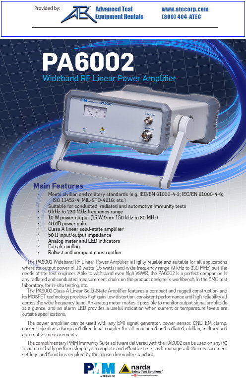
The PA6002 Wideband RF Linear Power Amplifier is highly reliable and suitable for all applications where its output power of 10 watts (15 watts) and wide frequency range (9 kHz to 230 MHz) suit the needs of the test engineer. Able to withstand even high VSWR, the PA6002 is a perfect companion in any radiated and conducted measurement chain: on the product designer’s workbench, in the EMC test laboratory, for in-situ testing, etc.The PA6002 Class A Linear Solid-State Amplifier features a compact and rugged construction, and its MOSFET technology provides high gain, low distortion, consistent performance and high reliability all across the wide frequency band. An analog meter makes it possible to monitor output signal amplitude at a glance, and an alarm LED provides a useful indication when current or temperature levels are outside specifications.The power amplifier can be used with any EMI signal generator, power sensor, CND, EM clamp, current injections clamp and directional coupler for all conducted and radiated, civilian, military and automotive measurements .The complimentary PMM Immunity Suite software delivered with the PA6002 can be used on any PC to automatically perform simple yet complete and effective tests, as it manages all the measurement settings and functions required by the chosen immunity standard .Wideband RF Linear Power AmplifierMain Features•Meets civilian and military standards (e.g. IEC/EN 61000-4-3; IEC/EN 61000-4-6; ISO 11452-4; MIL-STD-461G; etc.)•Suitable for conducted, radiated and automotive immunity tests •9 kHz to 230 MHz frequency range•10 W power output (15 W from 150 kHz to 80 MHz) •40 dB power gain•Class A linear solid-state amplifier •50 Ω input/output impedance • Analog meter and LED indicators • Fan air cooling•Robust and compact constructionOrdering information:PA6002 Wideband RF Linear Power AmplifierIncludes: Power supply cable, BNC-BNC cable, N-m to BNC-f adapter, user’s manual, standard calibration certificateOptional accessories:3010 EMI Signal Generator 9 kHz to 1 GHz3030-01 EMI Signal Generator 9 kHz to 3 GHz, AC supply3030-02 EMI Signal Generator 9 kHz to 3 GHz, AC supply, internal rechargeable battery 6630 USB RF Power Sensor 9 kHz to 3 GHz 6630 FOA Fiber Opic AdapterEP-600 Field probe 100 kHz to 9,25 GHz 0,14 to 140 V/m EP-601 Field probe 10 kHz to 9,25 GHz 0,5 to 500 V/m EP-602 Field probe 5 kHz to 9,25 GHz 1,5 to 1500 V/m EP-603 Field probe 300 kHz to 18 GHz 0,17 to 170 V/m EP-604 Field probe 300 kHz to 26,5 GHz 0,4 to 800 V/m OR03 Optical Programmable Repeater and its probes SB-10 Switching control boxEM Clamps, Current injections clamps, Directional couplers, CDN for mains, Unshielded/ Unbalanced lines CDNs, Shielded lines CDNs, Balanced lines CDNs, 6 dB attenuators, CDN calibration kit and accessories ; for full list and configurations please refer to COND-IS and RAD-IS system documentationGenerators/Receivers/SystemsAntennas/Calibration servicesLISNs/Probes• 1008: Magnetic field generator system • 7010/00: EMI Receiver 150 kHz to 1 GHz • 7010/01: EMI Receiver 9 kHz to 1 GHz • 7010/02: EMI Receiver 9 kHz to 30 MHz • 7010/03: EMI Receiver 9 kHz to 3 GHz • 9010: EMI Receiver 10 Hz to 30 MHz • 9010F: EMI Receiver 10 Hz to 30 MHz• 9010/03P: EMI Receiver 10 Hz to 300 MHz • 9010/30P: EMI Receiver 10 Hz to 3 GHz • 9010/60P: EMI Receiver 10 Hz to 6 GHz • 9030: EMI Receiver 30 MHz to 3 GHz • 9060: EMI Receiver 30 MHz to 6 GHz • 9180: EMI Receiver 6 GHz to 18 GHz • FR4003: Field Receiver 9 KHz to 30 MHz • COND-IS: RF Conducted Immunity System • RAD-IS: RF Radiated Immunity System •AUT-IS: Automotive Immunity System• BC-01: Biconical Antenna 30 to 200 MHz• DR-01: Double-ridged horn Antenna 6 to 18 GHz • LP-02: Log Periodic Antenna 200 MHz to 3 GHz • LP-03: Log Periodic Antenna 800 MHz to 6 GHz • LP-04: Log Periodic Antenna 200 MHz to 6 GHz • TR-01: 60-180 cm wooden extendable tripod• VDH-01: Van der Hoofden Test Head 20 kHz to 10 MHz • Antenna Set AS-02 (BC01+LP02+TR01)• Antenna Set AS-03 (BC01+LP02+LP03+TR01) • Antenna Set AS-04 (BC01+LP04+TR01)• Antenna Set AS-05 (BC01+LP04+DR01+TR01)• RA-01: Rod Antenna 9 kHz to 30 MHz• RA-01-HV: Rod Antenna 150 kHz to 30 MHz • RA-01-MIL: Rod Antenna 9 kHz to 30 MHz • Ansi 63,5 Antenna Factor • SAE ARP 958-D• Free-Space Antenna Factor• CAL-6630: Traceable calibration •LAT-6630: Accredited calibration• L2-16B: single phase AMN, 16 A • L3-32: 4 lines, 3-phase AMN, 32 A • L3-64: 4 lines, 3-phase AMN, 63 A• L3-64/690V: 4 lines, 3-phase AMN, 63 A • L3-100: 4 lines, 3-phase AMN, 100 A• L1-150M: single-path, 50 Ohm AMN, 150 A • L1-150M1: single-path, 50 Ohm AMN, 150 A • L1-500: single phase AMN, 500 A • L3-500: 4 lines, 3-phase AMN, 500 A • L2-D: Delta LISN for telecom, 2 A, 150 Ω• RF-300: Van Veen Loop • SBRF4: RF Switching Box• SHC-1/1000: Voltage probe, 1000 Vac, 35 dB • SHC-2/1000: Voltage probe, 1000 Vac, 30 dBRelated products and servicesP A 6002-F E N -70501 - S p e c i fi c a t i o n s s u b j e c t t o c h a n g e w i t h o u t n o t i c eHeadquarters:Via Benessea, 29/B17035 Cisano sul Neva (SV) - ITALY Phone: +39 0182 58641Fax: +39 0182 586400E-Mail:***********************Internet: www.narda-sts.itSales:Via Leonardo da Vinci, 21/2320090 Segrate (Milano) - ITALY Phone: +39 02 2699871Fax: +39 02 26998700PA6002Wideband RF Linear Power AmplifierSPECIFICATIONSFrequency range Power output CW Power gain Gain flatness Drive levelInput return loss Harmonic distortion RF input RF outputPower indication LED indicators Power supplyOperating temperature Operating humidity Storage temperature Dimensions (W x H x D)Weight9 kHz to 230 MHz10 W; 15 W from 150 kHz to 80 MHz 40 dB+1 dB -1,5 dB0 dBm (1 mW) for 10 W output < 20 dB < -20 dBcZin 50 Ω, BNC female Zin 50 Ω, N female Analog meter, 20 W f.s.Power/current limiter and temperature alarm85 to 264 Vac 47 to 440 Hz / 120 to 370 Vdc 60W 0 °C to +40 °C0 to 90% RH (without condensation)-40 °C to +70 °C 235 x 105 x 300 mm 4,5 kgTypical gain @ nominal power (dB)Power output @ 1 dBc (W)。
MPU-6说明书

MPU-6型恒功率晶闸管中频电源控制板使用说明书大芯片六脉波1、概述MPU-6恒功率晶闸管中频电源控制板,是MPU-2基础上开发的新型控制触发板。
主要由电源、调节器、移相控制电路、保护电路、启动演算电路、逆变频率跟踪、逆变脉冲形成、脉冲放大及脉冲变压器组成。
其核心部件采用了高性能、高密度、超大规模专用MPU集成电路,使其电路除调节器外,其余均实现数字化,整流触发器部分不需要任何调整,而且可靠性高、脉冲对称度高、抗干扰能力强、反应速度快等特点,又由于有相序自适应电路,无需同步变压器,所以,现场调试中免去了调相序、对同步的工作,仅需把KP晶闸管的门极线接入控制板相应的接线端上,整流部分便能投入运行。
逆变采用扫频式零压软启动方式,启动性能优于普通的零压软启动电路。
并设有自动重复启动电路,可防止中频电源偶尔的启动失败,使启动成功率达到100%。
频率跟踪电路采用的是平均值取样方案,提高了逆变的抗干扰能力,而且仅需取样中频电压信号,而无需槽路电容器的电流信号,免去了外接中频电流互感器、确定取样电流相位的烦恼。
因此,在调试和使用现场中,也不会由于中频输出线或取样电流互感器的相位接反,而产生中频电源不能启动的问题。
逆变电路中还加有逆变角调节电路,可以自动调节负载阻抗的匹配,达到恒功率输出,可以制成“快速熔炼”的中频电源,达到节时、节电、提高网侧功率因数的目的(此功能也可被送掉)。
逆变部分的主要电路均在MPU大规模集成电路的内部,亦是数字电路。
MPU-6控制板全板仅有8只集成电路、4只晶体管、6只微调电位器、33个引出端子,安装十分方便,适用于各种晶闸管并联谐振中频电源。
2、产品名称产品名称:MPU-6恒功率晶闸管中频电源控制板3、适用装置适用于400HZ-10KHZ各种晶闸管并联谐振中频电源。
4、正常使用条件4.1海拔不超过2000米。
4.2环境温度不低于-10℃,不高于+40℃。
4.3空气最大相对湿度不超过90%(20℃±5℃时)。
PAA6频谱音频分析仪中文说明书

9
12. 支架连接器 位于PAA6的后侧。可连接三脚架或任意其它匹 配标准#6-20连接螺丝的支架。常见于相机三 脚架。此外PAA6还包括一个支架适配器,使得 PAA6可安装至麦克风支架。 13. 触控笔 PAA6的触控笔位于此狭槽内。不使用时请将触 控笔置于狭槽内以避免丢失。
简体中文
图8
● RTA模式小妙招:如果您发现多达一个或一个以上的声道持续出现峰值,请注意屏幕左侧的“dBS” 或“dBu”测量值(图9和10)。点击最上方的值(位于小方框中间)将向上滚动窗口,显示较高的读数——无 峰值出现。
图9
9
PAA6
简体中文
图 10
● 如果您需要在不触碰屏幕的情况下读取测量数据,请务必关闭背光功能的睡眠模式,否则数分钟(图 11)之后屏幕就会变暗。此设置可通过System—>Display菜单实现。
14 15
声道(MIC 1和MIC 2或Line 1和Line 2)。点击任 一一个,将启动或禁用对应声道。
8. 属性窗口 – 此窗口可显示接收的信号的属 性,通常为当前选择的频率段的电平(显示为dB SPL,dBu,dBV或Volt),峰值的频率和当前被 测量的单位。所使用的功能的不同,显示的结 果也不相同。
P h o n i c深谙放声管理的重要性。正如您的职 业,我们知道您首要,或许是唯一关心的是音 质。因此,拥有PA A6这样的音频工具,您即拥 有获得准确测量数据,以及任何专业人士所期 望的最佳音质的法宝。我们ቤተ መጻሕፍቲ ባይዱ证PA A 6是您搜 集所有必要的数据,并赖以决定设置音响系统 所需的最为精确和有效的工具。
rf6000-2 3v 900mhz 线性放大器模块 - 用户手册说明书

2-677Product DescriptionOrdering InformationTypical ApplicationsFeaturesFunctional Block DiagramRF Micro Devices, Inc.7628 Thorndike RoadGreensboro, NC 27409, USA Tel (336) 664 1233Fax (336) 664 0454Optimum Technology Matching® AppliedSi BJT GaAs MESFET GaAs HBTSi Bi-CMOS SiGe HBTSi CMOS InGaP/HBTGaN HEMTSiGe Bi-CMOSVREG GND VCC1RF OUT GND VCC2V M O D EGND RF IN G N DG N DGND GNDRF6000-23V 900MHZ LINEAR AMPLIFIER MODULE•3V CDMA/AMPS Cellular Handsets •3V CDMA2000/1X Cellular Handsets •Spread-Spectrum Systems •Designed for Compatibility with Qualcomm ChipsetsThe RF6000-2 is a high-power, high-efficiency linear amplifier module targeting 3V handheld systems. The device is manufactured on a RF Micro Devices’ advanced third generation Gallium Arsenide Heterojunction Bipolar T ransistor (HBT) process, and has been designed for use as the final RF amplifier in dual-mode 3V CDMA/AMPS handheld digital cellular equipment, spread-spectrum systems, and other applications in the 824MHz to 849MHz band. The RF6000-2 has a digital control line for low power application to reduce the current drain. The device is self-contained with 50Ω input and output that is matched to obtain optimum power, efficiency, and linear-ity characteristics. The module is an ultra-small 5mmx5mm land grid array with backside ground.•Advanced 3rd Generation HBT Process •Input/Output Internally Matched@50Ω•28.5dBm Linear Output Power•29dB Linear Gain•45mA Idle Current (Low Power Mode)•CDMA2000 CompatibleRF6000-23V 900MHz Linear Amplifier Module RF6000-2 PCBA Fully Assembled Evaluation BoardBottom View0.150 T 0.00.850 T 1.150 T 2.82.11.83.13.850 T 4.150 T 4.850 T Package Style: LGM (5mmx5mm)Preliminary !Preliminary2-678RF6000-2Absolute Maximum RatingsParameterRatingUnitSupply Voltage (RF off)+8.0V DC Supply Voltage (P OUT ≤31dBm)+5.2V DC Control Voltage (VREG )+4.2V DC Input RF Power+10dBm Mode Voltage (V MODE )+3.5V DC Operating Case Temperature -30 to +110°C Storage Temperature-30 to +150°CParameterSpecification Unit ConditionMin.Typ.Max.High Power State (V MODE Low)Typical Performance at V CC =3.4V ,V REG =2.85V, T AMB =25°C, Frequency=836MHz(unless otherwise specified)Frequency Range 824849MHz Linear Gain29dB Second Harmonic -35dBc Third Harmonic-35dBc Maximum Linear Output Power 2828.5dBm Low Voltage Linear OutputPower27dBm V CC =3.0VT otal Linear Efficiency 38%P OUT =28.5dBm (room temperature)T otal I CC530mA P OUT =28dBmAdjacent Channel PowerRejection -50-46dBc *************OUT =28dBm (IS-95)-61-58dBc**************OUT =28dBm (IS-95)Input VSWR 2:1Output VSWR 10:1No damage.6:1No oscillations. >-70dBc Noise Power-136dBm/HzAt 45MHz offset.Low Power State (V MODE High)Typical Performance at V CC =3.4V , V REG =2.85V, T AMB =25°C, Frequency=836MHz(unless otherwise specified)Frequency Range 824849MHz Linear Gain 20dB Second Harmonic -35dBc Third Harmonic -35dBc Maximum Linear Output Power 1820dBm T otal Current, I CC 180mA P OUT =18dBmAdjacent Channel Power Rejection-50-46dBc *************OUT =18dBm (IS-95)-70-58dBc**************OUT =18dBm (IS-95)Input VSWR 2:1Output VSWR10:1No damage.6:1No oscillations. >-70dBcESD sensitive device.RF Micro Devices believes the furnished information is correct and accurate at the time of this printing. However, RF Micro Devices reserves the right to make changes to its products without notice. RF Micro Devices does not assume responsibility for the use of the described product(s).Preliminary2-679RF6000-2CDMA2000 Configuration TableParameterSpecification UnitConditionMin.Typ.Max.FM ModeTypical Performance at V CC =3.4V ,V REG =2.85V, T AMB =25°C, Frequency=836MHz(unless otherwise specified)Frequency Range 824849MHz Gain28dB Second Harmonic -35dBc Third Harmonic-35dBc Max CW Output Power31.5dBm T otal Efficiency (AMPS mode)48%V CC =3.4V, V REG =2.85V , P OUT =31.5dBm (room temperature)Input VSWR 2:1Output VSWR10:1No damage.5:1No oscillations. >-70dBcDC SupplySupply Voltage Range 3.23.44.2V Quiescent Current 150mA V MODE =Low, V REG =2.85V 45mA V MODE =High, V REG =2.85VV REG Current 3mA V MODE Current 250µA T urn On/Off Time<40µsV REG switch from Low to High, I CC to within 90% of the final value, P OUT within 1dB of the final value T otal Current (Power Down)5µA V REG =Low, V MODE =LowV REG “Low” Voltage 00.5V V REG “High” Voltage 2.8 2.852.9V V MODE “Low” Voltage 00.5V V MODE “High” Voltage2.03.0VRelative GainsNo.ConfigurationPeak-to-Average CCDF=1%PCHDCCHFCHSCHTypical Maximum Output Power (dBm)1DCCH 96005.4-3.75026.52FCH 9600, SCH0 9600 4.5-3.750028.03DCCH 9600, SCH0 9600 4.5-3.750028.04FCH 9600, SCH0 19200 4.5-6.25-2.65028.05FCH 9600, SCH0 38400 4.3-7.5-5.125028.06DCCH 9600, SCH0 19200 4.1-6.25-2.65028.07RC1 (IS-95 Reference) 3.928.08FCH 9600, SCH0 76800 3.9-9.0-7.875028.09DCCH 9600, SCH0 38400 3.9-7.5-5.125028.010DCCH 9600, SCH0 76800 3.6-9.0-7.87528.011FCH 9600 3.2-3.75028.012FCH 1500 3.20-5.87528.013FCH 2700 3.20-2.7528.014FCH 4800 3.20-0.2528.015Pilot Only3.228.0Preliminary2-680RF6000-2Pin Function DescriptionInterface Schematic1VCC1First stage collector supply. A low frequency decoupling capacitor (e.g., 4.7µF) is required.2GND Ground connection. Connect to package base ground. For best perfor-mance, keep traces physically short and connect immediately to ground plane.3RF INRF input internally matched to 50Ω. This input is internally AC-coupled.4GNDGround connection. Connect to package base ground. For best perfor-mance, keep traces physically short and connect immediately to ground plane.5VREG Regulated voltage supply for amplifier bias. In Power Down mode, both V REG and V MODE need to be LOW (<0.5V).6GND Ground connection. Connect to package base ground. For best perfor-mance, keep traces physically short and connect immediately to ground plane.7VMODE For nominal operation (High Power Mode), V MODE is set LOW. When set HIGH, devices are turned off to improve efficiency.8GND Ground connection. Connect to package base ground. For best perfor-mance, keep traces physically short and connect immediately to ground plane.9VCC2Output stage collector supply. A low frequency decoupling capacitor (e.g., 22µF) is required.10GND Ground connection. Connect to package base ground. For best perfor-mance, keep traces physically short and connect immediately to ground plane.11RF OUT RF output internally matched to 50Ω. This output is internally AC-coupled.12GND Ground connection. Connect to package base ground. For best perfor-mance, keep traces physically short and connect immediately to ground plane.13GND Ground connection. Connect to package base ground. For best perfor-mance, keep traces physically short and connect immediately to ground plane.Pkg BaseGNDGround connection. The backside of the package should be soldered to a top side ground pad which is connected to the ground plane with mul-tiple vias. The pad should have a short thermal path to the ground plane.Preliminary2-681RF6000-2Evaluation Board Schematic(Download Bill of Materials from .)VCC1J2RF OUTJ1RF INVREGVMODEVCC2Preliminary2-682RF6000-2Evaluation Board Layout Board Size 1.0” x 1.5”Board Thickness 0.042”, Board Material RO4003, Ground plane at 0.020”, Multi-layer。
Lab.gruppen C Series 高功率扬声器放大器说明书
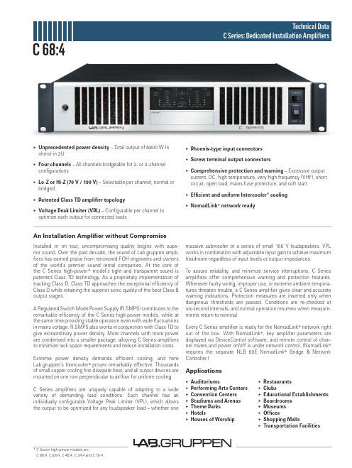
▸▸Unprecedented▸power▸density – Total output of 6800 W (4 ohms) in 2U▸▸Four▸channels▸– All channels bridgeable for 2- or 3-channel configurations▸▸Lo-Z▸or▸Hi-Z▸(70▸V▸/▸100▸V) – Selectable per channel, normal or bridged▸▸Patented▸Class▸TD▸amplifier▸topology▸▸Voltage▸Peak▸Limiter▸(VPL) – Configurable per channel to optimize each output for connected loads▸▸Phoenix-type▸input▸connectors▸▸Screw▸terminal▸output▸connectors▸Comprehensive▸protection▸and▸warning – Excessive output current, DC, high temperature, very high frequency (VHF), short circuit, open load, mains fuse protection, and soft start▸Efficient▸and▸uniform▸Intercooler®▸cooling▸NomadLink®▸network▸readyAn▸Installation▸Amplifier▸without▸CompromiseInstalled or on tour, uncompromising quality begins with supe-rior sound. Over the past decade, the sound of Lab.gruppen ampli- fiers has earned praise from renowned FOH engineers and owners of the world’s premier sound rental companies. At the core of the C Series high-power* model’s tight and transparent sound is patented Class TD technology. As a proprietary implementation of tracking Class D, Class TD approaches the exceptional efficiency of Class D while retaining the superior sonic quality of the best Class B output stages.A Regulated Switch Mode Power Supply (R.SMPS) contributes to the remarkable efficiency of the C Series high-power models, while at the same time providing stable operation even with wide fluctuations in mains voltage. R.SMPS also works in conjunction with Class TD to give extraordinary power density. More channels with more power are condensed into a smaller package, allowing C Series amplifiers to minimize rack space requirements and reduce installation costs. Extreme power density demands efficient cooling, and here Lab.gruppen’s Intercooler® proves remarkably effective. Thousands of small copper cooling fins dissipate heat, and all output devices are mounted on one row perpendicular to airflow for uniform cooling.C Series amplifiers are uniquely capable of adapting to a wide variety of demanding load conditions. Each channel has an individually configurable Voltage Peak Limiter (VPL), which allows the output to be optimized for any loudspeaker load – whether one massive subwoofer or a series of small 100 V loudspeakers. VPL works in combination with adjustable input gain to achieve maximum headroom regardless of input levels or output impedances.To assure reliability, and minimize service interruptions, C Series amplifiers offer comprehensive warning and protection features. Whenever faulty wiring, improper use, or extreme ambient tempera-tures threaten trouble, a C Series amplifier gives clear and accurate warning indications. Protection measures are inserted only when dangerous thresholds are passed. Conditions are re-checked at six-second intervals, and normal operation resumes when measure-ments return to nominal.Every C Series amplifier is ready for the NomadLink® network right out of the box. With NomadLink®, key amplifier parameters are displayed via DeviceControl software, and remote control of chan-nel mutes and power on/off is under network control. (NomadLink®requires the separate NLB 60E NomadLink®Bridge & Network Controller.)▸▸Auditoriums▸▸Performing▸Arts▸Centers▸▸Convention▸Centers▸▸Stadiums▸and▸Arenas▸▸Theme▸Parks▸▸Hotels▸▸Houses▸of▸Worship▸▸Restaurants▸▸Clubs▸▸Educational▸Establishments▸▸Boardrooms▸▸Museums▸▸Offices▸▸Shopping▸Malls▸▸Transportation▸Facilities Applications* C Series high-power models are:C 88:4, C 68:4, C 48:4, C 24:4 and C 16:4 C 68:4L a b .g r u p p e n a b ▸ S w e d e ni n t e r n a t i o n a L c o n t a c t ▸ i n f o @L a b g r u p p e n .c o m | u S & c a n a d a c o n t a c t ▸ i n f o @t c g -a m e r i c a S .c o mw w w .l a b g r u p p e n .c o mSpecifications C 68:4Item no. TDS-C684_V5GeneralNumber of channels4Peak total output all channels driven 6800 W Peak output voltage per channel 141 VMax. output current per channel 24.5 Arms Max.▸Output▸Power 16▸ohms 8▸ohms 4▸ohms 2▸ohms Hi-ZPer ch. (all ch.’s driven)650 W 1200 W 1700 W 1200 W 1600 W (70 Vrms / 100 V peak)Bridged per ch.2400 W3400 W2400 Wn.r.3200 W (140 Vrms / 200 V peak)Performance▸with▸Gain:▸35▸dB▸and▸VPL:▸100▸V THD 20 Hz - 20 kHz for 1 W<0.1%THD at 1 kHz and 1 dB below clipping <0.05%Signal To Noise Ratio>112 dBA Channel separation (Crosstalk) at 1 kHz>70 dBFrequency response (1 W into 8 ohms) +0/-3 dB 6.8 Hz - 34 kHz Input impedance20 kOhm Input Common Mode Rejection, CMR 50 dB Output impedance @ 100 Hz30 mOhmVoltage▸Peak▸Limiter▸(VPL),▸max.▸peak▸output VPL, selectable per ch. 3)141, 118, 100, 85, 71, 59, 50, 42 VVPL, when bridged 3) 1)282, 236, 200, 170, 142, 118, 100, 84 V Voltage Peak Limiter mode (per ch.)Hard / SoftGain▸and▸LevelAmplifier gain selectable (all channels) 1) – rear-panel switches 23, 26, 29, 32, 35, 38, 41, 44 dBDefault gain35 dBLevel adjustment (per ch.)Front-panel potentiometer, 21 position detented from -inf to 0 dB, hidden behind security panel/dust filter grilleConnectors▸and▸switches Input connectors (per ch.)3-pin Phoenix, electronically balanced Output connectors (per ch.)Barrier strip 2-pole screw terminalsOutput bridge mode A+B and/or C+D, inputs A and C are input source NomadLink ® network On board, 2 x RJ45 connectorsIntelligent fans (on/off)Y es, depending on presence of output signal Power on/off and Remote enable on/off Individual switches on front-panelCoolingTwo fans, front-to-rear airflow, temperature controlled speedFront-panel▸indicators Common NomadLink ® Network; Power Average Limiter (PAL) 2); Power onPer channelSignal present / High-impedance; -10 dB and -4 dB output signal; Voltage Peak Limiter (VPL); Current Peak Limiter (CPL); Very High Frequency (VHF); High Temperature; Fault; MutePowerOperating voltage, 230 V / 115 V nominal 130 -265 / 65-135 V 4)Minimum power-up voltage, 230 V / 115 V 171 V / 85 V Power Average Limiter (PAL) 2)YesSoft start / Inrush Current Draw Yes / max. 5 AMains connector 230 V CE: 16 A, CEE7; 115 V ETL: 30 A Twist Lock Dimensions▸(W/H/D)W: 483 mm (19”), H: 88 mm (2 U), D: 343 mm (13.5”)Weight 12 kg (26.4 lbs.)FinishBlack painted steel chassis with gray painted steel front ApprovalsCE, ANSI/UL 60065 (ETL), CSA C22.2 NO. 60065, FCCNote▸1): Automatic -6 dB gain compensation when bridging channels. Ch.’s A+B and/or C+D, can be bridged individually.▸Note▸2): PAL can reduce the maximum output power to keep the power supply operating safely, and/or to prevent excessive current draw tripping the mains breaker. Refer to Operation Manual.▸Note▸3): For sine waves, peak voltage output values translate to Vrms with the formula V/1.41 = Vrms. E.g. 100 V peak equals app. 70 Vrms.Hence, outputs can be set for high-impedance loads without requiring a transformer.▸Note▸4): Separate 230 V or 115 V versions available. Not selectable on the amplifier.▸All▸specifications▸are▸subject▸to▸change▸without▸notice.。
功放的说明书
说明书一、面板布置:1、本功放由功放、播放器、电平指示器、扬声器四个模块组成。
其中功放有放大音频信号的功能,可把播放器音频、外接音频、话筒音频信号放大,通过调节旋钮可改变信号的大小。
播放器有读取内存卡里的音频文件并转化成音频信号(另有收音机功能)的功能。
电平指示模块是通过计算音频信号,获取音频里音调的高低信号,再通过led灯显示出来,具有装饰的功能。
扬声器是把音频信号转化成声音信号的作用。
2、正前方:电平指示 1314⑥⑦⑧⑨⑩ 11 12①②③④⑤左声道右声道①电源指示灯、②音频输入、③音量旋钮、④话筒音量旋钮、⑤话筒输入、⑥播放器电源开关、⑦上一曲/音量-、⑧播放/暂停、⑨下一曲/音量+、⑩播放模式、11数据线插孔、12 usb插孔、13播放器显示屏、14 sd卡插孔(注:11、12、14插孔都是输入插孔,不能输出)3、正后方:变压器变压器线散热器遥控器电源线耳机插孔扬声器插头注意:1、使用前检查电源线和变压器线是否完好,外层绝缘皮是否有破损,若有破损则需要用电胶布粘住,防止皮肤接触而触电。
2、通电时最好不要触碰变压器和变压线。
3、使用时禁止触碰散热器、变压器,防止因温度过高而烫伤。
4、当使用耳机听音频时,只需把耳机插入耳机插孔,但要注意,在使用耳机之前要控制好音量,防止音量过大而损坏耳机。
一般操作是先把音量调为最小,插入耳机后再慢慢增大。
二、使用步骤:1、打开电源:在打开电源前先把音乐音量,话筒音量④调为最小,并确定自带播放器开关⑥处于关闭状态。
然后把电源线接电,则电源指示灯会亮①。
2、接音频:音频有两种,一种是外接音频输入②,另外一种是自带播放器输入,其优先级是外接音频输入高于自带播放器音频输入。
(1)外接音频输入需用一根3.5mm音频线与外界播放器连接,另外一端必须接到功放的外接“音频输入”②插孔,注意播放器的音量③应适当,否则将会烧坏功放芯片和损坏喇叭。
(2)自带播放器输入:首先把优盘或sd卡插入相应位置11、12、13,然后把播放器开关打开⑥,启动自带播放器。
MPA系列专业功率放大器 新板说明书
目录注意事项 (1)产品声明 (2)包装附件 (2)简 介 (3)功能特点 (3)适用范围 (4)面板功能 (5)背板功能 (7)操作说明 (8)开启及关闭设备 (9)技术参数 (10)技术服务 (12)非常感谢您对亿欣电器的关注。
我们为能给您提供一台优质的产品而倍感欣慰。
现在恳请您能在使用本产品前先仔细阅读本手册。
为安全起见,在对本机作各种连接时,请不要抓住线缆进行拉扯,而应握住插头进行操作。
本机仅可在海拔2000米以下环境中使用!请勿对本机做任何线路改动或维修,否则将丧失产品保修权利。
请将本机放置在通风良好的环境中使用。
请不要在雷雨天气时使用本机,以免发生雷击损坏。
请不要使用汽油、香蕉水等化学溶剂擦拭本机,应使用柔软干燥的纺织物擦拭。
请确认您当地的电网电压是否符合本机供电电压要求。
本机使用电源 :交流 220V-230V 50/60Hz请不要破伤电源线,以确保使用安全。
若长期不使用本机时,请拔出电源插头。
本机使用单极开关,开关断开时,本机并没有完全与电网断开、 开箱时请清随机附件是否齐备,并及时办理保修手续.本说明书及操作手册版权属西安原创电子科技有限公司所有,受《中华人民共和国著作权法》的保护。
未经西安原创电子科技有限公司书面明确许可,任何单位、个人不得利用手册中的内容开展生产、销售经营活动,也不得以任何目的、以任何形式或手段复制或传播本手册的任何部分。
并损害用户及西安原创电子科技有限公司的利益,否则西安原创电子科技有限公司将依法追究侵权者的法律责任。
对于不是由西安原创电子科技有限公司提供的产品附属设备或软件,西安原创电子科技有限公司不承担任何使用性或可靠性的责任。
本包装内包含以下附件,请开箱后认真清点;产品说明书 1份 保修卡 1份产品合格证 1份西安原创电子科技有限公司作为知名的音视频产品制造商,旗下:亿欣电器秉承专业、专心、诚信、创新的企业精神,努力开发更适合用户所需的优质产品,为国产音响及视频事业的发展贡献力量。
WT2003M06音频模块说明书

WT2003M06音频模块说明书V1.011.概述WT2003M06是一款小巧的新型高品质音频模块,支持WAV、MP3音频解码。
采用SOP16封装的主控,体积更小,但响应速度更快。
模块采用TF卡作为存储介质,具有USB接口,可以通过PC机自由更换TF卡内的音频内容,并具有USB声卡功能。
并且内置1瓦功放,可以直接驱动1W的喇叭,使用更方便。
2.产品特性支持WAV、MP3高品质音频格式,声音优美。
最大支持32G TF卡,海量存储器。
采用FAT和FAT32文件系统。
PC机可通过USB接口自由更换TF内的音频内容。
支持USB声卡功能。
同时支持按键控制和一线串口通讯,功能更强,控制更灵活方便。
可放置多达65487段音频,海量存储。
内置1W功放,直接驱动8欧姆/1W喇叭,声音洪亮,16级可调音量。
DC 5V供电。
3.技术规格4.模块管脚图5.音频文件排序和掉电记忆功能5.1.音频文件排序WT2003的音频文件按照文件索引排序,是以音频文件先后存放到TF卡的顺序排序,并非按照文件名排列顺序。
因此WT2003播放音频文件的顺序与文件名无关。
由于windows系统中的文件排序,大部分情况都是按照文件名排列顺序,因此我们建议,以采取序号加原文件名的方式命名,如0001歌唱祖国.mp3,0002春天的故事.mp3等。
这样方便windows系统排序。
可以在先电脑上命名好所有音频文件后,排列好顺序,然后整体复制到TF的根目录。
有两种常用的复制方法:一、是用快捷键“Ctrl+C”和“Ctrl+V”,但注意鼠标不能点击到任何选中待发送的文件,否则会以鼠标所点击的文件开始发送的。
这样就会打乱了文件的顺序了。
二、是排列好文件的顺序,选中所要发送的文件,然后右键点击第一个文件(例如0001歌唱祖国.mp3),在右键菜单中选择发送到TF卡的根目录。
(注意右键点击的是要发送的第一个文件,系统会从此文件开始发送的)。
6.控制模式WT2003M06具有两种控制模式:按键控制模式和一线串口通讯。
- 1、下载文档前请自行甄别文档内容的完整性,平台不提供额外的编辑、内容补充、找答案等附加服务。
- 2、"仅部分预览"的文档,不可在线预览部分如存在完整性等问题,可反馈申请退款(可完整预览的文档不适用该条件!)。
- 3、如文档侵犯您的权益,请联系客服反馈,我们会尽快为您处理(人工客服工作时间:9:00-18:30)。
PAM06
Min
Typ
±Vs∓ 8.8 ±Vs∓ 6.6
±Vs∓ 6.8 ±Vs∓ 4
2.5
10
10
4
Max 10
Units
V V µs V/µs nF Ω A
5.5 电源
Parameter Voltage Current, quiescent, boost supply Current, quiescent, total
深圳市优测科技有限公司
8.补偿
Cc 和 Rc 为外部补偿器件,根据所选择增益的大小,选择合适的电容和电阻值。
Gain 1 ≥3
≥10
Cc 470pF 220pF 100pF
9.机械尺寸
Rc 100Ω Short Short
6
Test Condition Full temp range
PAM06
Min
Typ
Max
±15
±75 ±100
22
26
Units
V mA mA
5.6 温度
Parameter
Test Conditons
Resistance, AC, junction to case Resistance, DC, junction to case Resistance, junction to air Temperature range, case
23 24 25 26 29 30 其余
名称 +VB GND CC RC +VS OUT -VS -CL +CL IQ -VB +IN -IN NC
描述 升压电源正极。如果未使用,则它将导通至+Vs。 地,将 2 和 28 这两个引脚连接到系统信号地。 补偿电容连接。根据相位补偿选择值。 补偿电阻连接。根据相位补偿选择值。 电源正极 输出引脚,将这些引脚连接到负载再连接的反馈电阻上 电源负极 连接到限流电阻负载侧。当 RCL 两端的电压增加时,电流限制将激活。 连接到限流电阻的 OUT 侧。当 RCL 两端的电压增加时,电流限制将激活。 静态电流还原引脚,连接到 6 引脚使 AB 产生电压差。 升压电源负极。如果未使用,则短至-Vs。 正相输入 反相输入 不连接
Voltage swing Voltage swing Setting time To 0.1% Slew rate Capacitive load Resistance Current, continuous
Io=10A ±VB=±Vs±10V,Io=10A Av=+1,10V step,RL=4Ω Av=-10,Cc=100pF Full temp range,Av=+1
深圳市优测科技有限公司
功率放大器模块
PAM06
0
深圳市优测科技有限公司
1.概述
PAM06 是一种低成本高性能的功率运算放大器,可在许多工业应用中提供经济高效的解决方案。PAM06 最 高可承受±100V 的供电电压,具有 40KHz 的功率带宽和 125W 的功率耗散能力,同时 PAM06 提供四线制电流 检测和外部补偿功能,用户可根据需求来选择限流电阻和外部补偿的大小。
Full temp range F>60Hz Full temp range F 60Hz Full temp range Meets full range specs
Min -40
PAM06 Typ
12
Max 0.9 1.2
+85
Units
℃/W ℃/W ℃/W
℃
4
深圳市优测科技有限公司
86
98
10
Max 10 50
200 50
Units
mV μV/℃ μV/V μV/W
pA pA/V
pA Ω pF V dB µVrms
3
深圳市优测科技有限公司
5.3 增益
Parameter Open loop,@15Hz Gain bandwidth product Power bandwidth Phase margin
6.安全工作区域
PAM06 的 MOSFET 输出不受 BJT 的二次击穿考虑的限制。但是,安全工作区域需要考虑温度因素和电流处理能力。
7.电流限制
PAM06 可以接成输出电流保护模式,如图 4 连接,两个限流检测线-CL、+CL 分别接在电阻的低电位和高电位端,
不可接反。限流值可按如下方式计算。
5
Test Condition Min
Full temp range, Cc=100pF 94 Io=10A RL=20Ω,Vo=180Vp-p, Cc=100pF Full temp range
PAM06
Typ
Max
113
2
40
60
Units dB
kHz
°
5.4 输出
Parameter
Test Condition
Symbol +Vs to -Vs
VB Io PD VIN(Diff) Vcm
TJ
Tc
Min
-20 -VB
-40 -40
Max 200 +VS±20 25 125 +20 +VB 200 175 +105 +85
Units V V A W V V ℃ ℃ ℃ ℃
5.2 输入
Parameter
Offset voltage, initial Offset voltage vs temperature Offset voltage vs supply Offset voltage vs power Bias current, initial Bias current vs Supply Offset current, initial Input impedance, DC Input capacitance Common mode voltage range Common mode rejection, DC Input noise
2.应用范围
喷墨打印机头的驱动器 压电换能器的驱动器 工业仪器仪表 电机驱动 磁场激励 可编程电源 工业音响
3.典型外部连接
1
深圳市优测科技有限公司
4.外部引脚及描述
引脚编号 1
2,28 4 6
12,13,14 15,16,17 18,19,20
2
深圳市优测科技有限公司
5.规格
注意
测试条件:一般的测试条件为 Tc=25℃,Rc=100Ω , Cc=470pF。
5.1 最大容许电气值
Parameter Supply voltage, total Boost Voltage Output Current, within SOA Power Dissipation, internal Input Voltage, differential Input Voltage, common mode Temperature, pin solder, 10s max. Temperature, junction Temperature storage Operating Temperature Range, case
Test Conditions Full temp range Full temp range
Full temp range Full temp range VCM=±20V 100kHz BW,Rs=1kΩ
PAM06
Min Typ
5
30
15
30
10
0.01
10
1010
20
±VB∓15 ±VB∓12