24V25W双声道功放模块使用说明V01
双路音频放大器产品说明书

Stereo Power Amplifiers Models: PLA300, PLA500 & PLA900Safety InformationThe lightning bolt within a triangle is intended to alert the user to the presence of un insulated dangerous voltage levels within the product’s enclosure. This voltage may be of sufficient magnitude to constitute an electric shock risk. To reduce the risk of electricshock, do not remove coverof this device. There are nouser serviceable partsinside. Refer servicing onlyto qualified servicepersonnel.The exclamation pointwithin a triangle isintended to alert theuser to importantoperating andmaintenance(servicing)instructions in theliteratureaccompanying theappliance.Safety Precautions• Read and retain these instructions• Follow all instructions and heed warnings• Do not use this device near water• If the surface becomes dirty, clean only with dry cloth, do not use solvents or thinners• Install in accordance with the manufacturer’s instructions• Do not block ventilation openings• Do not install near heat sources such as radiators, heat registers, stoves, or other devices that produce heat• Do not defeat the safety purpose of the grounded plug. This plug has twoblades and a third ground prong. The wide blade or third prong are provided for your safety. If the provided plug does not fit into your outlet, consult anelectrician for replacement of the obsolete outlet• Protect the power cord from being stressed at the plugs, conveniencereceptacles, and where they exit the amplifier• Only use accessories specified by the manufacturer• Unplug the device during lightning storms or when unused for an extended time• Refer all servicing to qualified personnel• This device must not be exposed to water in any way. No object filled withliquids should be placed on apparatusCongratulations on your purchase of thisPulse PLA Series Stereo Power AmplifierThis amplifier was designed specifically for use in permanent audio installations or mobile sound reinforcement scenarios, where high reliability and premium sound quality are a must. Highly rugged construction and high efficiency design make this amplifier perfect for continuous duty applications in situations were power will be left on for indefinite periods of time.This amplifier is warranted from defects for one year from the date of purchase. Should your amplifier require service, either within or beyond that warranty period, please contact your Pulse **************************************************.uk.This unit includes a host of features, along with an impressive list of specifications, which are detailed over the next pages. Please take the time to read this document completely prior to installation of this product. Should you have questions regarding installation or operation of this unit, please contact the Pulse Technical Support Department.Features∙240W, 460W & 760W versions∙Class AB amplifiers∙Detented rotary volume controls∙Signal, clip, protect & power LED indicators∙LED VU meter for signal level monitoring∙Delayed switch on to help prevent speaker/amplifier damage∙Over temperature and neutral DC protection∙Rugged steel enclosures with front 19” rack mount ears∙Signal Inputs: 2x 6.35mm (1/4”) unbalanced jack sockets∙Speaker Outputs: 2x Locking speaker socketsSpecificationsApplications∙Live Music, DJ or Installation∙Ideal for powering large speaker cabinets or multiple cabinets in high level sound reinforcement∙This product is designed for professional or commercial use only and is not designed to be used in a domestic environment.Connections / Controls1)Channel 2 speaker output via locking speaker socket. (Use terminals 1+1-only, minimum speaker impedance 4Ω)2)Signal input for Channel 2, via unbalanced 6.35mm (1/4”) jack.3)Air ventilation port – DO NOT BLOCK.4)Channel 1 speaker output via locking speaker socket. (Use terminals 1+1-for Channel 1, and terminals 2+2- for Channel 2, minimum speakerimpedance 4Ω per channel)5)Signal input for Channel 1, via unbalanced 6.35mm (1/4”) jack.6)IEC Mains Inlet – Use only the supplied power cord or suitablereplacement with the correct fuse rating.7)Mains Voltage Switch – This product features a dual voltage power supply.For use within Europe this must be set to the 220-240Vac position.Incorrect selection of mains voltage input will cause the amplifier to failand will not be covered by the standard warranty.Operation:∙All connections to the amplifier should be made while the power is turned off and the attenuators/volume controls are set to the “0” or minimum position.∙As with all amplifiers the connected devices should be powered on in the correct order. When powering up, the amplifier should be the last to beswitched on, when powering down, please ensure the amplifier is switched off first.∙The Pulse PLA series features Signal Clip LED’s to indicate when the amplifier is within 3dB of “clipping”. This indicates the amplifier is receiving itsmaximum input signal and the gain at source should now be reduced.∙Clipped signals are harmful to speakers and amplifiers, they will also sound “distorted” to the ear. Care should be taken to avoid clipping the signal at any point during the signal flow.∙The amplifier features a PROTECT mode indicated by the LED on the front panel. Should the amplifier enter PROTECT mode at any point please switchoff the amplifier immediately. Once powered down the input signal should be turned down to the minimum and the load (speakers) disconnected. At thisstage the speakers and output cabling should be checked for faults/damageand if they are in good working order may be reconnected. The amplifier canthen be powered up again and the input signal increased. Should the amplifier remain in PROTECT mode permanently this indicates a fault and the amplifier will require servicing or repair by an engineer.∙The input connectors on the Pulse PLA series are standard 2-pole unbalanced6.35mm (1/4”) jack sockets.∙Choose speaker cables carefully – please use cables with cores of minimum1.5mm2 and under 10m in length to prevent power loss.∙Check all cables (speaker, signal and mains) for damage, loose terminals or potential short circuits on regular occasions.∙Speaker wires carry high voltages; care should be taken to ensure no bare wires can be touched as this may result in electric shock.∙The Pulse PLA Series features a dual use locking speaker connector on OutputA – this allows both amplifier channels to be accessed using one standardlocking speaker connector. Pins 1+1- are connected to Channel A, pins 2+2- are connected to Channel B.∙Do not use these amplifiers in damp or high humidity environments. Do not use outdoors or anywhere where liquids could fall or splash onto the amplifier. ∙Ensure the amp is adequately ventilated, with free airflow around the front and rear panels. Keep away from other heat sources. If the amps aremounted in a rack with other amps, ensure there is adequate cool air flowfront and rear. Note that air is drawn in through the front panel, andexhausted through the rear panel.∙NEVER cover the amplifiers, as they may overheat.∙PULSE power amplifiers are designed to fit standard 19” racks, with a 2U height and 14.5” depth (not including space for connectors & cables)∙Ensure that the AC power supply is correct for your amplifier. The required AC supply is stated on the rear panel next to the AC power input.∙Ensure that you use the correct type of mains lead for your equipment and country. This must be free from damage and easily accessible during use.∙Keep away from magnetic recording media (tape, mini disc, hard drive etc).Power amplifiers produce an electromagnetic field, which could affect stored files.∙Sound reinforcement systems can produce levels of sound that have the potential to damage a person’s hearing. Please operate this equipment with due care and diligence. If you are in any doubt of the correct operatingvolume for any speaker/amplifier system, please seek advice from a audio industry professional of suitable qualification to advise on Sound Levels. We also advise the use of good quality decibel meters to ensure sound levels are maintained. In the UK the Health & Safety Executive will be able to offeradvise regarding Noise in the Workplace.ComplianceWhen this product reaches the end of its life, do not dispose with household waste. Please dispose of PULSE products in an environmentally sound fashion, or contact PULSE directly via WarrantyPulse products are warranted, by Pulse, against manufacturer defects for a period of one year from the original date of purchase. This warranty is limited to manufacturer defects, in either materials or workmanship. Pulse, or any other worldwide divisions of Premier Farnell PLC, are not responsible for any consequential or inconsequential damage to any other component, structure or the cost of installation or removal of said items.This warranty will not cover damage due to improper use such as (and not limited to) damaged cones, mounting frames, voice coils or items damaged by weather or moisture ingress/exposure.For questions or specific information regarding warranty replacement or repair, contact:PULSE。
DMX24操作指南
1-2
V
V
MAIN, SUB Groups 1-4,
Aux Sends 1-8
V
V
V
MAIN
V
MAIN, SUB Groups 1-4,
Aux Sends 1-8
MAIN, SUB Groups 1-4,
Aux Sends
Talk back
V
2.2.1 杂讯门(Gate)
1-8
MAIN, SUB Groups 1-4,
V
Aux In1&2
Tape In/Bluetooth
V
V
V
V
V
V
V
V
V
V
V
极性 (Polarity)
V
V
V V
音场 (Pan)
V
延迟 (Delay)
V
连接 (Link)
V
输出配送
(Output Assignmen
t)
MAIN, SUB Groups 1-4, Aux Sends
1-8, Internal Aux Sends
Aux Sends 1-8
杂讯门对触发电平以下的信号进行衰减.
9 杂讯门按键(Gate)
通过此按键可控制所选信道是否具有噪音门限功能。该按键 背景灯亮指示此键已按下在工作中。LCD显示实时显示设 定。 参数可通过旋转P1~ P3旋扭直接调节,或是使用上, 下,左,右键选定欲修改之功能再旋转Adjust旋扭调整参数 值。杂讯门启用后其参数值才可调整。
FM910 24V电源模块使用说明书B01

硬件产品用户手册北京和利时系统工程股份有限公司6/25/2007FM91024V 电源模块FM910 24V电源模块目录1.基本说明 (2)1.1 简介 (2)1.2 组成 (2)1.3 特点 (2)2.原理说明 (2)3.使用说明 (2)3.1状态指示灯说明 (2)3.2冗余配置说明 (2)3.3 接线说明 (2)3.4安装和固定 (2)3.5 维护 (2)4.技术指标 (2)HollySys电源模块FM91024V电源模块1.基本说明1.1 简介FM910电源模块是一种开关电源, 实现220VAC到24VDC的转换, 与专用机笼配合使用(如FM300,以下说明均以FM300为例),为现场控制站提供24VDC。
既可以独立使用,也可以冗余使用。
1.2 组成如图1-1所示,FM910为盒式插件结构。
前面板上有状态指示灯、开关按钮、面板紧固螺钉、面板把手;后面板的64针插头插在FM300内的64针插座上,实现与FM300的连接。
将开关按钮按到“ON”状态时,状态指示灯点亮(绿色),FM910加电工作。
1HollySys 11.3 特点FM910模块输出可以并联冗余使用,并具有均流特性。
FM910具有报警输出功能,采用晶体管输出方式,查询电压支持24VDC和48VDC 。
FM910采用铝制外壳,具有较好的散热性能和机械防护能力。
2.原理说明如图2-1所示,FM910实现从交流220V到直流24V的转换,输入级采用浪涌抑制保护,输出级采用过流保护。
3.使用说明3.1状态指示灯说明模块加电时,面板上的状态指示灯(ON灯)显示当前的工作状态。
指示灯亮表示24VDC 输出正常;指示灯灭或异常,表示电源输出为零或电源输出异常。
2 HollySys3.2接线端子定义FM910的接线端子位于机笼FM300的背板上,其端子定义和接线说明详见《FM300机笼单元用户手册》3.3 冗余配置说明FM910可以1:1均流冗余并联使用,共同输出24VDC为系统供电。
24V电源设计工具用户指南说明书

A great deal of detail work is demanded if you want to dimension your 24 V power supply to optimum effect: For all the automation components supplied, you must not only determine the rated current, for example, but also take the inrush current into account. This means, for example, time-consuming searches by hand through catalogs or data sheets. To meet precisely this demand, it has now been made possible to design a power supply unit in the Totally Integrated Automation (TIA) selection tool. This means that, in just a few steps and clicks, you quickly find your way to the suitable power supply for your needs.The profit is in the detailThe increasing level of industrial automation demands not only efficiency, but also a reliable 24 V supply to automation components during operation and in the event of a fault. The solution is the use of a reliable power supply. Meanwhile, there is also the painstaking manual task of collecting and logically processing figures. Here too, the level of complexity soon pushes users to their limits. This is because an optimally dimensioned power supply on the one hand offers you the security that itreliably delivers sufficient current under all operating conditions and, on the other hand, is not over-dimensioned, which would have a negative impact in terms of price and space requirements in the control cabinet. The TIA Selection Tool is designed to help you get things right when selecting a power supply, even at the planning stage. The TIA Selection Tool not only enables suitableThe right choice for a sustainable supplyPower Supplypage 1/4devices to be selected for Totally Integrated Automation, but also configures them so that they are ready to be ordered easily through the Siemens Industry Mall.In comparison with conventional tools, this tool not only manages to combine the configuration of different automation products, but can achieve far more benefits for the user.Convenient selection via the device family viewSelection of the "device family" in the TIA Selection Tool provides a choice of different automation components such as controllers, I/O systems, HMI devices, industrial PCs, drive systems, switchgear, software, communication components, power supply units, and industrial identification systems. In addition, a Profibus and Profinet network can be selected on the basis of associated cables and connectors. (Fig. 1). Under the "power supply" heading, all 24 V power supply units of the Sitop compact, LOGO!Power, Sitop lite, Sitop smart and Sitop modular product lines are listed. The UPS1600 uninterruptible power supply can also be selected by means of the TIA Selection Tool. When selecting this, additional parameters such as load current, buffer time or ambient temperature can be defined. The user has the further option of selecting the Siplus versions and the PSU8600 power supply system (Fig. 2). In addition, a matching power supply in the Simatic design can be implemented in the respective product catalog of the controller.Fig. 1: Simple selection of a power supply using thedevice family viewFig. 2: Possible configuration of the intelligent PSU8600 power supply systemAfter choosing the appropriate automation components, you are automatically guided to the selection wizard. It is also possible for a product to be selected on the basis of technical features via a hardware catalog. In addition, this view offers a comparison component, so that with a simple click several power supply product lines can be compared directly with one another. For expansion of the selected power supply, it is also possible to select a matching redundancy and/or selectivity module (Fig. 3). These can be added by simply clicking on the accessory for the selected power supply. From this product selection in the catalog, the TIA Selection Tool defines a complete list of orders. The list of orders can then be transferred directly to the shopping cart in the Siemens Industry Mall and the product list can be exported in various formats, for example Excel. In addition, you can also request relevant CAX data via the CAX Download Manager.page 2/4page 3/4Fig. 3: Selection of accessories such as a selectivity module for a power supply is possible at any timeNew intelligent 24 V load view in the TIA Selection ToolAlthough you can determine power supply units for automation applications with comparatively few parameters, users have sometimes asked: "What is the current demand during operation?" or "What is the inrush current?". Until now, it was only possible to determine a demand-compliant power supply for automation components with considerable effort. Users who wanted to determine this demand first required a variety of technical data of the individual components, which usually involved a great deal of effort. This should, however, actually be easier to select and determine; ideally, with a suggestion for an appropriate power supply for the specified or selected 24 V load. The TIA Selection Tool also promises assistance in this area.The easy way to find the right power supplyWith the 24 V load view, the appropriate Sitop power supply unit can already be determined for selected automation products. The power requirement of the 24 V loads is calculated automatically and is taken into consideration as soon as the power supply unit is selected. The overview page of the 24 V load view of the TIA Selection Tool displays the automation components previouslyselected by the user. With one click, any power supply unit that has not yet been specified can quickly be added (Figs. 4 and 5). To this end, an additional screen provides instructions on adding a power supply unit. By simply dragging and dropping, the loads can then be connected with one or more power supply units. In doing so, the tool automatically determines the total of the rated and peak currents. The user, however, is free to decide which loads are to be includedin this circuit.Fig.4: Configuration of automation components with a power supply in the 24 V load viewFig. 5: Configuration of two power supplies that supply different loadsUsing the "Edit" function, the selection wizard for the appropriate power supply unit can be started. Only power supply units that deliver the total power required by the loads to be supplied are available for selection. Further parameters can also be defined. Apart from the input voltage (phase selection) and a specific preferred series of products, it is alsopossible to specify a spare capacity forfurther loads or future expansions as apercentage. Furthermore, thespecification of a rated coincidencefactor takes into consideration the factthat the devices in a plant are never allactivated simultaneously at full power(Fig. 6).Fig. 6: Intuitive selection of technical data such aspower reserve, coincidence factor, input voltage,product line, etc.Lastly, there is the possibility of settingup the power supply on a redundantbasis. On confirmation of thisfunction, the appropriate redundancymodule is offered.Flexibility is an essential componentof planningFurthermore, the tool offers twoversions of the configuration atpresent. On the one hand, the TIASelection Tool can be downloaded andinstalled on Windows computers. Inaddition, there is the option of usingthe Cloud version of the tool. This canbe started directly in the browser ofmobile devices. The use of webbrowsers such as Safari, Chrome andFirefox is recommended for thispurpose. The advantage of projectsstored in the Cloud is that you canwork on them using a tablet when youare traveling or from your PC at home.In order to be able to exploit the fullfunctionality, it is recommended inboth cases that an account be set up inthe Siemens Industry Mall. In this way,after creating a bill of materials orordering list, the user can immediatelyorder the products through theSiemens Industry Mall.。
ICP DAS VP-25W1 自动化面板快速启动指南说明书

Version 1.0.2, July 2009Congratulations on purchasing ViewPAC - the most popular automation panel solution for remote monitoring and control application, to give you all the best features of HMIs and PLCs. This Quick Start Guide will provide information needed to get started with ViewPAC. Please also consult the User Manual for detailed information on the setup and use of ViewPAC.In addition to this guide, the package includes the following items:•VP-25W1 Quick Start GuideVP-25W1 & Touch Pen1 GB Micro SD CardScrew DriverRJ-45 Waterproofing Kit Software Utility CDPanel Clips *5The input range of power supply is +10 ~ +30 V DCMake sure the rotary switch placed in the “0” position.Connect the positive terminal (+) of the power supply to the terminal PWR and the negative terminal (-) of the power supply to the P .GND.Connect the USB keyboard to the USB port.2--------------------------------------------------Setting up the power supplyand Connect the mouseOnly high profile I-8K andI-87K modules can be plugged. When you turn on your ViewPAC, it will automatically be on the Windows CE Welcome screen, i t’s almost as operational as Windows XP.4 --------------------------------------------------Powering the View PAC5-----------------------------------------------------------------------------Start the ViewPAC Quick Test to check out the View PAC particular functionsView PAC combines Win PAC, graphic display and keypad dial in one unit. The ViewPAC Quick Test is a toolkit used to check out the View PAC particular function compared with Win PAC.Audio Options:Play Audio button is used to check the audio output.Buzzer Options:LED Options: used to check LEDs sign.to check the KeyPAD.The slider is used to check the LCD backlight.6-----------------------------------------------------------------------------Start the ViewPAC Utility to manage the controllerThe ViewPAC Utility is a toolkit used to quickly control and manage the View PAC.Step 1: Run the ViewPAC Utility located on desktopStep 2: Configure IP addressStep 3: Save and Rebootthe View PAC7----------------------------------------------------------------------------- Start the DCON Utility to configure I-87K series modulesDCON Utility is a tool kit used to quickly control and manage I-87K series expansion I/O modules.Step 1: Run the DCON firmware on the View PAC controllerThe DCON firmware is located at:\System_Disk\tools\DCON_CE\Step 2: Run the DCON Utility on the host PCStep 3: Click the WIN CE buttonStep 4: On the WINCE device connection, enter the IP address of the ViewPAC to search the I-87K series expansion I/O modulesStep 5: It will display a list of I-87Kseries expansion I/O modules, then select the8-----------------------------------------------------------------------------Recalibrate the touch screenThe touch screen has function with the default calibration. It is necessary to calibrate your screen when it works not precise.Step 1: Run the Stylus in the Control PanelStep 2: Tap the touch pen in the exact center of each of the calibrationmarkers ( + )reboot the View PAC⌝ VP-25W1 User ManualCD:\NAPDOS\vp-2000_ce50\Document\/pub/cd/winpac/napdos/vp-2000_ce50/document/⌝ VP-25W1 Demo Reference CD:\NAPDOS\vp-2000_ce50\Demo\/pub/cd/winpac/napdos/vp-2000_ce50/demo/⌝ View PAC Website/products/PAC/viewpac/introduction.htm⌝ ICP DAS Website/技術支援。
SM913 240W24V电源模块使用说明书

图 3 模块端子定义图示
安装
SM913 电源模块采用平面螺钉安装方式,在电源模块的背面有一块带有安装孔的铝板,用来固定 模块。外观尺寸如图 4 所示。
2
HOLLiA MACS
SM913
图 4 外观尺寸图
在平板上按照模块尺寸打好安装孔,如图 5 所示: 1. 将 M4 螺钉拧入平板,注意不要全部拧入,基本固定即可。 2. 将模块的上安装孔套入螺钉,此时下安装孔应该和平板的安装孔刚好重合,用 M4 螺钉定。 3. 将上安装孔的螺钉完全拧入。
SM913 采用模块化设计,整体结构为铝质材料,抗震抗干扰能力强,平面螺钉固定。
图 1 SM913 模块外观图
SM 二级电源解决方案说明:SM913 与 SM941 搭配使用,SM913 试制无问题后将改为量产,即时 SM911-A(明伟产,支持 93.5-242VAC 的宽电压输入)将由量产改为限产,只在 FM 系统及国外 110V 项目 SM 系统配电中搭配 SM941 使用。SM941 量产后,SM940 将停产。
冗余方式
冷却方式
绝缘特性
隔离 耐压
输入与外壳 输出与外壳 输入与输出
绝缘 阻抗
输入与外壳 输出与外壳 输入与输出
LED 指示灯
DC OK
工作环境
工作温度
存储温度
相对湿度
物理特性
外观尺寸(W*H*D)
安装方式
SM913
SM913
176~264VAC 47~63Hz.
满负载 0.96/230VAC 1.4A/230VAC
SM913 模块的硬件工作原理框图如图 2 所示。
图 2 SM913 工作原理框图
使用说明
状态指示灯说明
功放的用法与使用注意事项

功放的用法与使用注意事项功放是音响系统中最基本的设备,它的任务是把来自信号源的微弱电信号进行放大以驱动扬声器发出声音。
功放的使用也需要注意一些事项。
以下是由店铺整理的功放的用法的内容,希望大家喜欢!功放的用法AUdio INPUT是音频信号输入端口,3个都是。
旁边的3个是5、1声道的音源输入端口,平时听、唱歌接AUdio INput这3组中的一组就可以了,5、1声道立体声效果好,看电影合适,但要分几组信号输入。
输出是右边的5组接线端柱(SPEAKERS SYSTEM),从左到右分别是右声道、左声道(左右为主声道)、中置、环绕右、环绕左。
可以接5个音箱,红色为正极,接音箱正极,黑色为负极,接音箱负极。
电脑声卡的输出信号线连接功放的AUdio INput,功放的输出端连接音箱。
无线话筒接入无线咪接收器,输出信号接入功放就行了。
如果有个前级效果器就更方便了,可以把声卡信号和无线咪接收器的信号都输入到前级效果器里,效果器输出再接入功放,这样更好,通过效果器调节音质声音会更好。
功放的作用功放的作用就是把来自音源或前级放大器的弱信号放大,推动音箱放声。
一套良好的音响系统功放的作用功不可没。
功放,是各类音响器材中最大的一个家族,其作用主要是将音源器材输入的较微弱信号进行放大后,产生足够大的电流去推动扬声器进行声音的重放。
由于考虑功率、阻抗、失真、动态以及不同的使用范围和控制调节功能,不同的功放在内部的信号处理、线路设计和生产工艺上也各不相同。
功放的保养方法1、用户应将功放放置在干燥、通风的地方,避免在潮湿、高温、油烟化学制剂有腐蚀性的环境中工作。
2、用户应将功放放置在安全、平稳、不易掉落的台面或机柜中使用,以免碰损或跌落在地上,将机器损坏或引起更大的人为灾害,如火灾、触电等。
3、用户应将功放避开电磁干扰严重的环境,如日光灯镇流器老化等放射的电磁干扰将会引起机器CPU程序错乱,导致机器不能正常工作。
4、PCB布线时注意,电源脚与水溏不能太远,太远可加1000--470U放在它脚边。
SM900 24V5.1VDC双路输出隔离电源模块使用说明书
单相/3 线(N、L、PE)
≥76%
≤0.80A
40A
220 VAC 输入,70 % 负载下,断电后输出不低于 95%额定电压,维持 20ms
自然冷却
<800ms/<90ms(24.5VDC should firstly be setup; 5.1V should firstly be fall) 输出峰值电压<额定电压±5%
输入电压范围
输入频率范围
功率因数校正
漏电流
相数/线数
转换效率
输入电流
冲击电流
维持时间
(hold up time)
冷却方式
Setup Time
Time/Rise
1+1 并联/均流冗余
(current balanced
redundancy)
输出过流保护
输出过压保护
电源故障状态输出
24.5VDC
5.1VDC
亮
亮
正常运行
灭
灭
未上电或模块坏
接线说明
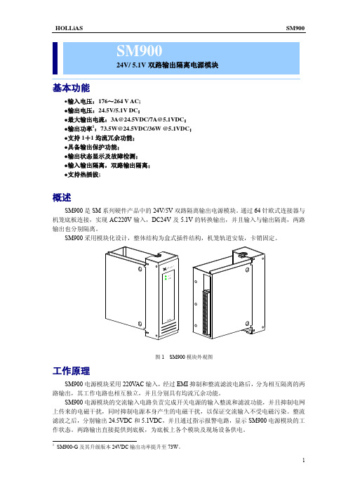
SM900 电源模块应用于 SM 系列 10 槽机笼的电源模块槽位上,如图 4 所示,输入 220VAC, 输出 24VDC/5.1VDC,为机笼中的 IO 模块供电。
图 4 模块安装槽位示意图
SM900 电源模块的 220VAC 从 SM 机笼的交流电源输入端子引入,如图 5 所示。
图 1 SM900 模块外观图
工作原理
SM900 电源模块采用 220VAC 输入,经过 EMI 抑制和整流滤波电路后,分为相互隔离的两 路输出,其工作电路也相互独立,并且分别具有均流冗余功能。
SM900 电源模块的交流输入电路负责完成开关电源的输入整流和滤波功能,并且抑制电网 上传来的电磁干扰,同时抑制电源本身产生的电磁干扰,以保证交流输入不受电磁污染。整流 滤波之后,分别输出 24.5VDC 和 5.1VDC,并且通过指示报警电路,显示 SM900 电源模块的工 作状态。两路输出直接提供到底板,为底板上各个模块及现场设备供电。
- 1、下载文档前请自行甄别文档内容的完整性,平台不提供额外的编辑、内容补充、找答案等附加服务。
- 2、"仅部分预览"的文档,不可在线预览部分如存在完整性等问题,可反馈申请退款(可完整预览的文档不适用该条件!)。
- 3、如文档侵犯您的权益,请联系客服反馈,我们会尽快为您处理(人工客服工作时间:9:00-18:30)。
BMA24225功放模块使用说明
一、BMA24225功放模块概述
BMA 系列功放模块采用进口D 类IC 设计,效率高,体积小,发热小,工作可靠。
BMA 系列功放模块内置短路保护、过热保护、限流保护等,保护功能完善,可靠性高。
BMA 系列功放模块体积小巧,适用于对体积要求严格的场合。
二、BMA24225功放模块原理图和管脚说明
序号标称功能说明
备注
1、40NC 空脚,悬空不接17、18GND 电源输入地
19、20VDD 电源输入正极,12V-24V 21、22SPKR 右声道喇叭输出23、24GND 喇叭公共地25、26SPKL 右声道喇叭输出29、31LCH 、RCH 左右声道输入30
GND
左右声道输入公共地
三、功放模块封装图和尺寸说明(单位:mil
)
四、功放模块电气参数表。