中天智能车库门开门机安装使用手册
汽车车库门电动开关器安装与使用说明书

S M A N U As of date of manufacture, meets all ANSI/UL 325 Safety Requirements for Vehicular Garage Door OpenersM A N U A L C A R E F U L L Y B E F O R E I N S T A L A T I O N O R INSTALLER: Place this manual in the plastic envelope provided andpermanently attach to the wall near the pushbutton.Product Features....................................................2 Tools Required/Component Identification.....2 & 3 Assembly Instructions...........................................3 Identify Your Door Type.........................................4 Important Installation Instructions........................5 Installing the Opener..............................................6 Mounting the Front Bracket............................6 Mounting the Power Head...............................7 Using the Manual Release Mechanism...........7 Installation......................................8 Requirements/Permanent Wiring........9 Control and Auxiliary Equipment........................10 Standard Wall Push Button Installation.......10 Installation of the Super Station...................10 Remote Control Radio System .....................11 TABLE OF CONTENTSOR DEATH. Gives instructions to avoid FCC and IC Radio Operation Statement ......12 Installation of Safe Finish Photosystem.......13 Installation Checklist.....................................14 Operation and Adjustment Instructions............15 Important Safety Instructions.......................15 Basic Operating Parameters.........................15 Testing the Limit Settings.............................16 Testing the Sensitivity...................................16 Testing the Reversing System......................16 Testing the Safe Finish Photosystem...........17 Operating the Super Station Wall Station Wiring Diagram.....................................................18 Auxiliary Equipment Wiring Diagram..................19 Troubleshooting Guide........................................19 Warranty Statement. (20)CAUTION READ THESE STATEMENTS CAREFULLY AND FOLLOW THE INSTRUCTIONS CLOSELY The Warning and Caution boxes throughout this manual are there to protect you and your equipment.Pay close attention to these boxes as you follow the manual.WARNING CAUTION Indicates an ELECTRICAL hazard of DAMAGE to the door, door opener, or equipment. Gives instructions to avoid thehazard .Indicates an ELECTRICAL hazard of INJURY OR DEATH. Gives instructions to avoid the hazard . Indicates a MECHANICAL hazard of DAMAGE to the door, door opener, or equipment. Gives instructions to avoid the hazard . Residential Vehicular Garage Door OperatorMODELS: MVP and MVP-SQSTEPLADDER TAPE MEASUREWOOD BLOCKHAMMERHACKSAW TOOLS REQUIRED FOR INSTALLATION1/2” OPEN ENDWRENCHLEVELSCREW DRIVERSMALL SCREW DRIVER (1/8” HEAD)NOTE:Rail/Chain Assembly is packaged separately from the Power Unit. The Inner Trolley half, Front Idler Sprocket, Chain, and Limit Cams are assembled on the Tee Rail at the factory.Follow the steps outlined below to complete assembly prior to installation. Refer to the component identification illustrations on the previous page.STEP 1: Protect the Power Unit cover fromscratching during assembly by placing it on cardboard. Remove the two 5/16"-18 washered nuts and save them for later use. STEP 2: Position the Tee Rail/Chain Assembly box near the Power Unit. Open the box and locate theInstallation Hardware Packet.STEP 3: Locate the Outer Trolley half (packaged 104363ASSEMBLY INSTRUCTIONSDOOR MOUNTINGFRONT IDLERTROLLEY OUTER CHAIN GUARDWALL MOUNTING BRACKETRELEASE ROPE AND KNOBOPENER HARDWAREBAGTEE RAILRUBBER BUMPEROPENER HEAD UNITPHOTOSYSTEM HARDWARERADIO TRANSMITTERCONTROL WIRESPOOLIMPORTANT!IDENTIFY YOUR DOOR TYPE FROM THOSE ILLUSTRATED BELOW ANDFOLLOW INSTRUCTIONS FOR THAT TYPE OF DOORFOR THESE TYPES OF DOORS USE MODEL MVP OR MODEL MVP-SB. USE 7 FT, 8 FT OR 10 FT RAIL (MATCH DOOR HEIGHT)THE MODEL MVP SERIES IN NOT DESIGNED TO OPERATE THESETYPES OF DOORSone 5/16"-18 washered nut (supplied) Tighten the bolt a MAXIMUM of 1.5 turns after the bolt and nut are Recheck the nuts used to secure the TeeRail to the Power Unit, making sure they are tight. the Chain tension, Chain twist, Chain Guard and the position of both the Close Limit Switch and Open Limit Switch Actuators.CHAIN GUARDACTUATORSPROCKETSPROCKET 104366Assembly is now complete and you are ready to begin installation of the opener.CHAINMASTER LINKOUTER NUTINNER NUTMASTER LINKCHAINDOOR TYPE IDENTIFICATIONONE PIECE DOOR NO TRACKJAMB HARDWAREONE PIECE DOOR NO TRACKPIVOT HARDWAREHIGH ARC OF DOOR TRAVELHIGH ARC OF DOOR TRAVELDOORPIVOT104368TRACKTRACKDOORDOOR104367SECTIONAL DOOR CURVED TRACKONE PIECE DOOR HORIZONTAL TRACK JAMB HARDWAREHIGH ARC OF DOOR TRAVELHIGH ARC OF DOOR TRAVELPower Unit on a ladder or other sturdy support.Open the door to the full open position. Allowsection of the door (as shown in the illustration104372Step 8: Connecting the Door Arm to the Door Type 1: Door Mounted BracketVisually align the door arm connecting hole with the middle hole of the door bracket by rotating the tube section in the appropriate direction.Release the trolley (leave door arm attached) with the manual release cord and pull trolley toward the power head unit. Now rotate the door arm tube section two turns counterclockwise (increasing the exposed length of the door rod) to provide a cushion when the door is closed or encounters an obstruction. Align connecting hole in the door arm to middle hole in the door bracket; insert 3/8” diameter bolt and tighten locking nut, allowing for free pivot of the arm. Note: Do not overtighten locking nut as this will cause binding between the door arm and door bracket.Type 2: Strut Mounted BracketVisually align the door arm connecting hole with the connecting pin of the strut by rotating the tube section in the appropriate direction.Release the trolley (leave door arm attached) with the manual release cord and pull trolley toward the power head unit. Now rotate the door arm tube section two turns counter-clockwise (increasing the exposed length of the door rod) to provide a cushion when the door is closed or encounters an obstruction. Align connecting hole in the door arm with the strut mounted connecting bracket. Insert connecting pin through the hole in the door arm. Secure the connecting pin to the strut bracket according to the manufacturer’s instructions. Note: Door Bracket Mount or Strut Mount - If rod bottoms in cushion tube, cut rod to allow for proper function of this assembly. Set the outer trolley to re-engage, see page 7.Alternate StrutConnecting BracketCut to Fit110054-2Openers are subject to vibration during normal operation which may shorten their life spans.Rough Service bulbs, available at most hardware stores, are recommended. Fit Light Diffuser tabs into the panel slots as shown.On most models, theLimit Cams are installed at the factory. If the Limit Cams have not been installed, or it is necessary to move a Limit Cam to a different link, fasten them to the chain as shown at right in the approximate positions as illustrated below. Position theSwitch Actuators as shown below.104380106428FASTENING LIMIT CAM TOCHAINunder “Special Notes” at the While the LED is. The .LED will blink twice to confirm a valid code and Special Notes - Express CodingRepeat the steps listed above as needed or desired for each button. Each button can be programmed to a unique code, however all three buttons may be programmed at one time (Express Coding). To Express Code, select the “+” button in Step 2, then end the code entry in Step 3 with the “+” button (the first 8 entries can be any random code). The code for each button may be changed at any time.However, if the plus button is programmed as described above, it will replace the existing code settings of the zeroStep 1Step 2Step 3used, slide it into the recess provided on the back of the transmitter caseuntil the snaps on the caseHomeLink® is a registered trade mark of Johnson Controls, Inc. This device complies with Part 15 of the FCC Rules and with RSS-210 of Industry Canada. Operation is subject to the following two conditions: (1) This device may not cause harmful interference, and (2) this device must accept anyPRE-POWER ON-INSTALLATION CHECKLISTBefore continuing with the operation andadjustment section, make sure that:1. The front and rear mounts for the opener aresound and secure and the rail is positionedcorrectly above the high arc of the door, and thatthe opener is positioned over the door actioncenterline.2. For sectional door and one piece door withtracks, the position of the door arm (with thedoor closed), is such that it’s connecting point onthe trolley is 5” to 8” behind it’s connectingpoint on the door bracket. The door arm shouldnever be perfectly vertical when the door in inthe closed position.3. The Manual Release Label and cord are secureto the Manual Release Lever. The handle islocated 6 FT above floor level and requires nomore than a 50 pound pull to activate. Thetrolley and the release mechanism are properlylubricated.4. The standard wall push button or the SuperStation (deluxe wall push button station) is insuch a position and of such a height that it canonly be actuated by an adult of average height.The Control Button Warning label isprominently displayed next to the push button orwall station.5. All wiring is correct to codes or better. There isground continuity form the supply. The groundprong on the power cord is intact.6. All ropes have been removed from the door.The door moves freely without binding whenraised or lowered manually. The door iscorrectly balanced and lubricated. All doorhardware is secure and sound. The sensitivityhas been adjusted to minimum force for theapplication.7. The door reverses on obstructions to within 1.5"of the floor. The concrete or other surfacebeneath the closed door provided uniformcontact.8. The plastic envelope for this manual is attachedto the wall near the push button or wall stationand this manual is placed there for owner useand reference.9. On door with extension type counterbalancesprings, restraint cables have been placedthrough the springs.10. There is Ground Fault Interruption (GFI)protection of the power line to the opener or inthe receptacle.11. On doors with adjustable bottom edges, edgeshave been locked after adjustment.TURNING ON POWER TO THE OPENERNOTE: It is now necessary to turn on the power in order to run the opener to test the operation and check the limit settings. Before doing so, ensure that all mounting hardware is installed and has been properly tightened, that all electrical connections are per local code requirements, and that proper wiring practices have been followed. Also, double-check that all ropes have been removed from the door and that the doorway is clear.BASIC OPERATING PARAMETERS Please note the following Operating Parameters which apply to Openers with Auxiliary Entrapment Protection System (Safe Finish™ Photosystem, Installation Instructions on Page 15) and a standard wall push button connected. Please see page 17 for instructions concerning the Super Station Deluxe Wall Push Button operating parameters.IF THE DOOR IS…...FULLY OPEN, then pushing the standard wall Push Button or the radio control will cause the door to begin MOVING DOWNWARD. ...FULLY CLOSED, then pushing the wall Push Button or the radio control will cause the door to begin MOVING UPWARD....MOVING UPWARD, then pushing the wall Push Button will cause the door to STOP. The next push of the wall button will cause the door to begin MOVING DOWNWARD (Alternate Action Operation)....MOVING UPWARD, then pushing the radio control will cause the door to STOP. The next push of the wall button will cause the door to RESUME UPWARD MOVEMENT (Radio Operation). ...MOVING DOWNWARD, then pushing the wall Push Button or the radio control will cause the door to STOP, PAUSE FOR APPROXIMATELY ONE SECOND, AND THEN BEGIN MOVING UPWARD....MOVING DOWNWARD then reaches the down limit, the lamp will blink off for a 1/2 second then turn back on again, remaining on for 4 minutes 30 seconds and will then automatically turn off....MOVING UPWARD then reaches the open limit, the lamp will remain on for 4 minutes 30 seconds and will then automatically turn off.STEP 3: Testing the Sensitivity Force — To test theSensitivity System, start the Opener and grasp the bottom door handle halfway through the door's travel(opening or closing). When testing in the CLOSEdirection, a second person will be needed to maintainpressure on the Push Button IF an Auxiliary EntrapmentProtection Device has not yet been fitted. If a secondperson isunavailable, use astiff cardboard carton placed in the door's downward path to indicate the force the Opener isOPEN FORCEADJUSTMENTCLOSE FORCE ADJUSTMENT104391THE SENSITIVITY SYSTEM REVERSING TESTENSURE THAT THIS IMPORTANT SYSTEMW A R N I N G1 2 3 4 5 6 7 8 9 Plus Button Zero Button Minus ButtonIF DESIRED, RECORD YOUR RADIO TRANSMITTER CODE POSITIONSETTINGS HERESee Page 11 for Radio System programming instructions and FCC/RSS-210 Industry Canada statement. The opener radio system is HomeLink® compatible.Serial #: Date Installed: Your Dealer:This garage door operatorcomplies with all requirements ofANSI/UL Standard 325.P/N 190-111069 Rev. FX1 August 2007Copyright © 2007 Linear LLC。
电动门控制器的安装调试手册
电动门控制器的安装调试手册一、前言电动门控制器是一种广泛应用于自动门系统中的设备,它能够实现对电动门的控制、监控和保护等功能。
本手册将详细介绍电动门控制器的安装和调试步骤,帮助用户正确使用电动门控制器,并确保其正常运行。
二、安装准备1. 确保所需要的电动门控制器和配件齐全,并检查其是否完好无损。
2. 确定安装位置,并确保该位置适合安装电动门控制器。
3. 关闭电源,并确保操作安全。
三、安装步骤1. 安装控制器面板:将控制器面板固定在预定位置上,并使用螺丝固定好。
2. 连接电源线:将电源线连接到控制器,并进行必要的接地处理,确保电气安全。
3. 连接电动门设备:根据电动门设备的接线图,将电动门设备连接到控制器上,并确保连接牢固可靠。
4. 连接其他外部设备(如传感器、遥控器等):根据需要,将其他外部设备连接到控制器上,并进行相应的设置。
5. 检查连接:检查所有连接是否正确,确保无误后进行下一步操作。
四、调试步骤1. 接通电源:将电源线接通,并确保电流稳定。
2. 启动控制器:按下控制器上的启动按钮,并观察控制器面板上的指示灯是否正常亮起。
3. 调整参数设置:根据实际要求,对控制器进行相应的参数设置,包括开门速度、关门力度等。
4. 检查门的运行状态:通过遥控器或其他操作方式,测试门的开关、停止等功能,观察门的运行状态是否正常。
5. 依次测试其他功能:对控制器的其他功能(如反向、门磁感应等)进行测试,确保各功能正常可用。
6. 调试完成:经过以上步骤的检查和测试后,确认控制器的各项功能正常可用,调试工作完成。
五、注意事项1. 本手册中的安装调试步骤仅供参考,请根据实际情况进行调整。
2. 安装和调试过程中需谨慎操作,注意安全。
3. 如遇到问题,请及时咨询专业人士或厂家技术支持。
4. 严禁私自拆解或改动控制器内部零部件,以免损坏设备或导致安全事故。
六、结语通过本安装调试手册,您可以了解电动门控制器的安装和调试方法,帮助您正确使用电动门控制器,确保其正常运行。
开门器用户操作手册

目录介绍 2-7安全标记和信号词 (2)车库门准备 (3)必需的工具 (4)计划准备 (4)纸箱清单 (7)紧固件清单 (7)装配 8-14装配导轨和滑套 (8)将导轨固定到电机单元上 (9)安装导向滑轮 (10)安装链条/钢丝绳 (11)拉紧链条 (14)安装 15-40重要的安装说明 (15)定位头部支架 (15)安装头部支架.........................................21安装墙壁开关. (28)安装灯泡 (29)安装紧急释放绳和手柄 (30)安装电源 (30)安装保护系统 (31)固定门支架 (34)连接门臂到滑套上 (36)调整 41-43力的调整 (41)门位置的调整 (41)安全反转系统测试 (42)操作 44-51重要安全说明 (44)使用开门器 (45)使用墙壁开关 (46)手动开门 (46)开门器的保养 (47)您有问题吗? (49)将导轨安装到头部支架遥控器编程 52上 (23)固定开门器 (24)悬挂开门器 (26)说明安全标记和信号词本车库门开门机只有严格按照本说明书进行安装,使用,检修与检查才安全可靠。
当你在后面看到这些安全标记和信号词时,他们将警告你如果你不遵守这些警告事项将可能导致严重的伤害或死亡,这些可能是由机械或电所致,仔细阅读警告事项。
当你在后面看到这些信号词时,它将警告你如果不遵守这些注意事项可能会破坏车库门和/或开门器,仔细阅读它们。
车库门准备安装开始前:●去掉锁;●去掉任何连接在车库门上的绳索;●完成以下测试来确定门是否已经被调平衡,以及能否正确的开启和关闭:1、让门停在开启一半的位置,松开手,如果门能够被扭簧支撑而停住,说明门已经调试平衡。
2、开启和关闭门,看是否有卡夹现象如果门被卡住,或没有调试平衡,请打电话给专业安装人员。
必需的工具在开门器的装配、安装和调试过程中,需要图示中的手工具计划准备确定门的类型和重量,测量门的面积,看符合以下那种安装条件,可能需要额外的材料,你会发现这些对你安装开门器是很有用的。
系列车库门遥控器使用说明(带图解)
车库门发展到现在主要分为遥控、感应、电动、手动几种,而车库门遥控器[1]即为远程控制车库门启闭的装置。
一般来讲,车库门遥控器通常采用遥控器中的无线电遥控器,而非红外遥控器,因为与家电常用的红外遥控器相比,无线电遥控器拥有以下的优点,无线电遥控器是用无线电波来传送控制信号的,它的特点是无方向性、可以不“面对面”控制、距离远(可达数十米,甚至数公里)、容易受电磁干扰。
在需要远距离穿透或者无方向性控制领域,比如车库门遥控控制、工业控制等等,使用无线电遥控器较易解决。
下面对无线遥控器做一个简单的介绍:无线遥控器(RF Remote Control)是利用无线电信号对远方的各种机构进行控制的遥控设备。
这些信号被远方的接收设备接收后,可以指令或驱动其它各种相应的机械或者电子设备,去完成各种操作,如闭合电路、移动手柄、开动电机,之后再由这些机械进行需要的操作。
作为一种与红外遥控器相补充的遥控器种类,在车库门、电动门、道闸遥控控制,防盗报警器,工业控制以及无线智能家居领域得到了广泛的应用。
常用的无线电遥控系统一般分发射和接收两个部分。
发射部分一般分为两种类型,即遥控器与发射模块,遥控器和遥控模块是对于使用方式来说的,遥控器可以当一个整机来独立使用,对外引出线有接线桩头;而遥控模块在电路中当一个元件来使用,根据其引脚定义进行应用,使用遥控模块的优势在于可以和应用电路天衣无缝的连接、体积小、价格低、物尽其用,但使用者必须真正懂得电路原理,否则还是用遥控器来的方便。
接收部分一般来说也分为两种类型,即超外差与超再生接收方式,超再生解调电路也称超再生检波电路,它实际上是工作在间歇振荡状态下的再生检波电路。
超外差式解调电路与超外差收音机相同,它是设置一本机振荡电路产生振荡信号,与接收到的载频信号混频后,得到中频(一般为465kHz)信号,经中频放大和检波,解调出数据信号。
由于载频频率是固定的,所以其电路要比收音机简单一些。
7702XR电动车库门安装指南
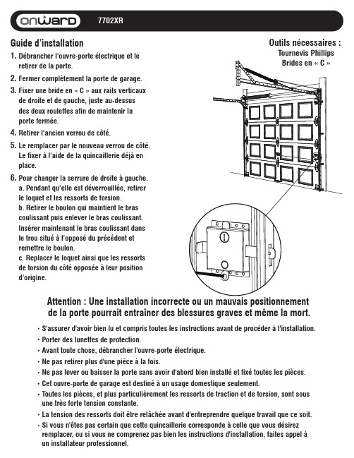
7702XRAttention : Une installation incorrecte ou un mauvais positionnement de la porte pourrait entraîner des blessures graves et même la mort.S'assurer d'avoir bien lu et compris toutes les instructions avant de procéder à l'installation.Porter des lunettes de protection.Avant toute chose, débrancher l'ouvre-porte électrique.Ne pas retirer plus d'une pièce à la fois.Ne pas lever ou baisser la porte sans avoir d'abord bien installé et fixé toutes les pièces.Cet ouvre-porte de garage est destiné à un usage domestique seulement.Toutes les pièces, et plus particulièrement les ressorts de traction et de torsion, sont sous une très forte tension constante.La tension des ressorts doit être relâchée avant d'entreprendre quelque travail que ce soit.Si vous n'êtes pas certain que cette quincaillerie corresponde à celle que vous désirez remplacer, ou si vous ne comprenez pas bien les instructions d'installation, faites appel à un installateur professionnel.Guide d’installation1. Débrancher l’ouvre-porte électrique et leretirer de la porte. 2. Fermer complètement la porte de garage.3. Fixer une bride en « C » aux rails verticauxde droite et de gauche, juste au-dessusdes deux roulettes afin de maintenir laporte fermée.4. Retirer l’ancien verrou de côté.5. Le remplacer par le nouveau verrou de côté.Le fixer à l’aide de la quincaillerie déjà enplace.6. Pour changer la serrure de droite à gauche.a. Pendant qu’elle est déverrouillée, retirerle loquet et les ressorts de torsion.b. Retirer le boulon qui maintient le brascoulissant puis enlever le bras coulissant.Insérer maintenant le bras coulissant dansle trou situé à l’opposé du précédent etremettre le boulon.c. Replacer le loquet ainsi que les ressortsde torsion du côté opposée à leur positiond’origine.Outils nécessaires : Tournevis Phillips Brides en « C »。
superlifts26车库门说明书
superlifts26车库门说明书摘要:1.引言2.superlifts26 车库门的安装步骤a.准备工作b.安装轨道c.安装门板d.安装支撑结构e.安装电子设备3.superlifts26 车库门的操作方法a.遥控器操作b.墙面按钮操作c.手机应用程序操作4.superlifts26 车库门的维护与保养a.日常清洁b.润滑部件c.故障排查与处理5.结束语正文:superlifts26 车库门说明书superlifts26 车库门是一款集安全、美观、实用为一体的车库门产品。
为了帮助您更好地使用这款产品,我们为您提供了详细的安装与操作指南,以及维护与保养建议。
1.引言superlifts26 车库门采用先进的智能控制系统,带给您便捷的车辆进出体验。
本说明书将为您介绍superlifts26 车库门的安装、操作及维护方法,帮助您充分发挥其性能优势。
2.superlifts26 车库门的安装步骤superlifts26 车库门的安装需要一定的专业知识和操作技能。
在安装前,请确保您已阅读本说明书并具备相关经验。
以下是superlifts26 车库门的安装步骤:a.准备工作:检查车库门安装位置的尺寸,确保符合superlifts26 车库门的要求。
清理安装区域,确保地面平整、无杂物。
b.安装轨道:将轨道按照设计要求固定在地面上,确保轨道水平且间距一致。
c.安装门板:将门板与轨道连接,调整门板位置,确保其与轨道紧密贴合。
d.安装支撑结构:在门板顶部安装支撑结构,保证门板的稳定性和安全性。
e.安装电子设备:将遥控器、墙面按钮和手机应用程序所需电子设备安装在指定位置,确保电线连接正确。
3.superlifts26 车库门的操作方法superlifts26 车库门配备了多种操作方式,方便您随时随地控制门的开关。
以下是superlifts26 车库门的操作方法:a.遥控器操作:按下遥控器上的按钮,遥控器将向车库门发送信号,实现开/关门操作。
库门D1000车库门机安装及调试说明
中文中文D1000车库门电机目 录关于安装和维护的通用安全介绍 P2工具和材料 P2CE认证声明 P3对安装者的警示 P31 外型尺寸 P42 技术参数 P43 辅助电子设备 P44 系统图示 P55 预先检查 P56 安装 P66.1 滑动导轨 P66.2 后部固定器 P66.3 外部释放器(可选) P77 安装 P77.1 滑动导轨 P77.2 门上固定 P87.3 控制器 P97.4 释放自动系统 P97.5 外部释放 P98 E1000控制板 P108.1 技术参数 P108.2 E1000控制板元件列表 P108.3 接口端 P108.4 DS1编程拨动开关 P108.5操作逻辑模式 P109 迎接灯 P1110 接口端 P1111编程 P1211.1 电控板设置 P1211.2 学习 P1211.3 预闪 P1312 无线遥控编码的存储 P1412.1 存储DS无线遥控代码 P1412.2 存储SLH无线遥控代码 P1412.3 存储LC无线遥控代码(仅用于部分市场) P1412.3.1 遥控存储LC无线遥控代码 P1512.4 遥控器删除步骤 P1513 开始 P1514 延长电线 P1515 维护 P1516 维修 P1517 附件 P1617.1 中央支架 P1617.2 用钥匙的释放装置 P1617.3 安全充气边缘CN60E P1617.4 电池组件 P16•关于安装和维护的通用安全介绍 工具和材料重要!挤撞危险。
在你开始安装前仔细地阅读完整的安装手册。
不要作任何本手册未提到的改动。
对于一个安全实用的自动门,需要正确地遵守安装步骤和使用说明。
不正确地安装和使用会引起严重的人员和财产不要将本控制器安装用于所指定的以外的用途。
为了紧固,使用所提供的附件或者,无论如何,紧固系统(螺丝,膨胀螺栓,等等)适合于固定的种类和自动系统的机械紧固件。
检查装配门是否符合EN12604 和EN12605 标准(相关信息可以从门本身的文件中找到)。
车库门开门机安装 说明书

其接线方式视开门机机头是否有水晶头插孔而不同。 1)开门机机头无水晶头插孔 接线时打开机头上盖,在线路板找到标有“PB”字样的接线端 子,如下图所示:
标注说明:
+24
为电源接线
GND 为地线
PB 为红外线信号端
PBSW 为墙壁开关信号端
如图所示两线制红外线接法:
PB 接 白线
GND 接 红线
如图所示五线制红外线接法: +24 接 棕线 GND 接 蓝线 PB 接 白线
三、 附件安装 3.1 墙壁开关、光电开关、蓄电池、门磁、报警、外置接收盒、门中 门功能简介
墙壁开关安装在室内,主要功用为控制门体启闭。墙壁开关必 须安装在可看到门体运行情况的地方,并应离地 1.3m 以上,以防止 儿童误操作。
光电开关是一种通过在门洞两侧提供一束不可见光来实现非接 触性安全保护的系统,即当门体在关门过程中如果通道上有人或其他 障碍物阻断光束,门体应立即停下来,然后在两秒钟内反方向运行, 并返回到全开的位置,从而达到安全保护目的。
线路板上留有外置接收盒接口。在自动车库门使用一段时间后, 周围环境会发生变化及自身老化,外界干扰会影响到车库门的遥控距 离。此时可以用外置接收盒来改善遥控效果,解决此类问题。
线路板上留有门中门接口。当门体较大时,在门体下部通常都 有一个小门,便于出入。为安全起见留有此功能,当小门开启时,开 门机处于断电状态,以防止其他人误操作,防止有人出入时出现事故。 3.2 墙壁开关、光电开关接线方法