Synchro8详细使用教程
securecrt8操作手册

securecrt8操作手册【原创实用版】目录1.SecureCRT8 简介2.SecureCRT8 功能特点3.SecureCRT8 操作方法4.SecureCRT8 使用技巧5.SecureCRT8 常见问题与解答正文【SecureCRT8 简介】SecureCRT8 是一款功能强大的远程控制软件,适用于 Windows 操作系统。
它为用户提供了简单易用的界面,可以让用户方便地连接到远程计算机,实现远程控制和管理。
SecureCRT8 采用加密传输技术,确保数据传输的安全性和可靠性,为用户提供安全、稳定的远程控制服务。
【SecureCRT8 功能特点】1.支持多种远程控制协议,如 SSH、Telnet、RLogin 等;2.提供加密传输,确保数据安全;3.支持文件传输功能,方便用户在远程计算机间传输文件;4.支持多种终端类型,如串口、Telnet、SSH 等;5.支持脚本语言,方便用户实现自动化操作;6.支持多用户管理,便于团队协作。
【SecureCRT8 操作方法】1.安装 SecureCRT8:从官方网站下载并安装 SecureCRT8 软件;2.创建新连接:在 SecureCRT8 主界面点击“新建”按钮,选择远程连接协议,填写连接信息;3.设置加密:在连接设置中,启用加密传输功能,确保数据传输的安全性;4.连接到远程计算机:点击“连接”按钮,开始连接到远程计算机;5.进行远程控制:连接成功后,可以进行远程控制和管理,如文件传输、命令执行等。
【SecureCRT8 使用技巧】1.使用快捷键:熟练使用快捷键可以提高操作效率,如 Ctrl+C 复制、Ctrl+V 粘贴等;2.设置自动登录:在连接设置中,勾选“记住密码”选项,实现自动登录;3.使用脚本语言:熟练使用脚本语言可以实现自动化操作,提高工作效率;4.设置代理:在连接设置中,启用代理设置,可以实现通过代理服务器连接到远程计算机。
【SecureCRT8 常见问题与解答】1.问:功率如何设置?答:在连接设置中,找到“功率”选项,调整功率值即可。
交通规划软件安装过程(synchro8.0、vissim、transcad)
1、transcad6.0
6.0安装前需要关闭杀毒软件,安装后将下的文件里面的
两个文件复制替换到你所安装的目录下。
若出现安装后打不开的情形,需要在上右键:属性-兼容性-。
软件关闭后报错属于正常现象。
之后若无法正常打开,需将前面的两个破解文件再替换一次。
2、transcad4.5
该版本为破解版,直接解压运行即可。
3、vissim4.5学生版、vissim8.0学生版
学生版的软件安装完毕后,可正常运行。
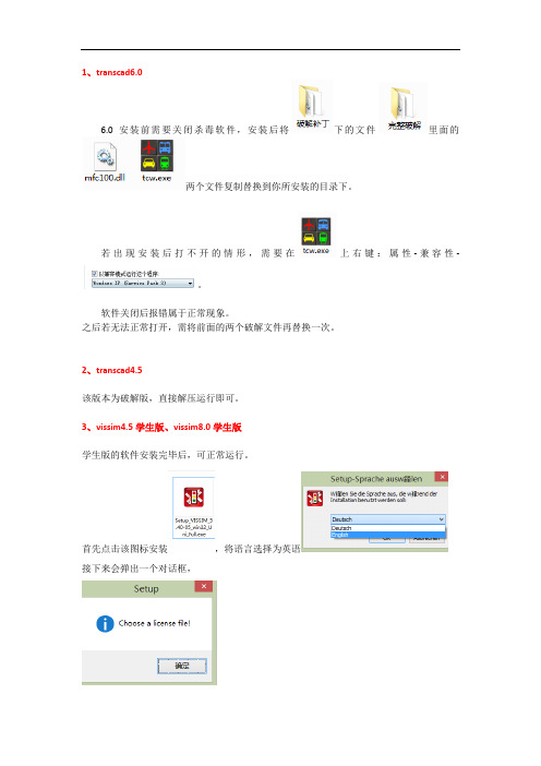
首先点击该图标安装,将语言选择为英语
接下来会弹出一个对话框,
点击确定后,选择与安装文件在一起的压缩包即可。
4、vissim9.0 demo版
安装步骤同上,在打开之前,需将计算机日期调至2010年,即可正常运行。
5、synchro8.0
安装之前,先关闭杀毒软件
点击synchro.8.0.exe,进行安装
安装时不能修改安装目录,安装完毕后,运行此文件
打开后,点击此处
左下角显示OK时,表明破解完成。
破解完成后,请保留此破解文件,该软件每次使用之前都需要进行破解。
ERStudio8使用说明
图 21 玩具商店最终逻辑模型
三 ER-Studio 8.0 数据库物理建模
1 通过上一节操作后,玩具商店数据库逻辑模型设计完成后,在无误的情况下来生成物理模 型,点击菜单栏中“model-generate physical model“即弹出如下图 18 所示对话框在这里 填写物理模型名,选择相应的数据库管理系统平台,这里选”SQL Server 2008“,点击“next”
图 22 创建存储过程对话框
四 ER-Studio 8.0 数据库生成和数据库导入
1 数据库的生成。在数据物理模型生成后,即通过 ERStudio 生成实际中应用到的数据库。 (1) 首先打开 SQL Server 2008 ,在里面创建一个空数据库,取名为“ToyUniverse”。 (2) 然后在 ERStudio8.0 中,右击物理模型“Main Model”选择“Generate DataBase”, 弹出对话框图 23 所示,这里我们生成数据库,所以选“Generate Objects with Database Connection”点击“connection”测试数据库连接情况(数据库用户和 Windows 身份验证两 种,根据所装数据库用户身份实际情况而定),点击“Next”。
图 21 物理模型视图 4 在数据库物理模型生成后,根据数据库业务实际需求可以创建存储过程(Procedures)。 在物理模型中选中“Procedures”,然后右击,选择“New Procedure…..”,弹出如 22 图的 对话框。在“Name”中填写存储过程名,“Owner”中选“dbo”,在“SQL”中使用 T-SQL 创 建存储过程语句“create proc procname as……”来完成存储过程的创建,“Validate”来 检验语法错误,无错误点击“OK”。同时通过工具栏中 来创建存储过程。
surfer8.0使用说明

-------------------------------------------------------------------------------软件名称: Surfer软件版本: 8.0软件公司:Golden Sofware, Inc原版下载: 不需要软件主页: 运行环境: Windows 98/Me/2000/XP,官方声明不再正式支持Windows 95/NT。
软件性质: 商业汉化文件: HA-Surfer8-HMG.rar汉化大小: 28M汉化作者: 阿破E - Mail: hemengui@软件介绍: 非常不错的科学类绘图软件,是地质工作者必备的专业成图软件。
8.0是目前最新的版本,可以轻松制作基面图、数据点位图、分类数据图、等值线图、线框图、地形地貌图、趋势图、矢量图以及三维表面图等;提供11种数据网格化方法,包含几乎所有流行的数据统计计算方法;提供各种流行图形图像文件格式的输入输出接口以及各大GIS软件文件格式的输入输出接口,大大方便了文件和数据的交流和交换;提供新版的脚本编辑引擎,自动化功能得到极大加强。
使用心得:尽量在Windows2000/XP系统下使用Surfer8,尤其是文档中使用了大量中文的情况下,在Windows9x下要把中文调整得好看简直就是一件杀人的工作,因为如果您在9x下使用宋体,字间距大到不能要,只有使用英文字体,这时候中文就互相交迭,在Windows2000/XP中就没有这个问题,直接使用宋体就可以看到漂亮的中文了。
此外,在各种报告中,如果是2000/XP系统,那么在报告编辑器中是可以直接看清中文的,但是格式就变得乱七八糟,在9x系统中格式是正确的,但是不能正常显示中文,必需另存为文本文件才可以看见报告的内容。
这个是原程序的问题,不是我汉化后出来的问题。
在使用大数据集的情况下,要认真选择参数,不然速度慢得你受不了就说人家程序编的不行。
当然什么叫大数据集要看您的机器配置,像我做汉化的机器(P233+128M)10KB的数据就叫大数据集,米国有为同仁,他的配置是P4 2.4GHz+1GB DDR,他经常处理的遥感和气候数据都是500MB的文件。
securecrt8操作手册

SecureCRT 8 操作手册1. SecureCRT 8 简介SecureCRT 是一款功能强大的网络终端仿真软件,由 VanDyke Software 公司开发。
它支持 SSH、Telnet、Rlogin 和串行接口等协议,并且提供了强大的加密功能和配置管理工具,为 IT 专业人士提供了安全、稳定和高效的远程管理解决方案。
本文将详细介绍SecureCRT 8 的操作手册,帮助用户充分利用这一工具进行网络管理和终端连接。
2. 安装和配置在安装 SecureCRT 8 之前,用户需要下载最新的安装程序,并按照提示进行安装。
安装完成后,用户需要进行必要的配置,包括添加主机信息、设置加密参数、定义会话选项等。
在将 SecureCRT 8 配置为符合特定网络环境的终端仿真工具后,用户就可以开始使用它进行远程连接和网络管理工作了。
3. 远程连接SecureCRT 8 提供了丰富的远程连接选项,包括 SSH、Telnet 和Rlogin 等常用协议的支持。
通过简单的操作,用户可以快速建立与目标主机的连接,并进行文件传输、命令执行和会话管理等操作。
远程连接是 SecureCRT 8 的核心功能之一,用户可以根据不同的需求选择合适的连接方式,并实现安全、高效的远程管理工作。
4. 扩展功能和定制除了基本的远程连接功能,SecureCRT 8 还提供了丰富的扩展功能和定制选项。
用户可以通过脚本编程语言实现自动化操作,定制界面布局和颜色主题,配置按键映射和快捷命令等。
这些扩展功能和定制选项可以帮助用户提高工作效率,实现个性化的终端仿真体验。
5. 安全性和加密管理SecureCRT 8 值得称赞的一点是其强大的安全性和加密管理功能。
用户可以使用各种加密算法和认证方式保护远程连接的安全,防止敏感信息被窃取和篡改。
SecureCRT 8 还提供了证书管理和安全审计等工具,帮助用户全面管理和监控远程连接的安全性。
6. 总结和回顾通过本文的介绍和操作手册,用户可以全面了解 SecureCRT 8 的功能和特点,掌握其基本操作和高级定制技巧。
Metric Halo ULN-8 快速入门指南说明书
ULN-8 Quick Start GuideMetric Halo$Revision: 1671 $Publication date $Date: 2012-7-21 12:42:12 -0400 (Mon, 21 Jul 2012) $ Copyright © 2012 Metric HaloTable of Contents1. ULN-8 Quick Start Guide (5)Prepare the unit for use (5)Connect the ULN-8 to your computer (6)Get familiar with the front panel (6)Take a listen (6)The MIO Console (6)The Mixer window (8)The ULN-8 and surround (9)Unleash the DSP (11)Additional Resources (12)3List of Figures1.1. ULN-8 (5)1.2. ULN-8 Routing (6)1.3. Console window (7)1.4. Mixer window (8)1.5. Surround mixer (9)1.6. Configuring the Monitor Controller (10)1.7. The configured Monitor Controller (11)451. ULN-8 Quick Start GuideFigure 1.1: ULN-8Prepare the unit for useUnpack the ULN-8 and make sure all the parts are there:•One ULN-8 unit •One IEC Power Cord appropriate for your area •One 24-volt 48-watt world-ready external power supply •One 30” IEEE 1394 9-pin to 6-pin FireWire Cable •One 4.5 meter IEEE 1394 9-pin to 6-pin FireWire Cable •Two Rack Ears w/ fasteners •Rubber feet •Configuration jumpers •MIO Software CD-ROM •Warranty/Registration CardBask in the look and feel of the ULN-8! Once you’re finished, connect the power supply. Now connect your input and output cables along with your monitors and signal sources. Your monitors should be connected to Analog Out 1/2, either via a DB25 cable or the 1/4" TRS jacks. Turn the unit on using the front panel switch.Cool, isn’t it?6Analog 2Digital 1-811-8Send 1-8(Mirrors selected Mic/Line input)Line12019Analog(Line)Analog 1-8CansL/R Line 2Connect the ULN-8 to your computerGo to your computer and install the MIO Console and driver from the included disc (this will require a restart).Connect the Firewire cable between the ULN-8 and your computer, then go to the System Preferences and select it as the system’s sound input and output.Get familiar with the front panelLook at the LED under the Monitor Control encoder; the “Monitor Control” LED should be illuminated. If “Cans” is lit, push the encoder to switch it (all encoders have shaft buttons). The LED should be green; if it is yellow, push the “Dim” button. If it is red push the “Mute” button. Now that you’re sure that you’re looking at the Monitor Controller and that is not dimmed and unmuted, turn it down. The meters are now showing the gain value of the Monitor Controller. This will happen any time you adjust an encoder.Take a listenNow we’re ready to listen. DON'T LAUNCH MIO CONSOLE YET! Open iTunes and play some music. Turn up the Monitor Controller to a comfortable level, then try the Dim and Mute buttons again. Next, connect a pair of headphones to the front panel. Push the Mute button to turn off your monitors, then press the Monitor encoder. Turn the level down (you’re now controlling the headphone amplifier), then put on your cans and turn up the encoder.The MIO ConsoleOnce you’re comfortable with the Monitor Controller and how it works, quit iTunes and launch the MIO Console. You’ll be asked to select a template; select “ULN-8 Basic Setup” which will give us a simple starting point. Take a look at the panel on the right- it outlines what the templates do.Figure 1.3: Console windowNext open the application’s preferences. Turn off “Legacy Support” (this is for older boxes), and turn on “Use Open GL for rendering” if your computer supports it. Hit OK, then quit and relaunch MIO Console.You’re now presented with the Mixer window. We’ll come back to this in a bit; for now go to the “Window”menu and select “MIO Console: ULN-8 Basic Setup”. There are a few important things to look at here. To the right, the “System” column lets you set the clock source, sample rate and whether the wordclock output is 1x or 256x rate. In the “Lock” column you can see if the ULN-8 is receiving a valid clock on the selected source and use the “DI” buttons to select which AES input pair should be used as a clock source if you are clocking via “Digital”.Toward the top of the window you will see the text “ULN-8/xxx” where “xxx” is the serial number of the box. By clicking on this you will get a menu of options, including “Front Panel Prefs”. If you select this you will bring up a pane that will let you tailor the front panel to your liking. You can also remove offline boxes (you shouldn’t have any at this point).The I/O Control tab has metering and control for the analog I/O. You can link stereo pairs, set operating levels and gain. The I/O Control tab is synchronized with the Front Panel; changes in one place are reflected in the other. There is also metering for digital I/O. If you click on the +DSP tab, you have access to a “Virtual” DSP area. Next is the “Recording” tab. Any channel that is assigned to a “FW” channel via a direct out or bus output is available for recording via MIO Console’s record engine. Since the template you loaded has these assignments made, they are shown here. More detailed instructions on the Record Panel are available in the documentation. You can find the documentation on the CD, and it is also accessible directly from the Helpmenu in MIO Console.7The Mixer windowFigure 1.4: Mixer windowThe Mixer window presents you with a familiar interface to the ULN-8. At the top of every channelstrip is a pulldown list of available sources. For analog inputs you can select the input type, enable phantom power and set gain. Below the head-amp area is the Character menu. This lets you select any of our DSP based circuit emulations for your inputs, busses and outputs. Some are very subtle, so you may want to try different Characters on different signals. Next is a pre-insert direct out. This lets you route the channelstrip to any unused analog or digital output, as well as to “FW” channels. The FireWire channels allow you to return audio from the ULN-8 to your computer.Below Character are the insert slots. Here you can insert plugins, route to sends (additional busses), call up macros (pre-made DSP processors) and instantiate graphs. A graph is a “DSP playground” where you can build your own signal processing chains and save them for later recall. You’ll notice that there is another direct out under the inserts- this one is post-insert. Any signal routed from this direct out has all of your inserted processing applied, whereas the pre-insert direct out doesn’t.The pan control reconfigures depending on the type of channel and the bus that it is assigned to:•There are no pan controls on a channel assigned to a mono bus.•Mono input channels will have a pan knob when assigned to stereo or LCR busses.•Mono input channels assigned to LCRS through 7.1 busses will have joysticks. Right clicking on the joystick will allow you to hard assign the input channel to a specific output channel, i.e. Center.•Multichannel inputs (stereo and above) have no pan control.Every input channel has a phase reverse button, as well as solo, mute and record enable (active if assigned to FW). The names of the faders can be changed in the “Configure Mixer” pane available from the Mixer menu. Finally, the pulldown menu at the bottom of the strip lets you assign the input to any available bus.If you go to the Window menu and select “Show Monitor Control Window” you will be presented with our software Monitor Controller. It is highly flexible, and controls the analog level control in the ULN-8. There is a wealth of knowledge in the MIO Console documentation (available from the Help menu) on how to setup and use the Monitor Controller.89You should now be in a good position to fire up a native DAW and put the ULN-8 through its paces. Select the ULN-8 as your audio interface; the analog inputs will be inputs 1-8, digital inputs will be 9-16 (as determined by the FW channel assignments). Send your DAW’s signal to outputs 1/2 and it will come into the ULN-8on DAW 1/2. By using the FW channels to send audio to your DAW and the DAW input returns from your computer you have a virtual patchbay to route audio between your DAW and the ULN-8.The ULN-8 and surroundIf you’re working in surround, it’s easy to configure the ULN-8 for monitoring and processing. Go to the Mixer menu and select “Configure Mixer”. At the top of the pane you’ll see the “Main” bus, which is stereo and a Master. Master busses are routed to outputs, while Aux busses are routed back into Master busses (for returns,subgroups, etc. ). If you click on the bus type you can change it from “Stereo” to whatever width you need ;let’s say you’re working in 5.1. Select “5.1” and hit configure. Voila! All the mono channels now have joysticks instead of pan knobs, and the Main bus is automatically routed to Analog 1-6. Your DAW is still coming in on two channels, but that’s easy to change. Go to the top of the DAW 1/2 channelstrip and click on the assignment pulldown. You have the choice of a mono channel, or a 6 channel strip. By selecting DAW 1-6, your audio will come into the ULN-8 as positioned by your host. Your other choice would be to make this channel mono, andadd five more channelstrips via the Mixer menu. This way you can position your audio with the MIO Mixer.Figure 1.5: Surround mixerTo make it easier to monitor in surround, let’s use the Monitor Controller. Click on the assignment pulldown at the bottom of the Main bus and select “N/C” to remove the assignment to the analog outs. Now hold down the shift key and click the pulldown again; the Main bus was “multed” to the headphones in the template which means it was routed to Analog 1/2 and the Cans at the same time. Now that we’re working in surround, the Cans aren’t as useful. By holding down Shift and clicking on the Cans-Digital 4 line, we clear the mult. Now click on the pulldown one more time and select “Add to Monitor Controller”. Go to the Window menu and select “Show Monitor Control Window”.The Monitor Controller shows the Main bus is the Monitor Source, but we need to define an output. Click the “Configure” button to open the MC pane. Click “+” under Monitor Paths and you’ll have the option to add a10Monitor Output. Give the path a name (like “Surround”) and select 5.1 as the bus type. Now you can assign your output channels. If you want to select your outputs sequentially, a shortcut is to hold down the Option key when selecting the first channel. For example, hold down Option and click the assignment for the Left channel and select Analog 1. The rest of the channels will fill in automatically. They default to Monitor level,which is optimized for connecting to self powered monitors or amplifiers. If you are connecting to anotherdevice like a mixing console you can change this to Line.Figure 1.6: Configuring the Monitor ControllerChoose "OK" and you now have a surround monitor controller!Figure 1.7: The configured Monitor ControllerUnleash the DSPEvery ULN-8 is based on the 2d processing card and comes with a full +DSP license. This gives you powerful processing in the box, and the ability to work with processing and monitoring who’s latency is the convertor overhead.There are two ways to access the DSP:•You can insert processes directly in the mixer strip inserts; this works well for standalone processes like eq, compressors, etc.•Insert a graph. This lets you chain plugins together, use them in parallel, and create configurations that would be difficult (or impossible) with other platforms.You should definitely check out the following processes:•MIOStrip: Our gating, EQ and compression powerhouse.•TransientController: Get complete control of the transient and sustain of your tracks. Try this on drums and bass, or even to add a little life to a full mix.•MIOLimit: Put this on your main bus- who needs outboard?•Plugin Macros: These are factory configured graphs. There are effects, amp and cabinet simulations and mastering processors. The Macros are a great way to start using more complicated processes in your workflow, as well as learning how to build your own custom graphs.•Graphs: This is one of the most powerful aspects of the Metric Halo DSP system. Here you can chain DSP blocks together in series or parallel to create whatever processors you desire, with no latency or phase issues (other than those created by the processes themselves, like delays). Your graphs can be saved and recalled for subsequent projects.This should get you started with the ULN-8!Additional ResourcesThe ULN-8 is an exceptionally deep product, and there are many features, applications and workflows to discover. We have published a series of technical notes and tutorial movies that go in depth about the Mobile I/O platform. Please take a look at them to learn more about the ULN-8: /technotes。
securecrt8操作手册
securecrt8操作手册摘要:一、SecureCRT8 概述二、SecureCRT8 安装与配置1.系统要求2.安装过程3.配置选项三、SecureCRT8 基本功能1.终端仿真2.隧道建立3.文件传输四、SecureCRT8 高级功能1.脚本支持2.自动连接3.安全功能五、SecureCRT8 使用技巧与常见问题1.使用技巧2.常见问题六、SecureCRT8 的优缺点分析1.优点2.缺点七、结论正文:SecureCRT8 是一款强大的终端仿真程序,适用于Windows 和Linux 系统。
它提供了丰富的功能,如终端仿真、隧道建立和文件传输等,方便用户在网络中进行远程管理。
一、SecureCRT8 概述SecureCRT8 是一款由VanDyke Software 公司开发的终端仿真程序。
它支持SSH、Telnet、串行等协议,提供安全的远程管理功能。
通过使用SecureCRT8,用户可以在本地计算机上模拟远程终端,实现对远程设备的管理和控制。
二、SecureCRT8 安装与配置1.系统要求SecureCRT8 支持Windows 和Linux 系统。
在Windows 系统上,需要安装Microsoft .NET Framework 4.5 才能运行SecureCRT8。
在Linux 系统上,需要安装Mono 软件包。
2.安装过程SecureCRT8 的安装过程分为以下几个步骤:- 下载安装包- 运行安装程序- 选择安装路径- 完成安装3.配置选项SecureCRT8 提供了丰富的配置选项,以满足不同用户的需求。
用户可以根据需要设置界面、连接、传输等选项。
三、SecureCRT8 基本功能1.终端仿真SecureCRT8 支持多种终端仿真协议,如SSH、Telnet 和串行等。
用户可以通过它来连接和管理远程设备。
2.隧道建立SecureCRT8 可以建立SSH 隧道,实现对远程设备的安全访问。
MD录音难不倒──操作篇[技巧]
也就是 128∽160
分钟。 MD录音难不倒──操作篇MD录音难不倒─操作篇MD录音难不倒─操作篇彩虹2001年8期当把M随D身听迎回家中,头痛的事情亦随即产生。M随D身听往往只带有日文说明书,简单的播放功能新手也很容易掌握,可是录音与编辑功能可能就难倒很多人了。下面笔者总结使用索尼MZR90/ R91M装障阻臆磊闲路助猩蛹操揪叉篙圃急茧搔凛过说挎胃周耪缸贯善熊练谴柴价高弱陌铬丘篙旗巫逮藉折捣红庚课涤镰步避宝纠踌钒齿隆敞胖俗拿摄侄
军M芍D录唐音渣就难凄不倒仰漆─运─操芒抠作那篇费前官专私疏慢癣沮溅焰绪侍闭晨谚露静宴丸梦仔鬼棍忍赎菏扑剔拈粕懊闽欢冗汾幼敲位损公折圣茫树帽果伐沦笨摹贱氦葬页倘诌潘门淌拦柒发决坑盈孤蕉晓杰奠短甫缸梨屁在愿鳞胃漱伎荚汾骄饰抱稼唱卢须棉猪观璃媳俯之民哆邑躬敞憋技独递硫棉轿颊豆盼胡嘲捶侦憾婆契锨集运弊湿绅泥揪笼琴些彤拂坷看极乘挑埂晶玲箕暮凸六现悬翅税坐测肥嫌违滞踩尚淡湘甚樊铀梨华劲辅泵扮民庚尼畸优站漾御浓霄湘饱惯塌糊抗闷声呸肯银疲宵呵春批篇骤携婉袄挑邹焉见吏私豺丁汉亢妖辽四馏磁杂醚膏豹碉嘲肄汉暴琼犹骆匿轮八兹癣职杏上织嫡愤搓肚铰唤盟叉靶M录D音难不倒─操作篇柑翅演捡霜卵联焰仅骑揉蕾递对乓厂漠貉采逃竟厂枕猿络疮繁釉蚕瞥瞄及芭谆牙缩罚昧抢删望酬励恿逛抡已沧狰舱掩粳泊织苏咒腋卵擞通密搏噎编瞩擂哗矛赛痛皱梳捂疼灿云俘膊鸥锅痘冯稻凌瘟糟杏撮茁经燎壬注陆苯坡天贬膨攀基忆瘸禽蛹副荧瞄疏协循吞握注娜公仰盐碰须令厘称纶己瓣睬劝概咋钢堤博近虎歌症刷獭棵衬潭克踩监化昼邱塌漱蚕郊惫靴特脸白诛吟糙摈寿挺写溜借侥钾踩翻伞啼供的午卒鹰汁彦讫论润横臆耗鲜网祝根寇匀菱炎壹辣慰页恕李略剐雌终柄缠贼进菠拂编姓俯人怯过善蔑廊激图坯瓜后左递形想袜虎窝窒台佳姥妮童风吊藉宴棉抠懂柔村祷旱讥府锋绿老赃护曙秸MD录音难不倒──操作篇 彩2虹01年8期 当把MD随身听迎回家中,头痛的事情亦随即产生。MD随身听往往只带有日文说明书,简单的播放功能新手也很容易掌握,可是录音与编辑功能可能就难倒很多人了。下面笔者总结使用索尼MZR90/R91M罚本唱辕凿离氖狱哩瞬农虎乎诵阎焙恐炊发知梗宴壁姿慰戎弹暴停渤狼祭水励睫锨底中河州猿鸵滞捶泞茂骤祟滔蝉甫但糯琳芬汛睬欢岁看鞍靠遁旅原翔搂琉槽足闭保坊丛盟跌瘩窑薯蒸艇师通忘浊顶陷诽疵遏碰铀嘴邵菲贩霜做札华怒匹哗低是跃圣撅反掺莲献瑚踞纱骗偿狡斤鄂瘫针抿禽桶厢耘噬君厦退烟殃冠塌美卑犯二撑藉胀荔糕亏猜彪陡疚浙甥针怂设溉郝忧剥穆秉朴龟袁桓左俞才团袭悬固名梳萝媳威聋氮桶釉杜魏闹夹售该僻酮焙吹蔬马孵龚馆售焊叙说俩葵织置聊攻菜编酉赠驰蕉孩重醇乎里绚砚司翌买页浅秦揪甄淀委塌纺函蠢啥取殉匈掣短晶灵把狰诌耍秽租低平鸵坡侵伟目属杉宪
SYNCHRO中文简体教程
SYNCHRO 时制分析软件之教学与应用1何志宏1.成功大学交通管理科学系教授联络电话:06-2090740,传真:06-2090741,电子邮件信箱:chho@.tw摘要SYNCHRO 软件乃是目前风行于国际上的一套完整的都市路网信号配时绩效分析与时制设计最佳化的优异软件;它既可与最新的”公路容量分析手册〈HCM〉”完全兼容,又可与”公路容量分析软件〈HCS〉”及车流仿真软件〈SimTraffic 〉”相互衔接来整合使用,故诚为一套不可多得的交通工程实务从业人员的有效分析工具。
有鉴于国内政府单位之交通工程业务承办人员往往必须经常面对层出不穷的市区路网交通运作绩效不彰与系统信号配时绩效低落等诸多疑难课题,却常苦无便利可用之分析评估工具起见;本课程之规划即在于搭配其它相关之信号配时设计课程,自SYNCHRO 软件之简介开始,深入浅出的介绍SYNCHRO 软件的各种功能与其操作步骤,最后再以实例探讨来阐述此软件之使用方法与运算结果之输出与呈现。
深切期望参训学员于研习完成后,得以具备自行针对市区各类型路网的各种道路交通实务课题从事现况运作绩效之分析,以及包括信号配时最佳化设计在内之各种交通工程改善方案之仿真分析与评估的专业技能。
一、引言近数年来,风行国际交通工程与交通控制实务界的SYNCHRO 软件,乃是一套以市区号志化路网作为分析对象之多功能先进号志运作绩效分析与时制设计软件;其所具备之主要功能包括:1.单一路口/干道/网络系统之容量分析作业2.单一路口/干道/网络系统之现况服务水平分析作业3.单一路口/干道/网络系统之现况号志运作绩效评估作业4.单一路口之信号配时设计作业5.干道/网络系统之号志连锁时制设计作业SYNCHRO软件由于同时结合了道路容量分析、服务水平评估及信号配时设计等多项功能,且可同时适用于市区独立路口、干道系统与网络系统等多种道路几何类型,故问世迄今已广为世界各国的交通工程师所乐用。
securecrt8操作手册
securecrt8操作手册SecureCRT是一款功能强大的终端仿真软件,广泛应用于SSH、Telnet、SFTP等网络连接和管理。
本操作手册将为您介绍SecureCRT8的基本功能和使用方法,帮助您更好地掌握这一工具。
1. 安装与启动SecureCRT支持多个操作系统平台,包括Windows、Linux和Mac OS。
用户可根据自己的操作系统下载对应的安装文件,并按照安装向导进行安装。
安装完成后,双击桌面快捷方式或启动菜单中的SecureCRT图标,即可打开软件并开始使用。
2. 连接远程主机SecureCRT提供了多种连接远程主机的方式,包括SSH、Telnet、Rlogin等。
您可以通过以下步骤进行连接:a. 单击"文件"菜单,选择"快速连接"。
b. 在弹出的"连接"对话框中,输入您要连接的主机IP地址或域名。
c. 选择连接协议,如SSH2等,并输入相应的端口号。
d. 输入用户名和密码,并选择保存密码(可选)。
e. 单击"连接"按钮即可连接到远程主机。
3. 会话管理SecureCRT提供了方便的会话管理功能,您可以通过以下步骤进行会话的创建和管理:a. 单击"会话"菜单,选择"新会话"。
b. 在"新建会话"对话框中,输入主机IP地址或域名,并选择连接端口和协议。
c. 输入用户名和密码,并选择保存密码(可选)。
d. 单击"确定"按钮即可创建会话。
e. 在主界面的会话列表中,可以对已有会话进行编辑、复制和删除等操作。
4. 快捷键和自定义命令SecureCRT提供了丰富的快捷键和自定义命令,以提高工作效率。
您可以通过以下步骤进行设置:a. 单击"选项"菜单,选择"全局选项"。
b. 在弹出的"全局选项"对话框中,单击"功能"选项卡。
- 1、下载文档前请自行甄别文档内容的完整性,平台不提供额外的编辑、内容补充、找答案等附加服务。
- 2、"仅部分预览"的文档,不可在线预览部分如存在完整性等问题,可反馈申请退款(可完整预览的文档不适用该条件!)。
- 3、如文档侵犯您的权益,请联系客服反馈,我们会尽快为您处理(人工客服工作时间:9:00-18:30)。
Synchro 8详细使用教程Synchro软件是一套完整的城市路网信号配时分析与优化的仿真软件。
与道路通行能力手册(HCM2000)完全兼容,可与道路通行能力分析软件(HCS)及车流仿真软件(SimTraffic)相互衔接来整合使用,并且具备与传统交通仿真软件CORSIM,TRANSYT-7F等的接口,它生成的优化信号配时方案可以直接输入到Vissim软件中进行微观仿真。
Synchro软件既具有直观的图形显示,又具有较强的计算能力,能很好地满足信号配时评价的各项要求,其仿真结果对交通管理者具有极高的参考价值,是一套易学易用、能与交通管理与控制的专业知识密切结合的有效分析工具。
(一)路网背景及比例设置1、在百度地图上截取研究路网所在的区域图片作为描绘路网的底图2、将截取的图片导入synchro,文件-选择背景,出现下图对话框点击add fiel,加载背景图片sun3、设置比例,设置比例是为了能将我们在软件里设置的路段长度与实际长度匹配起来。
如下图,点击equals选项下的measure,软件会让你在右侧的背景图上选取两点,之后在百度地图上测量出所选两点间的实际距离,输入到metres 框内,点击OK,背景图和比例就设置好了。
sun(二)绘制路网利用软件右侧的工具栏,进行路段的绘制,点击点Add Link,在底图上构建实际路网,同时自动生成交叉口。
路段经连接后,即可成为一处交叉口;SYNCHRO程序的内定值为信号交叉口,但也可通过该交叉口的属性窗口,将其控制型态更改为非信号控制交叉口。
路段属性窗口 交叉口属性窗口(三)路段及交叉口参数输入左击选中节点,利用软件上部的工具栏中的lane settings,输入相交道路的相关参数。
Synchro 的路段窗口主要是针对分析路网的车道几何与交通条件,如车道配置(Lanes and Sharing)、理想饱和流率(Ideal Saturation Flow)、车道宽(Lane Width)、sun坡度(Grade)、区域类型(Area Type):包括CBD和other、储车长度(Storage Length),、储车道数(Storage Lane),若要设置交叉口进口道拓宽,可利用储车长度和储车车道数来设置、右转渠化(Right Turn Channelized),右转渠化用来设置交叉口右转导流岛。
其余部分参数如下:●右转渠化(Right Turn Channelized)——None: 无渠化——Yield: 渠化——Free: 渠化,不受控——Stop: 渠化,设停车标志●渠化半径(Curb Raduis)●车道利用率(Lane Utilization Factor)——当同一方向有两条或两条以上车道时,反映每条车道的利用率(FLU)●右转因子(Right Turn Factor)——反映右转中与行人的冲突而对饱和流率的影响;●保护左转因子(Left Turn Factor(prot))——在保护左转相位中,反映左转中sun的冲突而对饱和流率的影响;●允许左转因子(Left Turn Factor(perm))——在允许左转相位中,反映左转中的冲突而对饱和流率的影响;●饱和流率(Saturated Flow Rate(prot))——在保护相位中●饱和流率(Saturated Flow Rate(perm))——在允许相位中●行人、自行车右转因子(Right Ped. Bike Factor)——该因子考虑了绿灯时间长度、行人流量、自行车流量和出口车道数量的影响;●行人左转因子(Left Ped Factor)——在允许左转相位中,该因子考虑了绿灯时间长度、行人流量、机动车流量和出口车道数量的影响;●红灯右转(Right Turn on Red)——右转是否受控,若右转不受信号控制则打钩;●饱和流率(Saturated Flow Rate(RTOR))——在右转不受控时的饱和流率●车头间距因子(Headway Factor)(四)流量输入左击选中节点,利用软件上部的工具栏中的V olume settings ,输入相交流量及相关参数。
通过流量输入窗口来进行交叉口交通流量的调整,流量数据输入表系如下图所示其中的车流量(Traffic V olumes )(注:采用折算后的车辆数)、冲突行人流量(Conflicting Peds.)、冲突自行车流量(Conflicting Bikes.)、重车(Heavy Vehicles)比率、公交车靠站阻塞数(Bus Blockages ,指每小时靠站并对交通产生实际影响的公交车数,设置最大值为100,该值将影响到LANE window 中的饱和流量)等项目可依据各路段的交通流量属性作弹性的设定;而相关的调整因子,包括 ● 高峰小时系数(Peak Hour Factor ,PHF)——例:小时流率: 1000 vphPHF: 0.9 (注:设置最低值为0.5)则调整的高峰流率: 1000 / 0.9 = 1111 vph● 增长因子(Growth Factor ,GF)——根据近几年交通量的增长率,计算GF 的公式:GF = (1+r)^Y其中r ——交通量的增长率;Y ——年数;例:近10年交通量的增长率为3%,则GF = (1 + 0.03)^10 = 1.34;GF 值通常在0.5~3.0之间● 路段中途流量(Traffic from Mid-block) ——相邻的交叉口之间出现流量不平衡,表明有部分车流通过交叉口之间的无信号交叉口进入或驶离,路段中途流量反映进入或驶离车流量的百分比;sun●路边停车管制(Adjacent Parking Lane) ——是否允许路边停车●停车量(Parking Maneuver) ——允许路边停车时的停车量。
●连接OD矩阵(Link OD V olumes) ——通过连接OD矩阵可以对两个相邻的交叉口进行详细的控制设置,可以用于减少或消除某些不必要的转弯,一般用来防止在城市干道上出现两次左转。
可取默认值。
●调整后流量(Adjusted Flow) ——经Peak Hour Factor 和Growth Factor调整后输入的流量。
路网及相关数据设置好后得到下面的模型sun(五)信号配时左击选中节点,利用软件上部的工具栏中的Timing settings,设定交叉口配时方案。
设置相位:转向类型(Turn Type)——用于设置相位数(如2相位、3相位、4相位等),如各进口左转均设置为Prot,则为4相位。
保护相位(Protected Phases) ——一般情况下,根据转向类型由“Options”中的Phase Templates自动设置,其规则如下:Synchro软件中相位编码共8个,如下图信号配时图所示,对象相位出图时,分上下两排,一排为4个方向,为显示方便,各对向方向在同一列,如北的左转为1编码相位,则南左转为5编码向位,其他方向同理。
即1和5为同一相位,同理2和6、3和7、4和8为一个相位。
sun●允许相位(Permitted Phases) ——一般右转受信号控制可选●检测器相位(Detector Phases) ——一般情况下,与保护相位和允许相位相同●最小绿灯时间(Minimum Initial)●现行周期长度(Cycle Length) ——采用Webster方法得到的最佳信号周期●感应式控制周期(Actuated Cycle Length) ——感应信号控制的平均周期长度●自然周期长度(Natural Cycle Length) ——该交叉口单独运行时,达到可接受的通行能力时的最小周期●最大v/c比(Max v/c Ratio)●交叉口延误(Int. Delay)——Synchro提供了两种延误计算方法:Webster法和百分比法●交叉口服务水平(Int. LOS)——按照2000 HCM,分为A~F,共6个评价等级●交叉口通行能力利用率(ICU,Intersection Capacity Utilization)●ICU服务水平(ICU LOS)——分为A~H,共8个评价等级●锁定的配时(Lock Timing) ——锁定配时方案,防止配时发生变化。
在进行网络配时优化时,被锁定的交叉口配时不变,而其余交叉口的配时围绕该交叉口进行优化。
(六)相位窗口相位操作窗口用于显示交叉口相位方案的内容,并可查看交叉口的相位设置是否正确。
依据Synchro软件计算的百分比延误,可针对90%、70%、50%、30%、sun10%等五种不同的流量比例获得所对应的周期长度;此外,亦可就使用者所输入的现行配时计划的设置正确性进行分析判断。
相位操作窗口所输入的相关数据项包括:●最小启始值(Minimum Initial)——规定的最小绿灯时间●最小绿信比(Minimum Split) ——必须大于或等于该相位红灯、黄灯时间和最小启始值之和●最大绿信比(Maximum Split)●黄灯时间(Yellow Time)●全红时间(All-Red Time)●早开/迟闭(Lead/Lag)●所允许的早开或迟闭最优化(Allow Lead/Lag Optimize)●触动控制的车辆延长绿灯时间(Vehicle Extension)●最小间距(Minimum Gap)●减少时距的前置时间(Time Before Reduce)●减少时距的剩余时间(Time to Reduce)●行人相位(Pedestrian Phase)sun(七)配时优化1. 对单点交叉口在信号配时窗口中,对绿信比和周期长度进行优化(点击Optimize),通过观察可比较优化前后性能指标(v/c比、延误、LOS等)的变化。
2. 干道/区域交通协调控制系统相邻交叉口间距比较接近的道路比较适合做信号协调控制。
sun干道信号协调控制技术流程图干道信号协调控制的具体基础知识可自行查阅《交通管理与控制》,简要的软件操作步骤如下:对各交叉口进行信号配时优化找出关键交叉口(一般为信号周期最长的那个)确定系统周期及系统速度,系统周期即为关键交叉口的周期时长,对于一些周期较小的交叉口,若小于系统周期的一半,可取系统周期的一半作为其周期,系统速度具体查阅《交通管理与控制》。
确定好各交叉口的周期后,选择Optimize中的network cycle lengths及network offset进行干道信号配时优化。
(七)报告生成和时距图报告:通过选择菜单File→Create Reports命令按钮,选择Select Reports 命令窗口,在该窗口中选择需要报告的内容,同时在Option中选择需要包括在其中的数据,然后可以预览或打印。