新型SmartFusion2SoCFPGA评测工具套件
fpga芯片的种类

fpga芯片的种类FPGA芯片的种类FPGA(Field Programmable Gate Array)是一种可编程逻辑器件,它具有灵活可塑性和高性能,被广泛应用于数字电路设计和嵌入式系统开发领域。
随着技术的不断发展,FPGA芯片也呈现出多样化的种类和功能,本文将介绍几种常见的FPGA芯片。
1. Xilinx Virtex系列Xilinx Virtex系列是业界最强大的FPGA产品系列之一。
它以其卓越的性能和丰富的资源而受到广泛关注。
Virtex系列采用了最新的FPGA架构,具有高达数百万个可编程逻辑单元(LUT)和丰富的高速IO接口,可满足复杂系统设计的需求。
此外,Virtex系列还提供了丰富的硬核IP(Intellectual Property),如处理器核、高速串行收发器等,使其在高性能计算和通信领域具有重要应用。
2. Altera Cyclone系列Altera Cyclone系列是一种低成本、低功耗的FPGA芯片,广泛用于嵌入式系统和消费电子产品中。
Cyclone系列采用了先进的工艺技术,具有较高的逻辑密度和丰富的资源。
该系列芯片在功耗控制上表现出色,可满足对低功耗需求较高的应用场景。
Cyclone系列还支持多种外围接口和通信协议,如CAN、SPI、I2C等,方便与其他设备进行通信和互联。
3. Lattice iCE系列Lattice iCE系列是一种超低功耗的FPGA芯片,适用于移动设备和便携式电子产品。
iCE系列采用了极小的封装和低功耗设计,能够在极端环境下提供可靠的性能。
该系列芯片具有快速启动和低功耗特性,适合应用于电池供电的场景。
iCE系列还具有较高的集成度和资源利用率,可满足对系统复杂度和成本要求较高的应用。
4. Intel Stratix系列Intel Stratix系列是一种高性能、高密度的FPGA芯片,由英特尔(Intel)公司推出。
Stratix系列采用了英特尔的最新工艺技术,具有卓越的性能和可靠性。
将FPGA技术与mcu相结合单芯片解决方案

将FPGA技术与mcu相结合单芯片解决方案嵌△式设计人员花费大量时间为手头的任务寻找合适的微控!避(MCU)O通常,空间是一种约束,原始性能、I/O、内存资源、功耗和外围设备的正确组合成为寻找合适的圣杯。
如果您具有特定设计所需的特殊逻辑,则搜索会变得更加复杂。
也许这是一种“秘方”,您的公司比任何人都知道如何做得更好,并使最终产品脱颖而出。
在这种情况下,很可能没有人按照您想要的方式制造MCU还有另一种选择:协同MCU和FPGA配对。
高度密集的FPGA可以吸收如此多的逻辑,以至于它们可以与微控1避甚至内部微控制器结合,从而比单独使用任何一个部分做得更多。
此外,您的逻辑的专有本质隐藏在FPGA内部,不会被窥探。
本文讨论了允许设计人员将FPGA技术与嵌入式处理器相结合的几个选项。
我们将研究单片方法、片上系统(SOC)解决方案、堆叠和模块。
单甚庄解决方案可以使Micros运行得非常快。
我们都熟悉触手可及的数千兆赫处理避。
然而,更快的处理器通常成本更高且更难实现。
PCB走线变成了传输线,需要严格的阻抗控制,尤其是在关键路径信号上。
并非每个设计都能承担使用此类设备进行开发的成本和时间。
这使得以较低速度运行的成本更低、更通用的处理器成为我们设计的替代、更经济的选择。
对于要求不高的应用,仅此一项就很好,但是当对速度的需求超过了微型的周期时间时,我们就不得不做出选择。
基于软件的方法无法与功能的硬逻辑实现的速度竞争。
您可以在板上使用离散逻辑,或将处理器内核与纯逻辑资源(如FPGA)耦合。
虽然使用更简单、不太复杂的处理器可以相当容易地设置、控制和监视实时控制和状态机设计,但有时需要更高端的外围设备、更宽的数据路径、更高的安全性和更快的执行速度需要。
这种级别的处理器马力的一个很好的例子是MicroSemiSmartFUSiOn2系列部件,例如M2S050T-FGG896,它实际上是基于SoC 的,将硬核IP块和FPGA结合在一个芯片上。
Actel的SmartFusion混合信号FPGA开发评估方.
Actel的SmartFusion混合信号FPGA开发评估方Actel的SmartFusion混合信号FPGA开发评估方案Actel公司的SmartFusion 是集成了FPGA,ARMCortex-M3和可编程模拟的智能混合信号FPGA,非常适合硬件和嵌入系统设计.本文介绍了SmartFusion混合信号FPGA主要特性,方框图,以及SmartFusion评估板主要特性,部分电路图和马达控制与工业自动化的开发方框图.Actel’sSmartFusionIntelligentMixed-Signa lFPGAsaretheonlydevicesthatintegrateanFPGA,ARM®Cortex™-M3,andprogrammableanaloActel的SmartFusi on混合信号FPGA开发评估方案Actel公司的SmartFusion是集成了FPGA, ARM Cortex-M3和可编程模拟的智能混合信号FPGA,非常适合硬件和嵌入系统设计.本文介绍了SmartFusion混合信号FPGA主要特性,方框图, 以及SmartFusion评估板主要特性,部分电路图和马达控制与工业自动化的开发方框图.Actel’s SmartFusion Intelligent Mixed-Signal FPG As are the only devices that integrate an FPGA, ARM® Cortex™-M3, and programmable analog, offering full customization,IP protection, and ease-of-use. Based on Actels proprietary flash process, SmartFusion FPGAs are ide al for hardware and embedded designers who need a true system-on-chip (So C) solution that gives more flexibility than traditional fixed-function microcontrollers—without the excessive cost of soft processor cores on traditional FPGAs.SmartFusion主要特性:Microcontroller Subsystem (MSS)• Hard100 MHz 32-Bit ARM® Cortex™-M3– 1.25 DMIPS/MHz Throughput from Zero Wait State MemoryMemory Protection Unit (MPU)– Single Cycle Multiplication, Hardware Divide– JTAG Debug (4 wires), Serial Wire Debug (SWD, 2 wires), and Single Wire Viewer (SWV) Interfaces• Internal Memory– Embedded Nonvolatile Flash Memory (eNVM), 64 Kbytes to 512Kbytes– Embedded High-Speed SRAM (eSRAM), 16 Kbytes to 64 Kbytes, Implemented in 2 Physical Blocks to Enable Simultaneous Access from 2 Different Masters• Multi-Layer AHB Communications MatrixProvides up to 16 Gbps of On-Chip Memory Bandwidth,1 Allowing Multi-Master Schemes• 10/100Ethernet MAC with RMII Interface2• Programmable External Memory Controller,2 Which Supports:– Asynchronous Memories– NOR Flash, SRAM, PSRAM– Synchronous SRAMs• Two I2C Per ipherals• Two 16550Compatible UARTs• Two SPI Peripherals• Two 32-Bit Timers• 32-Bit Watchdog Timer• 8-Channel DMA Controller to Offload the Cortex-M3 from Data Transactions• Clock Sources– 1.5 MHz to 20 MHz Main Oscillator– Battery-Backed 32 KHz Low-Power Oscillator with Real-Time Counter (RTC)– 100 MHz Embedded RC Oscillator; 1% Accurate– Embedded Analog PLL with 4 Output Phases (0, 90, 180, 270)High-Performance FPGA• Based on Actels proven ProASIC®3 FPGA Fabric• Low-Power, Firm-Error Immune 130-nm, 7-Layer Metal, Flash-Based CMOS Process• Nonvolatile, Live at Power-Up, Retains Program When Powered Off• 350 MHz System Performance• Embedded SRAMs and FIFOsVariable Aspect Ratio 4,608-Bit SRAM Blocks– x1, x2, x4, x9, and x18 Organizations– True Dual-Port SRAM (excluding x18)– Programmable Embedded FIFO Control Logic• Secure ISP with 128-Bit AES via JTAG• FlashLock® to Sec ure FPGA Con ten ts• Five Clock Conditioning Circuits (CC Cs) with up to 2 Integrated Analog PLLs– Phase Shift, Multiply/Divide, and Delay Capabilities– Frequency: Input 1.5–350 MHz, Output 0.75 to 350 MHzProgrammable AnalogAnalog Front-End (AFE)• Up to Three 12-Bit SAR ADCs– 500 Ksps in 12-Bit Mode– 550 Ksps in 10-Bit Mode– 600 Ksps in 8-Bit Mode• Internal 2.56 V Reference or Optional External Reference• One First-Order ΣΔ DAC (sigma-delta) per ADC– 12-Bit 500 Ksps Update Rate• Up to 5 High-Performance Analog Signal Conditioning Blocks (SCB) per Device, Each Including:– Two High-Voltage Bipolar Voltage Monitors (with 4 input ranges from ±2.5 V to–11.5/+14 V) with 1% Accuracy– High Gain Current Monitor, Differential Gain = 50, up to 14 V Common Mode–Temperature Monitor (Resolution = ¼°C in 12-Bit Mode; Accurate from –55℃ to 150℃)• Up to Ten High-Speed Voltage Comparators (tpd= 50 ns)Analog Compute Engine (ACE)• Offloads Cortex-M3–Based MSS from Analog Initialization and Processing of ADC, DAC, and SCBs• Sample Sequence Engine for ADC and DAC Parameter Set-Up• Post-Processing Engine for Functions such as Low-Pass Filtering and Linear Transformation• Easily Configured via GUI in Libero® Integrated Design (IDE) SoftwareI/Os and Operating Voltage• FPGA I/OsLVDS, PCI, PCI-X, up to 24 mA IOH/IOLUp to 350 MHz• MSS I/Os– Schmitt Trigger, up to 6 mA IOH, 8 mA IOL– Up to 180 MHz• Digital VCC = 1.5 V (FPGA and MSS), Analog VCC = 3.3 V and 1.5 VSmartFusion intelligent mixed signal FPGAs are uniquely suited for active motor control for permanent magnet motors, servo motors,series motors, separately excited motors, and alternating current (AC) induction motors.图1.SmartFusion方框图SmartFusion评估板The SmartFusion Evaluation Kit offers a simple, low-cost way to try the worlds only FPGA with hard ARM Cortex-M3 and programmable analog. The SmartFusion device contains on-chip flash and on-chip SRAM memory, and the kit adds additional SPI flash memory, an OLED display, and built in Ethernet connectivity. The evaluation kit board alsoincludes LEDs, switches, and various voltage, current and temperature monitoring functions for analog experimentation on the board.图2.SmartFusion评估板外形图The SmartFusion Evaluation Kit board includes:A2F200M3F-FGG484ES200,000System FPGA gates, 256 KB flash memory, 64 KB SRAM, and additional distributed SRAM in the FPGA fabric and external memory controllerPeripherals include Ethernet, DMAs, I2Cs, UARTs, timers, ADCs, DACs and additional analog resourcesRefer to the SmartFusion product page for full device informationSPI-flash memory connected to SPI_0 on the deviceUSB connection for programming and debug from Actels design toolsUSB to UART connection to UART_0 for HyperTerminal examples10/100 Ethernet interface with on-chip MAC and external PHYRVI header for application programming and debug from either Keil or IAR SystemsMixed-signal header for daughter card supportUser Inputs and OutputsOLED display with I2C interface connected to I2C_0 on the deviceFirst-order ΣΔ DAC (sigma delta) output with 12-bit 500 Ksps update ratePotentiometer used to vary voltage input for voltage and current monitoring8 LEDs connected to the FPGA fabric for FPGA demonstration2 user input switches connected through FPGA fabricBoth LEDs and switches can be used with GPIO by connecting through the fabricSelector to choose between GNU SoftConsole or RVI-Header for debugSelector to switch between programming the device (fabric) and debug modeOn-board 20 MHz crystal for system clockOn-board 32.768 KHz for RTC5 user I/Os for debugOption to use internal 1.5 V regulator图3.SmartFusion评估板的OLED连接图图4.SmartFusion评估板的20MHz和32.768kHz振荡器连接图图5.SmartFusion评估板的USB到UART连接图图6.SmartFusion评估板的以太网接口连接图图7.SmartFusion评估板的低成本编程器连接图图8.SmartFusion评估板的A2F200 JTAG连接图Designing with SmartFusion involves three different types of design: FPGA design, embedded design and analog design. These roles can be filled by three different designers, two designers, or even a single designer, depending on company structure and project complexity. Actel has developed design tools and flows to meet the needs of these three types of designers so they can work together smoothly on a single project.• FPGA Design—Libero® Integrated Design Environment (IDE) isActel’s comprehensive software toolset for designing with all Actel FPGAs. Libero IDE includes industry-leading synthesis, simulation and debug tools from Synopsys® and Mentor Graphics®, as well as innovative timing and power optimization and analysis.• Embedded Design—Actel offers FREE SoftConsole Eclipse-based IDE, which includes the GNU C/C++ compiler and GDB debugger. Actel also offers evaluation versions ofsoftware from Keil and IAR, with full versions available from respective suppliers.• Analog Design—The MSS configurator provides graphicalconfiguration for current, voltage and temperature monitors, sample sequencing setup, and post-processing configuration, as well as DAC output.The MSS configurator creates a bridge between the FPGA and embedded designers so device configuration can be easily shared between multiple developers.图9.采用SmartFusion的设计流程连接图SmartFusion intelligent mixed-signal FPGAs are uniquely suited to active motor control for permanent magnet motors, servo motors, series motors, separately excited motors and alternating currentinduction motors. A SmartFusion FPGA can actively manage multiple electric motors, including start and stop, control of rotational direction, speed and torque, protection against motor overloads or faults and active control using closed loop performance algorithms. SmartFusion on-chip resources allow you to monitor motor performancein real time with or without dedicated encoders, applying corrective control signals to maintain commanded direction, speed and torque and deliver precise motor position control.Actel’s motor control partner, Power and Control Desi gn, Inc., has produced a SmartFusion Motor Control Development Kit that enables demonstration and benchtop development of your world-class permanent magnet motor control products.The kit includes five reference designs with source files:• Trapezoidal u sing Hall effect sensor feedback• Sinusoidal using Hall effect sensor feedback• Sinusoidal with encoder feedback• Sensorless trapezoidal with back-EMF feedback• Ethernet interactive control of motors图10.马达控制开发方框图The range of peripherals SmartFusion offers for the Cortex-M3 processor and the flexibility of its FPGA fabric make the deviceideal for industrial automation. The SmartFusion Development Kit supports Ethernet, EtherCAT, CAN, UART, I2C and SPI hardware, while firmware can be used for various other interface standards such as Modbus® and PROFIBUS for industrial networking. With the use of the programmable analog for sensing and analog outputs, SmartFusion can also be used in industrial control applications, including gateways, sensing, actuators and I/O devices. The list below describes how the various sections of the device could be used in industrial automation.Microcontroller Subsystem• ARM Cortex-M3 running Fieldbus protocol stack• Ethernet MAC – standard protocolsFPGA Fabric• Multiple RS485 capable UARTs- PROFIBUS, Modbus, WorldFIP, P-NET• High Speed Manchester Encoding/Decoding • CANAnalog• ADC for sensing• DAC for excitation图11.工业自动化开发方框图。
美高森美推出用于SmartFusion 2 SoC FPGA的基础原型构建平台的入门者工具套件

美高森美推出用于SmartFusion 2 SoC FPGA的基础原型构建平台的入门者工具套件
美高森美公司(Microsemi),宣布提供SmartFusion 2入门者工具套件,为设计人员提供用于其SmartFusion2系统级芯片(SoC)现场可编程门阵列(FPGA)的基础原型构建平台。
SmartFusion2入门者工具套件支持包括以太网、USB、SPI、I2C和UART 的业界领先接口,并且包含一个通用的电路板,以支持独特的设计要求。
这款工具套件使用Microsemi的Libero SoC v11.0 beta开发软件,其带有免费的Libero Gold授权许可和预烧入的uClinux演示。
通过使用其中的USB WiFi 适配器,这款套件可以支持RaLink 5370 USB无线通信卡,允许uClinux设置一个用于DHCP WiFi连接的无线接入点。
用户可以启用一个HTTP服务器,然后通过智能手机网络浏览器或其它无线设备接入SmartFusion2器件,该器件支持Emcraft Systems的Linux-based 开发环境。
SmartFusion2器件位于Emcraft Systems 微型(34mm x 59mm)板上(M2S-SOM),该板连接至SOM-BSB-EXT基板。
这款工具套件使用USB供电,包括FlashPro4编程和以下用户接口及功能。
• 采用FG896 封装的SmartFusion2 SoC FPGA (M2S050T-FG896ES)。
智能融合2系列SoC FPGA开发板使用指南说明书
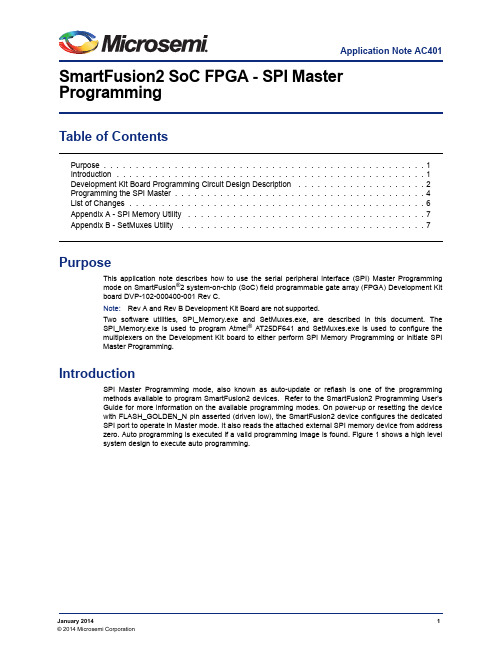
Application Note AC401January 20141© 2014 Microsemi Corporation SmartFusion2 SoC FPGA - SPI Master ProgrammingTable of ContentsPurposeThis application note describes how to use the serial peripheral interface (SPI) Master Programming mode on SmartFusion ®2 system-on-chip (SoC) field programmable gate array (FPGA) Development Kit board DVP-102-000400-001 Rev C.Note:Rev A and Rev B Development Kit Board are not supported.Two software utilities, SPI_Memory.exe and SetMuxes.exe, are described in this document. The SPI_Memory.exe is used to program Atmel ® AT25DF641 and SetMuxes.exe is used to configure the multiplexers on the Development Kit board to either perform SPI Memory Programming or initiate SPI Master Programming.IntroductionSPI Master Programming mode, also known as auto-update or reflash is one of the programming methods available to program SmartFusion2 devices. Refer to the SmartFusion2 Programming User's Guide for more information on the available programming modes. On power-up or resetting the device with FLASH_GOLDEN_N pin asserted (driven low), the SmartFusion2 device configures the dedicated SPI port to operate in Master mode. It also reads the attached external SPI memory device from address zero. Auto programming is executed if a valid programming image is found. Figure 1 shows a high level system design to execute auto programming.Purpose . . . . . . . . . . . . . . . . . . . . . . . . . . . . . . . . . . . . . . . . . . . . . . . . . . 1Introduction . . . . . . . . . . . . . . . . . . . . . . . . . . . . . . . . . . . . . . . . . . . . . . . . 1Development Kit Board Programming Circuit Design Description . . . . . . . . . . . . . . . . . . . . 2Programming the SPI Master . . . . . . . . . . . . . . . . . . . . . . . . . . . . . . . . . . . . . . . 4List of Changes . . . . . . . . . . . . . . . . . . . . . . . . . . . . . . . . . . . . . . . . . . . . . . 6Appendix A - SPI Memory Utility . . . . . . . . . . . . . . . . . . . . . . . . . . . . . . . . . . . . . 7Appendix B - SetMuxes Utility . . . . . . . . . . . . . . . . . . . . . . . . . . . . . . . . . . . . . . 7SmartFusion2 SoC FPGA - SPI Master Programming2Development Kit Board Programming Circuit Design DescriptionThe Development Kit board programming circuitry has an on board FT4232H module from Future Technology Devices International (FTDI). This module is a universal serial bus (USB)-to-serial interface converter. For more information on FT432H module, see FTDI website at /Products/Modules/DevelopmentModules.htm. This module is connected to the M2S dedicated SPI port and the SPI memory device using the multiplexers. The multiplexers can then be configured either manually or through SetMuxes.exe utility described below to program the Atmel SPI memory device or to initiate an auto-programming operation. The Development Kit board is designed in this fashion to program the SPI memory device on board through the FTDI chip. Figure 2 shows how the multiplexers are connected.Figure 1 • Auto Programming (SPI- Master) ModeDevelopment Kit Board Programming Circuit Design Description3Figure 2 • Connection of MultiplexersFigure 3 • Development Kit Board Programming Circuit - Auto Programming ModuleSmartFusion2 SoC FPGA - SPI Master Programming4Note:Some of the FT4232H I/O pins control the enable and select signals of the multiplexers.SetMuxes.exe configures these pins to either perform the SPI memory programming manually or initiate auto-programming.Programming the SPI MasterThe following steps describe how to program the SPI master.1.Set the jumpers on the Development Kit board as:–J43 (Pin 1 - Pin 2)–J55 (Pin 1 - Pin 2)–J70 (Pin 2 - Pin 3)2.Install the FTDI drivers based on the operating system as described in the FTDI driver installationguide available at: /Support/Documents/InstallGuides.htm.3.Copy the following files into a local directory on your PC.–FTCJTAG.dll: Used for interfacing FT2232 to devices using the JTAG protocol.Note:Click the file name to download a ZIP file containing the library.–libMPSSE.dll : This library has been created to aid the implementation of I2C designs using FTDI devices which incorporate the FTDI MPSSE.–SetMuxes.exe: Refer "Appendix B - SetMuxes Utility"for more information.–SPI_Memory.exe: Refer "Appendix A - SPI Memory Utility"for more information.–Click here to download a sample demo project containing both the exe files.4.Copy the programming file (.spi) to a local directory on the PC. Use one of the .spi files included inthis demo package or generate a design and export it through Libero ® System-on-Chip (SoC)software. For more information on how to use Libero software, refer /download/software/liberosoc/default.aspx.5.Open the Command Prompt and navigate to the directory where the files are saved.6.Connect the Development Kit board mini USB (J24) to the PC.7.Power-up the Development Kit board.Figure 4 • Development Kit Board Programming Circuit - FT4232H ModuleProgramming the SPI Master58.In the command prompt, type:SetMuxes MEMThis application sets the multiplexers for the FTDI chip to access the Atmel memory device on the board. Figure 4 shows an example message on successful setting-up of the multiplexers.9.In the command prompt, type:SPI_Memory -aprogram <file name>.spiThis updates the Atmel spi memory device, as shown in Figure 6.10.In the command prompt type the following:SetMuxes REFFigure 5 • SetMuxes MEMFigure 6 • aprogram <file name>.spiSmartFusion2 SoC FPGA - SPI Master Programming6This command sets the multiplexers for the M2S chip to access the Atmel memory device on the board and initiates reflash, as shown in Figure 7. The M2S device functions with a delay of approximately a minute. The functioning is based on the design that you programmed.Note:With this configuration, any subsequent resets to the device or board power cycle initiate thereflash operation again.11.In the command prompt type the following:SetMuxes SPIThis application sets the multiplexers for the FTDI chip to access the M2S device, as shown in Figure 8.List of ChangesThe following table lists critical changes that were made in the current version of the document.Figure 7 • SetMuxes REFFigure 8 • SetMuxes SPIRevisionChanges in Current Version (51900145-2/2.08*)Page Revision 1January 2014Updated the section "Programming the SPI Master"(SAR 53223).4Appendix A - SPI Memory Utility7Appendix A - SPI Memory UtilitySPI_Memory.exe is a standalone command line utility that uses the FTDI chip to program the SPI file into the Atmel AT25DF641 memory device used in the Development Kit board. This supports the following platforms:•Windows XP •Windows Vista •Windows 7Usage: spi_memory [options] <filename> Available options:•-h : show help message •-a<action>: Specify action name as follows:–read_id: Read device ID.–Blank: Checks to see if device is in erased state.–Erase: Erases the entire device.–Program: Programs the content of the file into the device starting at address 0.–Verify: Verifies the content of the device against the file.–Read: Reads the content of the device and saves it in ReadBuffer.bin.Appendix B - SetMuxes UtilitySetMuxes.exe configures the multiplexers on the Development Kit board based on the desired operation.This supports the following platforms:•Windows XP •Windows Vista •Windows 7Usage: SetMuxes [options]MEM: Configures the multiplexers to enable FTDI connection to the SPI memory device on the dedicated SPI port.REF: Configures the multiplexers to connect the M2S device to the SPI memory device and initiate reflash.SPI: Configures the multiplexers to connect the M2S device to FTDI for SPI- Slave programming.51900269-1/01-14© 2013 Microsemi Corporation. All rights reserved. Microsemi and the Microsemi logo are trademarks of Microsemi Corporation. All other trademarks and service marks are the property of their respective owners.Microsemi Corporation (NASDAQ: MSCC) offers a comprehensive portfolio of semiconductor solutions for: aerospace, defense and security; enterprise and communications; and industrial and alternative energy markets. Products include high-performance, high-reliability analog and RF devices, mixed signal and RF integrated circuits, customizable SoCs, FPGAs, and complete subsystems. Microsemi is headquartered in Aliso Viejo, Calif. Learn more at .Microsemi Corporate HeadquartersOne Enterprise, Aliso Viejo CA 92656 USAWithin the USA: +1 (949) 380-6100Sales: +1 (949) 380-6136Fax: +1 (949) 215-4996。
Microsemi IGLOO2 FPGA 评估板说明书

IGLOO2 FPGA Evaluation KitQuickstart CardKit Contents—M2GL-EVAL-KITQuantity Description1IGLOO2 FPGA 12K LE M2GL010T-1FGG484 Evaluation Board 112 V, 2 A AC power adapter1FlashPro4 JTAG programmer1USB 2.0 A-Male to Mini-B cable1Quickstart cardOverviewThe Microsemi IGLOO®2 FPGA Evaluation Kit makes it easier to develop embedded applications that involve motor control, system management, industrial automation, and high-speed serial I/O applications such as PCIe, SGMII, and user-customizable serial interfaces. The kit offers best-in-class feature integration coupled with the lowest power, proven security, and exceptional reliability. The board is also small form-factor PCIe-compliant, which allows quick prototyping and evaluation using any desktop PC or laptop with a PCIe slot.The kit enables you to:• Develop and test PCI Express Gen2 x1 lane designs• Test signal quality of the FPGA transceiver using the full-duplex SerDes SMA pairs• Measure the low power consumption of the IGLOO2 FPGA• Quickly create a working PCIe link with the included PCIe Control Plane DemoHardware Features• 12K LE IGLOO2 FPGA in the FGG484 package (M2GL010T-1FGG484)• 64 Mb SPI flash memory• 512 Mb LPDDR• PCI Express Gen2 x1 interface• Four SMA connectors for testing the full-duplex SerDes channel • RJ45 interface for 10/100/1000 Ethernet • JTAG/SPI programming interface• Headers for I2C, SPI, and GPIOs• Push-button switches and LEDs for demo purposes• Current measurement test pointsRunning the DemoThe IGLOO2 FPGA Evaluation Kit is shipped with the PCI Express Control Plane demo preloaded. Instructions on running the demo design are available in the IGLOO2 FPGA Evaluation Kit PCIe Control Plane Demo user guide. See the Documentation Resources section for more information. ProgrammingThe IGLOO2 FPGA Evaluation Kit comes with a FlashPro4 programmer. Embedded programming with the IGLOO2 FPGA Evaluation Kit is also available, and it is supported by the Libero SoC v11.4 SP1 or later.Jumper SettingsJumper Development Kit Function Pins Factory DefaultJ23Selects switch-side MUX inputsof A or B to the line side 1–2 (input A to the line side) thatis on board 125 MHz differentialclock oscillator output will berouted to line sideClosed2–3 (input B to the line side)that is external clock requiredto source through SMAconnectors to the line sideOpenJ22Selects the output enablecontrol for the line side outputs 1–2 (line-side output enabled)Closed 2–3 (line-side output disabled)OpenJ24Provides the VBUS supply toUSB when using in Host mode OpenJ8Selects between RVI headeror FP4 header for applicationdebug1–2 FP4 for SoftConsole/FlashPro Closed2–3 RVI for Keil ULINK/IARJ-Link Open2–4 for toggling JTAG_SELsignal remotely using the GPIOcapability of the FT4232 chipOpenJ3Selects either the SW2 inputor the ENABLE_FT4232 signalfrom the FT4232H chip1–2 for manual power switchingusing the SW7 switch Closed2–3 for remote power switchusing the GPIO capability of theFT4232 chipOpenJ31Selects between FTDI JTAGprogramming and FTDI slaveprogramming1–2 for FlashPro FTDI JTAGprogramming Closed2–3 for SPI slave programming OpenJ32Selects between FTDI SPI andSC_SCI header 1–2 for programming throughFTDI SPI Closed 2–3 for programming throughSC_SPI header OpenJ35Selects between FP4 headerand FTDI JTAG 1–2 for programming throughFP4 header Closed 2–3 for programming throughFTDI JTAG Open©2016–2017 Microsemi Corporation. All rights reserved. Microsemi and the Microsemi logo are registered trademarks of Microsemi Corporation. Microsemi Corporate Headquarters One Enterprise, Aliso Viejo, CA 92656 USA Within the USA: +1 (800) 713-4113 Outside the USA: +1 (949) 380-6100 Fax: +1 (949) 215-4996Email:***************************Microsemi makes no warranty, representation, or guarantee regarding the information contained herein or the suitability of its products and services for any particular purpose, nor does Microsemi assume any liability whatsoever arising out of the application or use of any product or circuit. The products sold hereunder and any other products sold by Microsemi have been subject to limited testing and should not be used in conjunction with mission-critical equipment or applications. Any performance specifications are believed to be reliable but are not verified, and Buyer must conduct and complete all performance and other testing of the products, alone and together with, or installed in, any end-products. Buyer shall not rely on any data and performance specifications or parameters provided by Microsemi. It is the Buyer’s responsibility to independently determine suitability of any products and to test and verify the same. The information provided by Microsemi hereunder is provided “as is, where is” and with all faults, and the entire risk associated with such information is entirely with the Buyer. Microsemi does not grant, explicitly or implicitly, to any party any patent rights, licenses, or any other IP rights, whether with regard to such information itself Software and LicensingLibero ® SoC Design Suite offers high productivity with its comprehensive, easy-to-learn, easy-to-adopt development tools for designing with Microsemi’s low power Flash FPGAs and SoC. The suite integrates industry standard Synopsys Synplify Pro ® synthesis and Mentor Graphics ModelSim ® simulation with best-in-class constraints management and debug capabilities.Download the latest Libero SoC release/products/fpga-soc/design-resources/design-software/libero-soc#downloads Generate a Libero Silver license for your kit/products/fpga-soc/design-resources/licensingDocumentation ResourcesFor more information about the IGLOO2 FPGA Evaluation Kit, including user’s guides, tutorials, and design examples, see the documentation at /products/fpga-soc/design-resources/dev-kits/igloo2/igloo2-evaluation-kit#documentation .SupportTechnical support is available online at /soc/support and by email at **********************Microsemi sales offices, including representatives and distributors, are located worldwide. To find your local representative, go to /salescontacts。
智能融合2 MSS DDR 桥接配置说明书
SmartFusion2 MSS DDR Bridge ConfigurationSmartFusion2 MSS DDR Bridge Configuration Table of ContentsConfiguration Options . . . . . . . . . . . . . . . . . . . . . . . . . . . . . . . . . . . . . . . . . . . . . . . . . . . . . . . . . . . . . . 3 Configuration Options . . . . . . . . . . . . . . . . . . . . . . . . . . . . . . . . . . . . . . . . . . . . . . . . . . . . . . . . . . . . . . . . . . . . . . . 3A Product Support. . . . . . . . . . . . . . . . . . . . . . . . . . . . . . . . . . . . . . . . . . . . . . . . . . . . . . . . . . . . . . . . . . . 5Customer Service . . . . . . . . . . . . . . . . . . . . . . . . . . . . . . . . . . . . . . . . . . . . . . . . . . . . . . . . . . . . . . . . . . . . . . . . . . 5 Customer Technical Support Center . . . . . . . . . . . . . . . . . . . . . . . . . . . . . . . . . . . . . . . . . . . . . . . . . . . . . . . . . . . . 5 Technical Support . . . . . . . . . . . . . . . . . . . . . . . . . . . . . . . . . . . . . . . . . . . . . . . . . . . . . . . . . . . . . . . . . . . . . . . . . . 5 Website . . . . . . . . . . . . . . . . . . . . . . . . . . . . . . . . . . . . . . . . . . . . . . . . . . . . . . . . . . . . . . . . . . . . . . . . . . . . . . . . . . 5 Contacting the Customer Technical Support Center . . . . . . . . . . . . . . . . . . . . . . . . . . . . . . . . . . . . . . . . . . . . . . . . 5 ITAR Technical Support . . . . . . . . . . . . . . . . . . . . . . . . . . . . . . . . . . . . . . . . . . . . . . . . . . . . . . . . . . . . . . . . . . . . . . 6Configuration OptionsThe DDR bridge is a data bridge between four AHB bus masters and a single AXI bus slave. Itaccumulates AHB writes into write combining buffers prior to bursting out to external DDR memory. It also includes read combining buffers, enabling AHB masters to efficiently read data from the external DDR memory from a local buffer. The DDR bridge optimizes reads and writes from multiple masters to a single external DDR memory. Data coherency rules between the four masters and the external DDR memory are implemented in the hardware.The DDR bridge contains three write combining / Read buffers and one read buffer. All buffers within the DDR bridge are implemented with latches and are not subject to the single event upsets (SEU's) that SRAM exhibits. For complete details please refer to the Microsemi SmartFusion2 User's Guide.Configuration OptionsWrite Buffer Timing Out Counter - This is a 10-bit timer interface used to configure the timeout register in the write buffer module (Figure 1). Once the timer reaches the timeout value, a flush request isgenerated by the flush controller and if the response has been received for a previous write request from the write arbiter, this request is posted to the write arbiter. This register is common for all buffers.Non Bufferable Region Size - Use this option to set the size of non-bufferable address region.Non Bufferable Region Address - Use this option to set the base address of a non-bufferable address region. Bits [15:(N - 1)] of this signal are compared with AHB address [31:(N + 15)] to check whether address is in non-bufferable region. The value of N depends on the non-bufferable region size, so the base address is defined according to the DDRB_NB_SZ register that holds the non-bufferable region size value defined in this configurator.Figure 1 •Configuring DDR BridgeEnabling Write Combining Buffer - Use these options to enable the Write Combining Buffers for the DS, HPDMA and AHB Bus (SWITCH) Masters.Enabling Read Buffer - Use these options to enable the Read Buffers for the DS, HPDMA and AHB Bus (SWITCH) and IDC Masters.DDR Burst Size For Read/Write Buffers - Use this to configure the write buffer and read buffer size as per DDR burst size. The IDC read buffer has a fixed size of 32 bytes. Other buffers can be configured to 16-byte or 32-byte size.A – Product SupportMicrosemi SoC Products Group backs its products with various support services, including CustomerService, Customer Technical Support Center, a website, electronic mail, and worldwide sales offices.This appendix contains information about contacting Microsemi SoC Products Group and using thesesupport services.Customer ServiceContact Customer Service for non-technical product support, such as product pricing, product upgrades,update information, order status, and authorization.From North America, call 800.262.1060From the rest of the world, call 650.318.4460Fax, from anywhere in the world, 408.643.6913Customer Technical Support CenterMicrosemi SoC Products Group staffs its Customer Technical Support Center with highly skilledengineers who can help answer your hardware, software, and design questions about Microsemi SoCProducts. The Customer Technical Support Center spends a great deal of time creating applicationnotes, answers to common design cycle questions, documentation of known issues, and various FAQs.So, before you contact us, please visit our online resources. It is very likely we have already answeredyour questions.Technical SupportVisit the Customer Support website (/soc/support/search/default.aspx) for moreinformation and support. Many answers available on the searchable web resource include diagrams,illustrations, and links to other resources on the website.WebsiteYou can browse a variety of technical and non-technical information on the SoC home page, at/soc.Contacting the Customer Technical Support CenterHighly skilled engineers staff the Technical Support Center. The Technical Support Center can becontacted by email or through the Microsemi SoC Products Group website.EmailYou can communicate your technical questions to our email address and receive answers back by email,fax, or phone. Also, if you have design problems, you can email your design files to receive assistance.We constantly monitor the email account throughout the day. When sending your request to us, pleasebe sure to include your full name, company name, and your contact information for efficient processing ofyour request.The technical support email address is **********************.© 2012 Microsemi Corporation. All rights reserved. Microsemi and the Microsemi logo are trademarks of Microsemi Corporation. All other trademarks and service marks are the property of their respective owners.Microsemi Corporation (NASDAQ: MSCC) offers a comprehensive portfolio of semiconductor solutions for: aerospace, defense and security; enterprise and communications; and industrial and alternative energy markets. Products include high-performance, high-reliability analog and RF devices, mixed signal and RF integrated circuits, customizable SoCs, FPGAs, and complete subsystems. Microsemi is headquartered in Aliso Viejo, Calif. Learn more at .Microsemi Corporate HeadquartersOne Enterprise, Aliso Viejo CA 92656 USAWithin the USA: +1 (949) 380-6100Sales: +1 (949) 380-6136Fax: +1 (949) 215-4996My CasesMicrosemi SoC Products Group customers may submit and track technical cases online by going to My Cases .Outside the U.S.Customers needing assistance outside the US time zones can either contact technical support via email (**********************) or contact a local sales office. Sales office listings can be found at /soc/company/contact/default.aspx.ITAR Technical SupportFor technical support on RH and RT FPGAs that are regulated by International Traffic in Arms Regulations (ITAR), contact us via ***************************. Alternatively, within My Cases , select Yes in the ITAR drop-down list. For a complete list of ITAR-regulated Microsemi FPGAs, visit the I TAR web page.。
智能融合2 MSS ARM Cortex-M3配置说明书
SmartFusion2 MSS ARM® Cortex™-M3 ConfigurationSmartFusion2 MSS ARM® Cortex™-M3 Configuration Table of ContentsIntroduction . . . . . . . . . . . . . . . . . . . . . . . . . . . . . . . . . . . . . . . . . . . . . . . . . . . . . . . . . . . . . . . . . . . . . . 31Configuration Options. . . . . . . . . . . . . . . . . . . . . . . . . . . . . . . . . . . . . . . . . . . . . . . . . . . . . . . . . . . . . . . 4 Memory Protection Options . . . . . . . . . . . . . . . . . . . . . . . . . . . . . . . . . . . . . . . . . . . . . . . . . . . . . . . . . . . . . . . . . . . 4 Sys Tick Timer . . . . . . . . . . . . . . . . . . . . . . . . . . . . . . . . . . . . . . . . . . . . . . . . . . . . . . . . . . . . . . . . . . . . . . . . . . . . . 4 Events . . . . . . . . . . . . . . . . . . . . . . . . . . . . . . . . . . . . . . . . . . . . . . . . . . . . . . . . . . . . . . . . . . . . . . . . . . . . . . . . . . . 4 System Power Management . . . . . . . . . . . . . . . . . . . . . . . . . . . . . . . . . . . . . . . . . . . . . . . . . . . . . . . . . . . . . . . . . . 5 Trace Port Interface Unit (TPIU) . . . . . . . . . . . . . . . . . . . . . . . . . . . . . . . . . . . . . . . . . . . . . . . . . . . . . . . . . . . . . . . 52Port Description . . . . . . . . . . . . . . . . . . . . . . . . . . . . . . . . . . . . . . . . . . . . . . . . . . . . . . . . . . . . . . . . . . . 6A Product Support. . . . . . . . . . . . . . . . . . . . . . . . . . . . . . . . . . . . . . . . . . . . . . . . . . . . . . . . . . . . . . . . . . . 7Customer Service . . . . . . . . . . . . . . . . . . . . . . . . . . . . . . . . . . . . . . . . . . . . . . . . . . . . . . . . . . . . . . . . . . . . . . . . . . 7 Customer Technical Support Center . . . . . . . . . . . . . . . . . . . . . . . . . . . . . . . . . . . . . . . . . . . . . . . . . . . . . . . . . . . . 7 Technical Support . . . . . . . . . . . . . . . . . . . . . . . . . . . . . . . . . . . . . . . . . . . . . . . . . . . . . . . . . . . . . . . . . . . . . . . . . . 7 Website . . . . . . . . . . . . . . . . . . . . . . . . . . . . . . . . . . . . . . . . . . . . . . . . . . . . . . . . . . . . . . . . . . . . . . . . . . . . . . . . . . 7 Contacting the Customer Technical Support Center . . . . . . . . . . . . . . . . . . . . . . . . . . . . . . . . . . . . . . . . . . . . . . . . 7 ITAR Technical Support . . . . . . . . . . . . . . . . . . . . . . . . . . . . . . . . . . . . . . . . . . . . . . . . . . . . . . . . . . . . . . . . . . . . . . 8IntroductionThe ARM® Cortex™-M3 offers configurable features as well as available signals at the FPGA fabricinterface.The values entered in the configurator will be exported into the programming files for programming of theflash bits that control this functionality. The flash bits are loaded in the system registers at power up (orwhen the DEVRST_N external pad is asserted/de-asserted).For complete details about the ARM® Cortex-M3 feature set offered in the SmartFusion2 devices pleaserefer to the Microsemi SmartFusion2 User's Guide.1 – Configuration OptionsMemory Protection OptionsUse Memory Protection Unit - Select this option to enable the MPU block (Figure 1-1). Sys Tick TimerCalibration Register - The calibration register - STCALIB - is a 26-bit register that determines the rollover value for the internal SysTick timer to the Cortex-M3 microcontroller.STCLK - Configure the STCLK frequency as a division (4, 8, 16 or 32) of M3_CLK. This must be configured so that STCLK is less than half the frequency of M3_CLK. The division factor is loaded into the STCLK_DIVISOR register (Figure 1-2).EventsYou can expose the Cortex-M3 RXEV and TXEV signals at the FPGA fabric (Figure 1-3). Figure 1-1 •MPU ConfigurationFigure 1-2 •Sys Tick TimerFigure 1-3 •RXEV and TXEV FPGA Fabric Interface ConfigurationSystem Power ManagementThe Cortex-M3 provides various power modes. M3_CLK is gated off when in SLEEPING orSLEEPDEEP mode. SLEEPING and SLEEPDEEP signals are available at the FPGA fabric interface. Sleep mode extension handshake signals are available at the FPGA fabric interface. Use the System Power Management options to expose these signals to the FPGA fabric (Figure 1-4).Trace Port Interface Unit (TPIU)The TPIU signals TRACECLK and TRACEDATA[3:0] signals can be exposed to the FPGA fabric (Figure 1-5). You can also select whether the TRACECLK is M3_CLK/2 (check box off) or M3_CLK/4 (check box on).Figure 1-4 •System Power Management FPGA Fabric Interface ConfigurationFigure 1-5 •TPIU FPGA Fabric Interface Configuration2 – Port DescriptionTable2-1 • Port DescriptionPort Name Direction PAD ?DescriptionRXEV In No Causes the Cortex-M3 to wake up from a WFE (wait for event)instruction. The event input, RXEV, is registered even when notwaiting for an event, and so affects the next WFE.TXEV Out No Event transmitted as a result of a Cortex-M3 SEV (send event)instruction. This is a single-cycle pulse equal to 1 M3_CLKperiod.SLEEP Out No Signal is asserted when the Cortex-M3 is in sleep now or sleep-on-exit mode, and indicates that the clock to the processor canbe stopped.DEEPSLEEP Out No Signal is asserted when the Cortex-M3 is in sleep now or sleep-on-exit mode when the SLEEPDEEP bit of the System ControlRegister is set.SLEEPHOLD*TBDTRACECLK Out No TBDTRACEDATA[3:0]Out No TBDA – Product SupportMicrosemi SoC Products Group backs its products with various support services, including CustomerService, Customer Technical Support Center, a website, electronic mail, and worldwide sales offices.This appendix contains information about contacting Microsemi SoC Products Group and using thesesupport services.Customer ServiceContact Customer Service for non-technical product support, such as product pricing, product upgrades,update information, order status, and authorization.From North America, call 800.262.1060From the rest of the world, call 650.318.4460Fax, from anywhere in the world, 408.643.6913Customer Technical Support CenterMicrosemi SoC Products Group staffs its Customer Technical Support Center with highly skilledengineers who can help answer your hardware, software, and design questions about Microsemi SoCProducts. The Customer Technical Support Center spends a great deal of time creating applicationnotes, answers to common design cycle questions, documentation of known issues, and various FAQs.So, before you contact us, please visit our online resources. It is very likely we have already answeredyour questions.Technical SupportVisit the Customer Support website (/soc/support/search/default.aspx) for moreinformation and support. Many answers available on the searchable web resource include diagrams,illustrations, and links to other resources on the website.WebsiteYou can browse a variety of technical and non-technical information on the SoC home page, at/soc.Contacting the Customer Technical Support CenterHighly skilled engineers staff the Technical Support Center. The Technical Support Center can becontacted by email or through the Microsemi SoC Products Group website.EmailYou can communicate your technical questions to our email address and receive answers back by email,fax, or phone. Also, if you have design problems, you can email your design files to receive assistance.We constantly monitor the email account throughout the day. When sending your request to us, pleasebe sure to include your full name, company name, and your contact information for efficient processing ofyour request.The technical support email address is **********************.© 2012 Microsemi Corporation. All rights reserved. Microsemi and the Microsemi logo are trademarks of Microsemi Corporation. All other trademarks and service marks are the property of their respective owners.Microsemi Corporation (NASDAQ: MSCC) offers a comprehensive portfolio of semiconductor solutions for: aerospace, defense and security; enterprise and communications; and industrial and alternative energy markets. Products include high-performance, high-reliability analog and RF devices, mixed signal and RF integrated circuits, customizable SoCs, FPGAs, and complete subsystems. Microsemi is headquartered in Aliso Viejo, Calif. Learn more at .Microsemi Corporate HeadquartersOne Enterprise, Aliso Viejo CA 92656 USAWithin the USA: +1 (949) 380-6100Sales: +1 (949) 380-6136Fax: +1 (949) 215-4996My CasesMicrosemi SoC Products Group customers may submit and track technical cases online by going to My Cases .Outside the U.S.Customers needing assistance outside the US time zones can either contact technical support via email (**********************) or contact a local sales office. Sales office listings can be found at /soc/company/contact/default.aspx.ITAR Technical SupportFor technical support on RH and RT FPGAs that are regulated by International Traffic in Arms Regulations (ITAR), contact us via ***************************. Alternatively, within My Cases , select Yes in the ITAR drop-down list. For a complete list of ITAR-regulated Microsemi FPGAs, visit the I TAR web page.。
NOIS II嵌入式处理器
NIOS嵌入式处理器Nios嵌入式处理器于2001年首次推出,创新的Nios® 嵌入式处理器成为业界第一款专门针对FPGA的商用处理器。
自此以后,众多的FPGA用户采用了Altera 提供的Nios和Nios II处理器。
Altera建议新设计采用Nios II处理器。
在二○世纪九十年度末,可编程逻辑器件(PLD)的复杂度已经能够在单个可编程器件内实现整个系统。
完整的单芯片系统(SOC)概念是指在一个芯片中实现用户定义的系统,它通常暗指包括片内存储器和外设的微处理器。
最初宣称真正的SOC――或可编程单芯片系统(SOPC)――能够提供基于PLD的处理器。
在2000年,Altera发布了Nios处理器,这是Altera Excalibur嵌入处理器计划中第一个产品,它成为业界第一款为可编程逻辑优化的可配置处理器。
本文阐述开发Nios处理器设计环境的过程和涉及的决策,以及它如何演化为一种SOPC工具。
Altera很清楚地意识到,如果我们把可编程逻辑的固有的优势集成到嵌入处理器的开发流程中,我们就会拥有非常成功的产品。
基于PLD的处理器恰恰具有应用所需的特性。
一旦定义了处理器之后,设计者就“具备”了体系结构,可放心使用。
因为PLD和嵌入处理器随即就生效了,可以马上开始设计软件原型。
CPU周边的专用硬件逻辑可以慢慢地集成进去,在每个阶段软件都能够进行测试,解决遇到的问题。
另外,软件组可以对结构方面提出一些建议,改善代码效率和/或处理器性能,这些软件/硬件权衡可以在硬件设计过程中间完成。
Nios II系列软核处理器是Altera的第二代FPGA嵌入式处理器,其性能超过200DMIPS,在Altera FPGA中实现仅需35美分。
Altera的Stratix 、Stratix GX、 Stratix II和 Cyclone系列FPGA全面支持Nios II处理器,以后推出的FPGA器件也将支持Nios II。
智能融合2多模式系统(MSS)外设DMA(PDMA)配置指南说明书
SmartFusion2 MSS Peripheral DMA (PDMA) ConfigurationSmartFusion2 MSS Peripheral DMA (PDMA) Configuration Table of ContentsConfiguration Options . . . . . . . . . . . . . . . . . . . . . . . . . . . . . . . . . . . . . . . . . . . . . . . . . . . . . . . . . . . . . . 3 Configuration Options . . . . . . . . . . . . . . . . . . . . . . . . . . . . . . . . . . . . . . . . . . . . . . . . . . . . . . . . . . . . . . . . . . . . . . . 3A Product Support. . . . . . . . . . . . . . . . . . . . . . . . . . . . . . . . . . . . . . . . . . . . . . . . . . . . . . . . . . . . . . . . . . . 4Customer Service . . . . . . . . . . . . . . . . . . . . . . . . . . . . . . . . . . . . . . . . . . . . . . . . . . . . . . . . . . . . . . . . . . . . . . . . . . 4 Customer Technical Support Center . . . . . . . . . . . . . . . . . . . . . . . . . . . . . . . . . . . . . . . . . . . . . . . . . . . . . . . . . . . . 4 Technical Support . . . . . . . . . . . . . . . . . . . . . . . . . . . . . . . . . . . . . . . . . . . . . . . . . . . . . . . . . . . . . . . . . . . . . . . . . . 4 Website . . . . . . . . . . . . . . . . . . . . . . . . . . . . . . . . . . . . . . . . . . . . . . . . . . . . . . . . . . . . . . . . . . . . . . . . . . . . . . . . . . 4 Contacting the Customer Technical Support Center . . . . . . . . . . . . . . . . . . . . . . . . . . . . . . . . . . . . . . . . . . . . . . . . 4 ITAR Technical Support . . . . . . . . . . . . . . . . . . . . . . . . . . . . . . . . . . . . . . . . . . . . . . . . . . . . . . . . . . . . . . . . . . . . . . 5Configuration OptionsThe Peripheral DMA (PDMA) engine offloads the ARM® Cortex™-M3 processor from data movementtasks. The PDMA allows data transfer from various MSS peripherals to memory, memory to variousperipherals, and memory to memory. The data transfers can also be targeted to user logic/RAM in theFPGA fabric. For complete details please refer to the Microsemi SmartFusion2 User's Guide.Configuration OptionsUse Fabric to MSS DMAREADY_FIC_0 and/or DMAREADY_FIC_1 - The DMAREADY_FIC_0 andDMAREADY_FIC_1 signals correspond to the ready signals from a soft peripheral in the FPGA fabric -accessed respectively through the Fabric Interface Controller (FIC) 0 and 1. If the channel is configuredfor peripheral DMA and the direction is from the soft peripheral to memory, this signal indicates that datais available within the soft peripheral to be read out.If the channel is configured for peripheral DMA and the direction is from memory to the soft peripheral,this signal indicates that there is space within the soft peripheral for data to be written to it. Refer to theMicrosemi SmartFusion2 User's Guide for more details.You can enable the DMAREADY_FIC_0 and DMAREADY_FIC_1 signals in this configurator. The signalsare then available to be used in the design (Figure1).Figure 1 • MSS PDMA ConfiguratorA – Product SupportMicrosemi SoC Products Group backs its products with various support services, including CustomerService, Customer Technical Support Center, a website, electronic mail, and worldwide sales offices.This appendix contains information about contacting Microsemi SoC Products Group and using thesesupport services.Customer ServiceContact Customer Service for non-technical product support, such as product pricing, product upgrades,update information, order status, and authorization.From North America, call 800.262.1060From the rest of the world, call 650.318.4460Fax, from anywhere in the world, 408.643.6913Customer Technical Support CenterMicrosemi SoC Products Group staffs its Customer Technical Support Center with highly skilledengineers who can help answer your hardware, software, and design questions about Microsemi SoCProducts. The Customer Technical Support Center spends a great deal of time creating applicationnotes, answers to common design cycle questions, documentation of known issues, and various FAQs.So, before you contact us, please visit our online resources. It is very likely we have already answeredyour questions.Technical SupportVisit the Customer Support website (/soc/support/search/default.aspx) for moreinformation and support. Many answers available on the searchable web resource include diagrams,illustrations, and links to other resources on the website.WebsiteYou can browse a variety of technical and non-technical information on the SoC home page, at/soc.Contacting the Customer Technical Support CenterHighly skilled engineers staff the Technical Support Center. The Technical Support Center can becontacted by email or through the Microsemi SoC Products Group website.EmailYou can communicate your technical questions to our email address and receive answers back by email,fax, or phone. Also, if you have design problems, you can email your design files to receive assistance.We constantly monitor the email account throughout the day. When sending your request to us, pleasebe sure to include your full name, company name, and your contact information for efficient processing ofyour request.The technical support email address is **********************.© 2012 Microsemi Corporation. All rights reserved. Microsemi and the Microsemi logo are trademarks of Microsemi Corporation. All other trademarks and service marks are the property of their respective owners.Microsemi Corporation (NASDAQ: MSCC) offers a comprehensive portfolio of semiconductor solutions for: aerospace, defense and security; enterprise and communications; and industrial and alternative energy markets. Products include high-performance, high-reliability analog and RF devices, mixed signal and RF integrated circuits, customizable SoCs, FPGAs, and complete subsystems. Microsemi is headquartered in Aliso Viejo, Calif. Learn more at .Microsemi Corporate HeadquartersOne Enterprise, Aliso Viejo CA 92656 USAWithin the USA: +1 (949) 380-6100Sales: +1 (949) 380-6136Fax: +1 (949) 215-4996My CasesMicrosemi SoC Products Group customers may submit and track technical cases online by going to My Cases .Outside the U.S.Customers needing assistance outside the US time zones can either contact technical support via email (**********************) or contact a local sales office. Sales office listings can be found at /soc/company/contact/default.aspx.ITAR Technical SupportFor technical support on RH and RT FPGAs that are regulated by International Traffic in Arms Regulations (ITAR), contact us via ***************************. Alternatively, within My Cases , select Yes in the ITAR drop-down list. For a complete list of ITAR-regulated Microsemi FPGAs, visit the I TAR web page.。