北广电子集团美国立维腾销售中心
GIC介绍

德国法兰克福机房简介
首都在线法兰克福数据中心位于Equinix德国法兰克福机房,获得ISO、LEED 认证,机 房拥有来自70多个国家/地区的超过400个网络和运营商,是欧洲互连最密集的枢纽之一,对 于欧洲全境访问时延低于8ms。 作为欧洲的一大网络核心节点,承载着像Amazon、NetApp等巨头企业的IT基础架构。
加密
物理帧数
分数等级
存储系统
银行级存储 数据安全SLA 100%
首都在线GIC 平台采用 Hitachi 高端存储解决方案。不同于其他厂商,首都在线以誓 死保障用户数据安全性为宗旨并没有采用廉价的服务器本地存储。FC存储技术一直以 来以其极高稳定性以及性能深受银行,军事能领域所应用。Hitachi VSP作为存储领域 最先进的存储系统在中国被中国银行等重要金融机构选定为核心存储。首都在线通过 与Hitachi的合作,成为提供存储在线率100%SLA保障的云计算厂商。
日本东京机房简介
首都在线东京数据中心位于东京市中心千代田区的大手町Equinix机房,日本全国至少 有90%的互联网流量在该区域被交换,也是大型银行、商社、传媒机构总部的的集中地。机 房是全日本的两个获得了LEED®金牌认证数据中心其中之一。机房运营公司Equinix是一家全 球著名的数据中心运营专家,除首都在线以外服务的客户主要有Google,Microsoft,该机房 可提供750机柜的空间容量。
万兆网络
首都在线采用 Cisco冗余核心设备 , 并与多 Tire1运营商之间采用 BGP 协议完成多条 10Gb互 联以保障用户到互联网之间的畅通无阻 .多家运营商的并行使用让 GIC平台拥有抵御运营商 级灾难的能力,首都在线海外网络可提供 100%的 SLA 保障。在 GIC 平台网络方面,首都在 线更是业界唯一一家采用全 10Gb 光纤互联的云计算服务器提供商。通过与Juniper网络的 合作,GIC平台所有节点的10Gb接口都直接连入冗余结构纯万兆交换机。GIC平台在网络 机构上真正实现了东西向(云主机内部网络通讯),南北向(云主机到国际互联网)的全 方位畅通。
Onsemi销售支援查询

Onsemi销售支援查询选择您想查询的销售及分销代理商办事处所在之国家或地区:销售办事处州名/省名城市公司名称地址上海上海安森美半导体安森美半导体上海张江高科技园区碧波路690号微电子港8号楼202室上海 , 上海邮政编号:201203 电话:(86)-21-6123-8798传真:(86)-21-5080-1987北京北京安森美半导体安森美半导体北京市东城区东长安街1号东方广场东方经贸城E1座907室北京 , 北京邮政编号:100738 电话:(86)-10-8518-2323传真:(86)-10-8518-2326四川成都安森美半导体安森美半导体四川成都市忠烈祠西街99号绿洲大酒店7楼707B成都 , 四川邮政编号:610017 电话:(86)-28-8678-4078传真:(86)-28-8678-4068深圳深圳安森美半导体安森美半导体深圳市深南中路2号新闻大厦15楼1511室深圳 , 深圳邮政编号:518027 电话:(86)-755-8209-1128传真:(86)-755-8209-0218分销代理商办事处公司名称电话Arrow Electronics China Ltd. - Chengdurepresentative office(86) 28 8620 3226Arrow Electronics China Ltd. - Fuzhou representative office (86) 591 8784 8456, (86) 591 8784 5282Arrow Electronics China Ltd. - Nanjingrepresentative office(86) 25 8454 7458 Arrow Electronics China Ltd. - Ningborepresentative office(86) 574-8764 1932 Arrow Electronics China Ltd. - Qingdaorepresentative office(86) 532 8502 6916 Arrow Electronics China Ltd. - Shenyangrepresentative office(86) 24 2334 1176 Arrow Electronics China Ltd. - Shenzhenrepresentative office(86) 755 8359 2920 Arrow Electronics China Ltd. - Suzhourepresentative office(86) 512 6761 1929 Arrow Electronics China Ltd. - Tianjinrepresentative office(86) 22 8319 1526Arrow Electronics China Ltd. - Xiamen representative office (86) 592 239 4567, (86) 592 239 4234Arrow Electronics China Ltd. - Zhuhairepresentative office(86) 756 337 3352 Arrow Electronics Distribution (Shanghai)Co. Ltd. - Shanghai representative office(86) 21 2893 2000 Arrow Electronics Distribution (Shanghai)Co. Ltd. - Beijing representative office(86) 10 8528 2030 Arrow Electronics Distribution (Shanghai)Co. Ltd. - Chongqing liaison office(86) 23 6877 0466Arrow Electronics Distribution (Shanghai) Co. Ltd. - Guangzhou representative office (86) 20 3887 1735, (86) 20 3887 1736, (86) 20 3887 1737Arrow Electronics Distribution (Shanghai) Co. Ltd. - Hangzhou representative office (86) 571 8763 1324, (86) 571 8763 2465Arrow Electronics Distribution (Shanghai)Co. Ltd. - Wuhan representative office(86) 27 5980 5281Arrow Electronics Distribution (Shanghai) Co. Ltd. - Xian representative office (86) 29 8834 4048, (86) 29 8765 1125, (86) 29 8765 1126Arrow Electronics Distribution (Shanghai)Co. Ltd. - Zhengzhou liason office(86) 371 6566 5757 Asiacom - Shanghai (86) 21 5836 1417 Asiacom - Shenzhen (86) 755 8287 7333 Avnet Technology Ltd. - Beijing(86) 10 8206 2488 Avnet Technology Ltd. - Changsha(86) 731 4411 732Avnet Technology Ltd. - Chengdu(86) 28 8611 8168 Avnet Technology Ltd. - Chongqing(86) 23 6879 1501Avnet Technology Ltd. - Dalian (86) 411 8792 2610 / 2601 / 2612Avnet Technology Ltd. - Fuzhou(86) 591 7737 851 Avnet Technology Ltd. - Guangzhou(86) 20 8732 0215 Avnet Technology Ltd. - Hangzhou(86) 571 8580 0515 Avnet Technology Ltd. - Nanjing(86) 25 8471 7076 Avnet Technology Ltd. - Ningbo(86) 574 8771 4702 Avnet Technology Ltd. - Qingdao(86) 532 5773 254 Avnet Technology Ltd. - Shanghai(86) 21 5206 2288 Avnet Technology Ltd. - Shenzhen(86) 755 8378 1886 Avnet Technology Ltd. - Suzhou(86) 512 6522 2535 Avnet Technology Ltd. - Tianjin(86) 22 2361 2796 Avnet Technology Ltd. - WuHan(86) 27 8732 2625Avnet Technology Ltd. - Xiamen (86) 592 5186 090 / 23 6879 1501Avnet Technology Ltd. - Xian(86) 29 8831 1055Avnet Technology Ltd. - Zhengzhou(86) 371 6565 5829Avnet Technology Ltd. - Zhu Hai(86) 756 8125 011 / 12 Cytech - Shanghai (86) 21 6440 1373Cytech - Shenzhen (86) 755 2693 5811Daiwa Distribution Limited - Beijing(86) 10 8403 9732Daiwa Distribution Limited - Shanghai(86) 21 58343477 / 78 / 79 Daiwa Distribution Limited - Shenzhen(86) 755 6132 7733Future Electronics - Beijing liaison office(86) 10 6418 2335Future Electronics - Chengdu representativeoffice(86) 28 8545 4789Future Electronics - Guangzhourepresentative office(86) 20 8364 9939Future Electronics - Nanjing liaison office(86) 25 8478 8770Future Electronics - Qingdao representativeoffice(86) 532 8502 6235Future Electronics - Shanghai liaison office(86) 21 2412 2222Future Electronics - Shenzhen liaison office(86) 755 8366 9286Future Electronics - Tianjin representativeoffice(86) 22 5819 5650Future Electronics - Xiamen representative (86) 592 239 8230Marubun/Arrow Shanghai Co., Ltd. - Dalian(86) 411 8273 9193 Marubun/Arrow Shanghai Co., Ltd. - Shanghai(86) 21 6132 8282 Marubun/Arrow Shanghai Co., Ltd. - Shenzhen(86) 755 8207 3728 MiComm - Shanghai (86) 21 6440 0535Nu Horizons (North China) - Beijing office (86) 10 8225 1376 / 7 Nu Horizons (North China) - Hangzhou office (86) 571 5676 5811 Nu Horizons (North China) - Shanghai office (86) 21 6441 1811Nu Horizons (North China) - Wuhan office (86) 27 8769 0810Nu Horizons (South China) - Chengdu office (86) 28 6622 5166Nu Horizons (South China) - Shenzhen office(86) 755 3398 2850P&S Catalog (86) 27 8752 6752 / 8008 8080 51P&S HQ(86) 21 5058 8488 P&S - Beijing(86) 10 8212 1532 P&S - Chengdu(86) 28 8543 2265 P&S - Shanghai(86) 21 5058 8488 P&S - Shenzhen(86) 755 8320 9767 P&S - Wuhan(86) 27 8752 6752 Premier Electronics - Beijing(86) 10 6238 5152 Premier Electronics - Shanghai(86) 21 6249 3311 Quadrep - Shanghai (86) 21 6317 5445 Quadrep - Shenzhen (86) 755 2588 0414Serial Microelectronics(HK) Ltd - Beijing office (86) 10 8260 9830/31/32/33 6296 2961/62/63/64Serial Microelectronics(HK) Ltd - Changzhouoffice(86) 519 5169 356 Serial Microelectronics(HK) Ltd - Chengduoffice(86) 28 8672 5223 Serial Microelectronics(HK) Ltd - Chongqingoffice(86) 23 8681 5780 Serial Microelectronics(HK) Ltd - Guangdongoffice(86) 20 3884 2750 Serial Microelectronics(HK) Ltd - Hangzhouoffice(86) 571 8803 3809 Serial Microelectronics(HK) Ltd - Hunanoffice(86) 733 840 3500 Serial Microelectronics(HK) Ltd - Nanjing (86) 25 8369 8858Serial Microelectronics(HK) Ltd - Qingdao office (86) 532 8583 0357/ 8583 8135 / 8597 0929Serial Microelectronics(HK) Ltd - Shanghaioffice(86) 21 5466 7999 Serial Microelectronics(HK) Ltd - Shenzhenoffice(86) 755 2693 5050Serial Microelectronics(HK) Ltd - Suzhou office (86) 512 6762 6852 / 6809 6596 / 6253 2829Serial Microelectronics(HK) Ltd - Xiamenoffice(86) 592 5161 359 Solomon QCE Ltd. - Beijing(86) 10 6840 8121 Solomon QCE Ltd. - Chengdu(86) 28 8553 5552 Solomon QCE Ltd. - Hangzhou(86) 571 8891 5922 Solomon QCE Ltd. - Nanjing(86) 25 8689 9420 Solomon QCE Ltd. - Shanghai(86) 21 6886 7026 Solomon QCE Ltd. - Shenzhen(86) 755 8378 2626 Solomon QCE Ltd. - WuHan(86) 27 8886 8368 Solomon QCE Ltd. - Xiamen(86) 592 5129 029 Solomon QCE Ltd. - Xian(86) 29 832 3691 Ultra Source Technology Corp. (An ArrowCompany) - Kunshan(86) 512 5744 8688 Ultra Source Technology Corp. (An ArrowCompany) - Pudong(86) 21 6888 9789 Ultra Source Technology Corp. (An ArrowCompany) - Shenzhen(86) 755 3330 2688 Ultra Source Technology Corp. (An ArrowCompany) - Suzhou(86) 512 6515 8418 WPI International (Hong Kong) Limited -Shanghai(86) 21 5426 3188 WPI International (Hong Kong) Limited -Shenzhen(86) 755 2671 1655 WT Microelectronics (Shanghai) Co., Ltd(86) 21 5875 0858 WT Microelectronics (Shanghai) Co., LtdBeijing office(86) 10 8263 7388 WT Microelectronics (Shanghai) Co., LtdHangzhou office(86) 571 8763 2250 WT Microelectronics (Shanghai) Co., LtdNanjing office(86) 25 8689 0468WT Microelectronics (Shanghai) Co., Ltd(86) 574 8789 2478 Ningbo officeWT Microelectronics (Shanghai) Co., Ltd(86) 532 6688 5860 Qingdao officeWT Microelectronics (Shanghai) Co., Ltd(86) 512 6862 3889 Suzhou officeWT Microelectronics (Shenzhen) Co., Ltd(86) 755 8347 9166WT Microelectronics (Shenzhen) Co., Ltd(86) 28 8615 1266 Chengdu officeWT Microelectronics (Shenzhen) Co., Ltd(86) 592 220 1260 Xiamen officeYOSUN SOUTH CHINA CORP LTD. – Guangzhou(86) 20 3820 2813 officeYOSUN SOUTH CHINA CORP LTD. – Shenzhen(86) 755 2399 2268 officeYOSUN SOUTH CHINA CORP LTD. – Wuhan office(86) 27 8686 0157YOSUN SOUTH CHINA CORP LTD. –Xiamen office(86) 592 211 7598Yosun Shanghai Corp. Ltd.(86) 21 5836 5838Yosun Shanghai Corp. Ltd. – Beijing office(86) 10 5165 9886Yosun Shanghai Corp. Ltd. –Hangzhou office(86) 751 8729 6389Yosun Shanghai Corp. Ltd. – Nanjing office(86) 25 8324 2698Yosun Shanghai Corp. Ltd. – Qingdao office(86) 532 8386 8412Yosun Shanghai Corp. Ltd. – Suzhou office(86) 512 8717 6558Yosun Shanghai Corp. Ltd. – Xian office (86) 29 8537 5812。
美国立维腾企业简介

立维腾简介美国立维腾(LEVITON)始创于1906年,是美国首家生产灯具装置和开关的厂商,总部设在美国纽约。
经历了一百年令人惊叹的技术成长和创新,立维腾很荣幸地成为了行业的探险者和引路人。
立维腾是建筑领域里能提供最全面的产品和解决方案的供应商,根据中国市场的实际需要和行业标准要求,我们为中国市场精心挑选了三大美国个性的产品线,以满足中国客户的需求,它们包括:能源管理系统、网络解决方案和建筑电器产品。
所有工厂均通过 ISO9001/2001认证并拥有高度自动化的生产线,为用户提供高品质的产品和服务。
立维腾拥有超过600多项专利,美国立维腾2000年进入亚洲市场后,首先在香港设立分支机构-立维腾亚太有限公司,并在中国东莞设立在中国占地面积45000平方米的第一个生产基地:立维腾电子(东莞)有限公司,所生产产品全部用于外销;2005年在南京江宁设立第二个生产基地:立维腾电子(南京)有限公司。
美国立维腾中国营销总部设立于深圳,在上海、北京、南京、成都、广州设有办事处,为客户提供能源管理系统、灯光控制系统、高性能综合布线解决方案、建筑电气产品和原始设备制造高品质产品。
到目前为止,我们在中国的员工总数已超过3000人,并且美国立维腾公司将会进一步增加在中国的投资,预计不久的将来中国将成为其在全球最大的生产基地。
公司产品线为迎合中国市场需求,立维腾为中国用户提供四大产品线及服务:1.能源管理及灯光控制系统立维腾采用时间管理、亮度调节、日光感应、动静监测以及集成控制等能源管理策略,对建筑物的电力负载(如照明、空调等)进行自动的、集成的控制,帮助用户更高效率的使用和管理电力能源,减少能耗和降低运营成本。
LEED(美国能源环境设计先导)的策略合作伙伴;其样板工程,位于华盛顿的大卫∙劳伦斯会议中心(David L. Lawrence Conference Center),是世界上最大的LEED金牌认证绿色建筑项目;立维腾动静感应器独有“自适应”技术;超声波及红外线混合技术感应器;16级日光感应系统;2.网络解决方案立维腾网络解决方案为高性能的网络基础设施提供全部产品。
Agilent 4395A 网络 频谱 阻抗分析仪数据手册说明书
Network Measurement1.At relative to 0 dBm output, 50 MHz,23 °C ±5 °C /HP-Agilent-4395A-Spectrum-Network-Analyzer.aspx To buy, sell, rent or trade-in this product please click on the link below:2Network MeasurementcontinuedReceiver CharacteristicsInput characteristicsFrequency range . . . . . . . . . . . . . . . . . . . . . . . . . . . . . . . . . . . . . . . . . . .10 Hz to 500 MHzInput attenuator . . . . . . . . . . . . . . . . . . . . . . . . . . . . . . . . . . . . . . . . .0 to 50 dB, 10 dB stepFull scale input level (R, A, B)Attenuator setting (dB) Full scale input level0–10 dBm100 dBm20+10 dBm30+20 dBm40+30 dBm50+30 dBmIF bandwidth (IFBW)2, 10, 30, 100, 300, 1 k, 3 k, 10 k, 30 kHzNote: The IFBW should be set to less than 1/5 of the lowest frequency inthe sweep range.Noise level (referenced to full scale input level, 23 °C ±5 °C)at 10 Hz ≤frequency < 100 Hz, IFBW = 2 Hz . . . . . . . . . . . . . . . . . . . . . .–85 dB (SPC)at 100 Hz ≤frequency < 100 kHz, IFBW = 10 Hz . . . . . . . . . . . . . . . . . . . . . . . . .–85 dBat 100 kHz ≤frequency, IFBW = 10 Hz . . . . . . . . . . . . . . . . . . . . . . . . . . . . . .-–115 dBInput crosstalkfor input R + 10 dBm input, input attenuator: . . . . . . . . . . . . . . . . . . . . . . . . . . . . .20 dBfor input A, B input attenuator: . . . . . . . . . . . . . . . . . . . . . . . . . . . . . . . . . . . . . . . . .0 dBat < 100 kHzR through A, B . . . . . . . . . . . . . . . . . . . . . . . . . . . . . . . . . . . . . . . . . . . . . .< –100 dBothers . . . . . . . . . . . . . . . . . . . . . . . . . . . . . . . . . . . . . . . . . . . . . . .< –100 dB (SPC)at ≥100 kHzR through A, B . . . . . . . . . . . . . . . . . . . . . . . . . . . . . . . . . . . . . . . . . . . . .< –120 dBothers . . . . . . . . . . . . . . . . . . . . . . . . . . . . . . . . . . . . . . . . . . . . . . .< –120 dB (SPC)Source crosstalk (for input A, B)(typical for input R)at + 10 dBm output, < 100 kHz, input attenuator: 0 dB . . . . . . . . . . . . . . . . .< –100 dBat + 10 dBm output, ≥100 kHz, input attenuator: 0 dB . . . . . . . . . . . . . . . . .< –120 dBMultiplexer switching impedance changeat input attenuator 0 dB . . . . . . . . . . . . . . . . . . . . . . . . . . . . . . . . . . . . . . . .< 0.5% (SPC)at input attenuator 10 dB and above . . . . . . . . . . . . . . . . . . . . . . . . . . . . . .< 0.1% (SPC)Connector . . . . . . . . . . . . . . . . . . . . . . . . . . . . . . . . . . . . . . . . . . . . . . . . . . . .Type-N femaleImpedance . . . . . . . . . . . . . . . . . . . . . . . . . . . . . . . . . . . . . . . . . . . . . . . . . . . .50 ΩnominalReturn lossInput attenuator0 dB10 dB20 dB to 50 dB10 Hz ≤frequency < 100 kHz25 dB125 dB125 dB1100 kHz ≤frequency ≤100 MHz25 dB125 dB25 dB1100 MHz < frequency15 dB115 dB15 dB1Maximum input level+30 dBm (at input attenuator: 40 dB or 50 dB)Maximum safe input level+30 dBm or ±7 Vdc (SPC)1.SPC34Absolute amplitude accuracy (R, A, B)at –10 dBm input, input attenuator:10 dB, frequency ≥100 Hz, IFBW ≤3 kHz, 23 °C ±5 °C, . . . . . . . . . . . .< ±1.5 dB Ratio accuracy (A/R, B/R) (typical for A/B)at –10 dBm input, input attenuator:10 dB, IFBW ≤3 kHz, 23 °C ±5 °C, . . . . . . . . . . . . . . . . . . . . . . . . . . . . . . .< ±2 dB Dynamic accuracy (A/R, B/R) (typical for A/B)Input level Dynamic accuracy 1(relative to full scale input level)frequency ≥100 Hz 0 dB ≥input level > –10 dB ±0.4 dB –10 dB ≥input Level ≥–60 dB ±0.05 dB –60 dB > input level ≥–80 dB ±0.3 dB –80 dB > input level ≥–100 dB ±3 dB Figure 1-1. Magnitude dynamic accuracy Residual responses . . . . . . . . . . . . . . . . . . . . . . . . . . . . . . . . . . .< –80 dB full scale (SPC)Trace noise (A/R, B/R, A/B)at 50 MHz, both inputs: full scale input level –10 dB, IFBW = 300 Hz . . . . . . . . . . . . . .< 0.005 dB rms (SPC)Stability (A/R, B/R, A/B) . . . . . . . . . . . . . . . . . . . . . . . . . . . . . . . .< ±0.01 dB/°C (SPC)Phase characteristics Measurements format . . . . . . . . . . . . . . . . . . .Standard format, expanded phase format Frequency response (deviation from linear phase) (A/R, B/R) (SPC for A/B) at –10 dBm input, input attenuator: 10 dB, IFBW ≤3 kHz, 23 °C ±5 °C . . . . . .< ±12°Dynamic accuracy (A/R, B/R) (SPC for A/B)Input level Dynamic accuracy 1(relative to full scale input level)frequency ≥100 Hz 0 dB ≥input level > –10 dB ±3°–10 dB ≥input Level ≥–60 dB ±0.3°–60 dB > input level ≥–80 dB ±1.8°–80 dB > input level ≥–100 dB ±18°Magnitude Characteristics1.R input level (B input level for A/B) = fullscale input level –10 dB, IFBW = 10 Hz,23 °C ± 5 °CInput level (dB)Magnitude dynamic accuracy D y n a m i c a c c u r a c y (d B )Spec Typical5Figure 1-2. Phase dynamic accuracyTrace noise (A/R, B/R, A/B)at 50 MHz, both inputs:full scale input level –10 dB, IFBW = 300 Hz . . . . . . . . . . . . . . . . .< 0.04°rms (SPC)Stability (A/R, B/R, A/B) . . . . . . . . . . . . . . . . . . . . . . . . . . . . . . . . . . .< ±0.1 °/°C (SPC)Group delay characteristicsAperture [Hz] . . . . . . . . . . . . . . . . . . . . . . . . . . . . . . . . . . . . . . . . . . .0.25% to 20% of span AccuracyIn general, the following formula can be used to determine the accuracy, in seconds,of a specific group delay measurement: . . . . . . . . . . . .Phase accuracy (degree)Aperture(Hz) x 360 (degree)Sweep characteristicsSweep type . . . . . . . . . . . . . . . . .Linear frequency, log frequency, power, list frequency Sweep direction . . . . . . . . . . . . . . . . . . . . . . . . . . . . . . . . . . . . . . . . . .Upper direction only Trigger type . . . . . . . . . . . . . . . . . . . . . . . . . .Hold, single, number of groups, continuous Trigger source . . . . . . . . . . . . . . . . . . . .Internal (free run), external, manual, GPIB (bus)Event trigger . . . . . . . . . . . . . . . . . . . . . . . . . . . . . . . . . . . . . . . . . . . . . .On point, on sweepInput level (dB)Phase dynamic accuracyD y n a m i c a c c u r a c y (d e g r e e )Spec Typical6Frequency characteristics Frequency range . . . . . . . . . . . . . . . . . . . . . . . . . . . . . . . . . . . . . . . . . . .10 Hz to 500 MHz Frequency readout accuracy . . . . . . . .±((freq readout [Hz ]) x (freq ref accuracy [1]) + RBW [Hz ] + SPAN [Hz ])) [Hz ]where NOP means number of display points NOP -1Frequency reference (Option 4395A-800)Accuracy at 23 °C ±5 °C, referenced to 23 °C . . . . . . . . . . . . . . . . . . . . . . . . . . . . .< ±5.5 ppm Aging . . . . . . . . . . . . . . . . . . . . . . . . . . . . . . . . . . . . . . . . . . . . .< ±2.5 ppm/year (SPC) Initial achievable accuracy . . . . . . . . . . . . . . . . . . . . . . . . . . . . . . . .< ±1.0 ppm (SPC) Temperature stability at 23 °C ±5 °C, referenced to 23 °C . . . . . . . . . . . . . . . . . . . . . . . . .< ±2 ppm (SPC) Precision frequency reference (Option 4395A-1D5) Accuracy at 0 °C to 40 °C, referenced to 23 °C . . . . . . . . . . . . . . . . . . . . . . . . . . .< ±0.13 ppm Aging . . . . . . . . . . . . . . . . . . . . . . . . . . . . . . . . . . . . . . . . . . . . . . . . .< ±0.l ppm/year (SPC)Initial achievable accuracy . . . . . . . . . . . . . . . . . . . . . . . . . . . . . . . . .< ±0.02 ppm (SPC)Temperature stability at 0 °C to 40 °C, referenced to 23 °C . . . . . . . . . . . . . . . . . . . . . . . .< ±0.01 ppm (SPC)Resolution bandwidth (RBW)Range 3 dB RBW at span > 0 . . . . . . . . . . . . . . . . . . . . . . . . . . . . . .1 Hz to 1 MHz, 1-3 step 3 dB RBW at span = 0 . . . . . . . . . . . .3 k, 5 k, 10 k, 20 k, 40 k, 100 k, 200 k, 400 k, 800 k, 1.5 M, 3 M, 5 MHz Selectivity (60 dB BW/3 dB BW)at span > 0 . . . . . . . . . . . . . . . . . . . . . . . . . . . . . . . . . . . . . . . . . . . . . . . . . . . . . . . .< 3Mode . . . . . . . . . . . . . . . . . . . . . . . . . . . . . . . . . . . . . . . . . . . . . . . . . . . . .Auto or manual Accuracy at span > 0 . . . . . . . . . . . . . . . . . . . . . . . . . . . . . . . . . . . . . . . . . . . . . . . . . . . .< ±10%at span = 0 . . . . . . . . . . . . . . . . . . . . . . . . . . . . . . . . . . . . . . . . . . . . . . . . . . . .< ±30%Video bandwidth (VBW)Range at span > 0 . . . . . . . . . . . . . . . .3 MHz to 3 MHz, 1-3 step, 0.003 ≤VBW/RBW ≤1Noise sidebands Offset from carrier Noise sidebands ≥1 kHz < –95 dBc/Hz ≥100 kHz < –108 dBc/Hz Figure 1-3. Noise sidebandsSpectrum Measurement Frequency offset [Hz]N o i s e s i d e b a n d [d B c /H z ]Spec Typical7Amplitude range . . . . . . . . . . . . . . . . . . . . . . . . . .displayed average noise level to +30 dBm Reference value setting range . . . . . . . . . . . . . . . . . . . . . . . . . . . . . .–100 dBm to +30 dBm Level accuracy at –20 dBm input, 50 MHz, input attenuator: 10 dB, 23 °C ±5 °C . . . . . . . . . . .< ±0.8 dB Frequency response at -20 dBm input, input attenuator: 10 dB, referenced to level at 50 MHz, 23 °C ±5 °C frequency ≥100 Hz . . . . . . . . . . . . . . . . . . . . . . . . . . . . . . . . . . . . . . . . . . . . . .< ±1.5 dB frequency < 100 Hz . . . . . . . . . . . . . . . . . . . . . . . . . . . . . . . . . . . . . . . . . . . . . .< ±1.3 dB Amplitude fidelity 1Log scale 2Range Amplitude fidelity (dB to reference input lever [dB][dB]0 to –30±0.05–30 to –40±0.07–40 to –50±0.15–50 to –60±0.35–60 to –70±0.8–70 to –80±1.8Linear scale 2 . . . . . . . . . . . . . . . . . . . . . . . . . . . . . . . . . . . . . . . . . . . . . . . . . . . . . . . . . . .< ±3%Displayed average noise level at reference value ≤–40 dBm, input attenuator: auto or 0 dB at frequency ≥1 kHz . . . . . . . . . . . . . . . . . . . . . . . . . . . . . . . . . . . . . . . . . . . .–120 dBm/Hz at ≥100 kHz . . . . . . . . . . . . . . . . . . . . . . . . . . . . . . . . . . . . . . . . . . . . . . . . . . .–133 dBm/Hz at ≥10 MHz . . . . . . . . . . . . . . . . . . . . . . . . . . . . .(–145 + frequency/100 MHz) dBm/Hz 3Figure 1-4. Typical displayed average noise level Amplitude Characteristics1.Fidelity shows an extent of nonlinearity referenced to the reference input level.2.RBW = 10 Hz, –20 dBm ≤reference value ≤+30 dBm, reference input level = full scale input level –10 dB, 23 ±5 °C3. At start frequency ≥10 MHzNote: Refer to Input attenuator part for the definition of full scale input level.Frequency offset [Hz]A v e r a g e n o i s e l e v e l [d B m /H z ]SpecTypical8Figure 1-5. Typical on-screen dynamic range (center: 100 MHz)Spurious responses Second harmonic distortion at single tone input with full scale input level –10 dB, input signal frequency ≥100 kHz . . . . . . . . . . . . . . . . . . . . . . . . . . . . . . . . . . . . . . . . . . .< –70 dBc, < –75 dBc (SPC)Third order inter-modulation distortion at two tones input with full scale input level –16 dB, separation ≥100 kHz . . . . . . . . . . . . . . . . . . . . . . . . . . . . . . . . . . . . . . . . . . . .< –75 dBc, < 80 dBc (SPC)Spurious at single tone input with full scale input level –10 dB, input signal frequency ≤500 MHz . . . . . . . . . . . . . . . . . . . . . . . . . . . . . . . . . . . . . . . . . . . . . . . . . . . . . . . . . .< –75 dBc except for the following frequency ranges:5.6 MHz ±1 MHz, 30.6 MHz ±1 MHz, 415.3 MHz ±1 MHz Residual response at reference value setting ≤–40 dBm, input attenuator: auto or 0 dB . . . . .< –110 dBmOn-screen Dynamic Range Offset frequency [Hz]O n -s c r e e n d y n a m i c r a n g e [d B c ]9Figure 1-6. Typical dynamic range at inputs R, A, and B Input attenuator Setting range . . . . . . . . . . . . . . . . . . . . . . . . . . . . . . . . . . . . . . . .0 dB to 50 dB, 10 dB step Attenuator setting (dB) Full scale input level 0–20 dBm 10–10 dBm 200 dBm 30+10 dBm 40+20 dBm 50+30 dBm Mode . . . . . . . . . . . . . . . . . . . . . . . . . . . . . . . . . . . . . . . . . . . . . . . . . . . . . . . . .Auto or manual (In auto mode, the attenuator is set to 20 dB above the reference value; this ensures that the maximum signal level after the attenuator will not be greater than –20 dBm.)Input attenuator switching uncertainty at attenuator: ≤30 dB, referenced to 10 dB . . . . . . . . . . . . . . . . . . . . . . . . . . . . .< ±1.0 dB at attenuator: ≥40 dB, referenced to 10 dB . . . . . . . . . . . . . . . . . . . . . . . . . . . .< ±1.5 dB Temperature drift . . . . . . . . . . . . . . . . . . . . . . . . . . . . . . . . . . . . . . . . . .< ±0.05 dB/°C (SPC)Scale Log 0.1 dB/div to 20 dB/div Linear at watt . . . . . . . . . . . . . . . . . . . . . . . . . . . . . . . . . . . . . . . . . . . . . . . . . . .1.0 x 10-12W/div at volt . . . . . . . . . . . . . . . . . . . . . . . . . . . . . . . . . . . . . . . . . . . . . . . . . . . . .1.0 x 10-9V/div Measurement format . . . . . . . . . . . . . . . . . . . . . . . . . . . . . . . . . . . . .Spectrum or noise (/Hz) Display unit . . . . . . . . . . . . . . . . . . . . . . . . . . . .dBm (unit of marker: dBm, dBV, dBµV, V, W)Sweep characteristics Sweep type . . . . . . . . . . . . . . . . . . . . . . . . . . . . . . . . . . . . . . . . . . . . . . . . . . . . . .Linear, list Trigger type . . . . . . . . . . . . . . . . . . . . . . . . . . .Hold, single, number of groups, continuous Trigger source . .Internal (free run), external, manual, level gate, edge gate, GPIB (bus)Sweep time (excluding each sweep setup time)RBW SPAN Typical sweep time 1 MHz 500 MHz 190 ms 100 kHz 100 MHz 300 ms 10 kHz 10 MHz 240 ms 1 kHz 1 MHz 190 ms 100 Hz 100 kHz 270 ms 10 Hz 10 kHz 2.0 s 1 Hz 1 kHz 11 s—Zero Span —1Typical Dynamic Range1.See the next item for sweep time at zero span Input level (dB)(Relative to full scale input level)D y n a m i c r a n g e (d B )Sensitivity (1 Hz RBW)Sensitivity ( 100 Hz RBW)2nd harmonic distortion 3rd order inter-modulation distortion Second Third1011Gate lengthRange . . . . . . . . . . . . . . . . . . . . . . . . . . . . . . . . . . . . . . . . . . . . . . . . . . . . . . .6 µs to 3.2 s ResolutionRange of gate length (T I )Resolution 6 µs ≤T I ≤25 ms 0.4 µs 25 ms < T I ≤64 ms 1 µs 64 ms < T I ≤130 ms 2 µs 130 ms < T I ≤320 ms 5 µs 320 ms < T I ≤1.28 s 20 µs 1.28s < T I ≤3.2 s100 µsGate lengthRange . . . . . . . . . . . . . . . . . . . . . . . . . . . . . . . . . . . . . . . . . . . . . . . . . . . . . . .2 µs to 3.2 sResolutionRange of gate delay (T d )Resolution 2 µs ≤T d ≤25 ms 0.4 µs 25 ms < T d ≤64 ms 1 µs 64 ms <T d ≤130 ms 2 µs 130 ms < T d ≤320 ms 5 µs 320 ms < T d ≤1.28 s 20 µs 1.28 s < T d ≤3.2 s100 µsAdditional amplitude errorLog scale . . . . . . . . . . . . . . . . . . . . . . . . . . . . . . . . . . . . . . . . . . . . . . . . . .< 0.3 dB (SPC)Linear scale . . . . . . . . . . . . . . . . . . . . . . . . . . . . . . . . . . . . . . . . . . . . . . . . . .< 3% (SPC)Gate control modes . . . . . . . . . . . . . . . . . . . . . . . . . . . . .Edge (positive/negative) or level Gate trigger input (external trigger input is used)Connector . . . . . . . . . . . . . . . . . . . . . . . . . . . . . . . . . . . . . . . . . . . . . . . . . . . .BNC female Level . . . . . . . . . . . . . . . . . . . . . . . . . . . . . . . . . . . . . . . . . . . . . . . . . . . . . . . . . . . . . . .TTL Gate outputConnector . . . . . . . . . . . . . . . . . . . . . . . . . . . . . . . . . . . . . . . . . . . . . . . . . . . .BNC female Level . . . . . . . . . . . . . . . . . . . . . . . . . . . . . . . . . . . . . . . . . . . . . . . . . . . . . . . . . . . . . . . .TTLSpecifications when Option 4395A-1D6 Time-Gated Spectrum Analysis is InstalledAll specifications are identical to the standard Agilent 4395A except the following items.12Measurement functions Measurement parameters Z, Y, L, C, Q, R, X, G, B, θDisplay parameters IZI, 0z , R, X, IYI, θy , G, B, I ΓI, θγ, Γx , Γy , Cp, Cs,Lp, Ls, Rp, Rs, D, QDisplay formats•Vertical lin/log scale •Complex plane•Polar/Smith/admittance chart Sweep parameters•Linear frequency sweep•Logarithmic frequency sweep •List frequency sweep•Power sweep (in dBm unit)IF bandwidth•2,10, 30, 100, 300, 1k, 3k, 10k, 30k [Hz]Calibration•OPEN/SHORT/LOAD 3 term calibration •Fixture compensation •Port extension correction Measurement port type •7-mm Output characteristicsFrequency range . . . . . . . . . . . . . . . . . . . . . . . . . . . . . . . . . . . . . . . . . .100 kHz to 500 MHz Frequency resolution . . . . . . . . . . . . . . . . . . . . . . . . . . . . . . . . . . . . . . . . . . . . . . . . .1 MHz Output impedance . . . . . . . . . . . . . . . . . . . . . . . . . . . . . . . . . . . . . . . . . . . . .50 Ωnominal Output levelwhen the measurement port is terminated by 50 Ω1 . . . . . . . . . . . . . .–56 to +9 dBm when the measurement port is open . . . . . . . . . . . . . . . . . . .0.71 mVrms to 1.26 Vrms Resolution . . . . . . . . . . . . . . . . . . . . . . . . . . . . . . . . . . . . . . . . . . . . . . . . . . . . . . . . . . .0.1 dBm Level accuracy . . . . . . . . . . . . . . . . . . . . . . . . . . . . . . . . . . . .±(A + B + 6 x F/(1.8 x 109))dB WhereA = 2 dBB = 0 dB (at 0 dBm ≤P ≤+ 15 dBm) or B = 1 dB (at –40 dBm ≤P < 0 dBm) or B = 2 dB (at –50 dBm ≤P < –40 dBm)F is setting frequency [Hz], P is output power settingOption 4395A-010Impedance measurementThe following specifications are applied when the 43961A impedance test kit is connected to the 4395A.1.When the measurement port is terminated with 50 Ω, the signal level at the measure-ment port is 6 dB lower than the signal level at the RF OUT port.13Measurement accuracy is specified at the connecting surface of the 7-mm connector of the Agilent 43961A under the following conditions:Warm up time . . . . . . . . . . . . . . . . . . . . . . . . . . . . . . . . . . . . . . . . . . . . . . . . .> 30 minutes Ambient temperature . . . . . . . . . . . . . . . . . . . . . . . . . . . . . . . . . . . . . . . . . . . .23 °C ±5 °C,within ±1 °C from the temperature at which calibration is performedSignal level (setting) . . . . . . . . . . . . . . . . . . . . . . . . . . . . . . . . . . . . . . . . . . .0 to +15 dBm Correction . . . . . . . . . . . . . . . . . . . . . . . . . . . . . . . . . . . . . . . . . . . . . . . . . . . . . . . . . . . . .ON IFBW (for calibration and measurement) . . . . . . . . . . . . . . . . . . . . . . . . . . . . . .≤300 Hz Averaging factor (for calibration and measurement) . . . . . . . . . . . . . . . . . . . . . . . . .≥8Figure 1-7. Impedance measurement accuracyIZI - θaccuracy IZI accuracy Z a = A + (B /I Z m I + C x I Z m I) x 100 [%]θaccuracy θa = sin -1(Z a /100)Where, I Z m I is I Z I measured. A, B, and C are obtained from Figure 1-7.IYI - θaccuracy IYI accuracy Y a = A + (B x I Y m I + C /I Z m I) x 100 [%]θaccuracy θa = sin -1(Y a /100)Where, I Y m I is I Y I measured. A, B, and C are obtained from Figure 1-7.Measurement Basic Accuracy(Supplemental performancecharacteristics)Test frequency [Hz]14Display LCDSize/type . . . . . . . . . . . . . . . . . . . . . . . . . . . . . . . . . . . . . . . . . . . . . . .8.4 inch color LCD Number of pixels . . . . . . . . . . . . . . . . . . . . . . . . . . . . . . . . . . . . . . . . . . . . . . . .640 x 480Effective display area . . . . . . . . . . . . . . . . . . . . . . .160 mm x 115 mm(600 x 430 dots)Number of display channels . . . . . . . . . . . . . . . . . . . . . . . . . . . . . . . . . . . . . . . . . . . . .2Format single, dual (split or overwrite)Number of traces . . . . . . . . . . . . . . . . . . . . . . . . . . . . . . . . . . . . . . . . . . . . . . . . . . . . . . . . . .For measurement . . . . . . . . . . . . . . . . . . . . . . . . . . . . . . . . . . . . . . . . . . . . . . . . .2 traces For memory . . . . . . . . . . . . . . . . . . . . . . . . . . . . . . . . . . . . . . . . . . . . . . . . . . . . . .2 traces Data math . . . . . . . . . . . . . . . . . . . . . . . . . . . . . . . . . . . . . . . . . . . . . . .gain x data – offset,gain x (data - memory) – offset,gain x (data + memory) – offset,gain x (data/memory ) – offsetData hold . . . . . . . . . . . . . . . . . . . . . . . . . . . . . . . . . . . . . . .Maximum hold, minimum hold MarkerNumber of markersMain marker . . . . . . . . . . . . . . . . . . . . . . . . . . . . . . . . . . . . . . . . . . . .l for each channel Sub-marker . . . . . . . . . . . . . . . . . . . . . . . . . . . . . . . . . . . . . . . . . . . . .7 for each channel ∆marker . . . . . . . . . . . . . . . . . . . . . . . . . . . . . . . . . . . . . . . . . . . . . . .1 for each channel Hard copyMode . . . . . . . . . . . . . . . . . . . . . . . . . . . .Dump mode only (including color dump mode)StorageBuilt-in flexible disk driveType . . . . . . . . . . . . . . . . . . . . . . . . . . . . . . . . . . . . . .3.5 inch, 1.44 MByte, or 720 KByte,1.44 MByte format is used for disk initializationMemory . . . . . . . . . . . . . . . . . . . . . . . . . . .512 KByte, can be backed up by flash memory GPIBInterface . . . . . . . . . . . . . . . . . . . . . . . . . . . . . . . . . . . . .IEEE 488.1-1987, IEEE 488.2-1987,IEC 625, and JIS C 1901-1987 standards compatible.Interface function . . . . . . . . . . . . . . . . . . . . . . . . .SH1, AH1, T6, TEO, L4, LEO, SR1, RL1,PP0, DC1, DT1, C1, C2, C3, C4, C11, E2Data transfer formats . . . . . . . . . . . . . . . . . . . . . . . . . . . . . . . . . . . . . . . . . . . . . . . . .ASCII,32 and 64 bit IEEE 754 floating point format,DOS PC format (32 bit IEEE with byte order reversed)Printer parallel portInterface . . . . . . . . . . . . . . . . . . . . . . . . . . . . . . .IEEE 1284 Centronics standard compliant Printer control language . . . . . . . . . . . . . . . . . . . . . . . . . . .PCL3 printer control language Connector . . . . . . . . . . . . . . . . . . . . . . . . . . . . . . . . . . . . . . . . . . . . . . . . . . .D-SUB (25-pin)15Common toNetwork/Spectrum/Impedance Measurement16Option 4395A-001 DC voltage/current sourceThe setting of Option 4395A-001 DC voltage/current source is independent of channel 1 and channel 2 settings.VoltageRange . . . . . . . . . . . . . . . . . . . . . . . . . . . . . . . . . . . . . . . . . . . . . . . . . . . . .–40 V to +40 V Resolution . . . . . . . . . . . . . . . . . . . . . . . . . . . . . . . . . . . . . . . . . . . . . . . . . . . . . . . . .1 mV Current limitationat voltage setting = –25 V to +25 V . . . . . . . . . . . . . . . . . . . . . . . . . . . . . .±100 mAat voltage setting = –40 V to –25 V, 25 V to 40 V . . . . . . . . . . . . . . . . . . .±20 mA CurrentRange–20 µA to -100 mA, 20 µA to 100 mAResolution . . . . . . . . . . . . . . . . . . . . . . . . . . . . . . . . . . . . . . . . . . . . . . . . . . . . . . . . . . .20 µA Voltage limitationat current setting = –20 mA to +20 mA . . . . . . . . . . . . . . . . . . . . . . . . . . . . . . .±40 V at current setting = –100 mA to –20 mA, 20 mA to 100 mA . . . . . . . . . . . . . .±25 V AccuracyVoltageat 23 °C ±5 °C . . . . . . . . . . . . . . . . . . . . . . .±(0.1% + 4 mV + I dc1[mA] x 5 [Ω] mV) Currentat 23 °C ±5 °C . . . . . . . . . . . . . . . . . . . . . . .±(0.5% + 30 µA + V dc2[V]/10 [kΩ] mA) Probe powerOutput voltage . . . . . . . . . . . . . . . . .+15 V (300 mA), –12.6 V (160 mA), GND nominal Specifications when instrument BASIC is operatedKeyboard . . . . . . . . . . . . . . . . . . . . . . . . . . . . . . . . . . . . .PS/2 style 101 English keyboard Connector . . . . . . . . . . . . . . . . . . . . . . . . . . . . . . . . . . . . . . . . . . . . . . . . . . . . . .mini-DIN 8 bit I/0 portConnector . . . . . . . . . . . . . . . . . . . . . . . . . . . . . . . . . . . . . . . . . . . . . . . . .D-SUB (15-pin) Level . . . . . . . . . . . . . . . . . . . . . . . . . . . . . . . . . . . . . . . . . . . . . . . . . . . . . . . . . . . . . . .TTL Number of input/output bit . . . . . . . . . . . . . . . . . . . . . .4 bit for input, 8 bit for outputFigure 1-8. 8 bit I/O port pin assignments24-bit I/O interfaceConnector . . . . . . . . . . . . . . . . . . . . . . . . . . . . . . . . . . . . . . . . . . . . . . . . . . .D-SUB (36-pin) Level . . . . . . . . . . . . . . . . . . . . . . . . . . . . . . . . . . . . . . . . . . . . . . . . . . . . . . . . . . . . . . . . .TTL I/O . . . . . . . . . . . . . . . . . . . . . . . . . . . . . . . . . . .8-bit for input or output, 16-bit for output Figure 1-9. 24-bit I/O interface pin assignment1.Current at DC source connector.2.Voltage at DC source connector.Table 1-1. Signal source assignmentPin No. Signal name Signal standard1GND0 V2INPUT1TTL level, pulse input (pulse width: 1 µs or above) 3OUTPUT1TTL level, latch output4OUTPUT2TTL level, latch output5OUTPUT PORT A0TTL level, latch output6OUTPUT PORT A1TTL level, latch output7OUTPUT PORT A2TTL level, latch output8OUTPUT PORT A3TTL level, latch output9OUTPUT PORT A4TTL level, latch output10OUTPUT PORT A5TTL level, latch output11OUTPUT PORT A6TTL level, latch output12OUTPUT PORT A7TTL level, latch output13OUTPUT PORT B0TTL level, latch output14OUTPUT PORT B1TTL level, latch output15OUTPUT PORT B2TTL level, latch output16OUTPUT PORT B3TTL level, latch output17OUTPUT PORT B4TTL level, latch output18OUTPUT PORT B5TTL level, latch output19OUTPUT PORT B6TTL level, latch output20OUTPUT PORT B7TTL level, latch output21I/O PORT C0TTL level, latch output22I/O PORT C1TTL level, latch output23I/O PORT C2TTL level, latch output24I/O PORT C3TTL level, latch output25I/O PORT D0TTL level, latch output26I/O PORT D1TTL level, latch output27I/O PORT D2TTL level, latch output28I/O PORT D3TTL level, latch output29PORT C STATUS TTL level, input mode: LOW, output mode: HIGH 30PORT D STATUS TTL level, input mode: LOW, output mode: HIGH 31WRITE STROBE SIGNAL TTL level, active low, pulse output(width: 10 µs; typical)32+5 V PULLUP33SWEEP END SIGNAL TTL level, active low, pulse output(width: 20 µs; typical)34+5 V+5 V, 100 mA MAX35PASS/FAIL SIGNAL TTL level, PASS: HIGH, FAIL: LOW, latch output36PASS/FAIL WRITE STROBE SIGNALTTL level, active low, pulse output(width: 10 µs; typical)1718Input and output characteristicsExternal reference inputFrequency . . . . . . . . . . . . . . . . . . . . . . . . . . . . . . . . . . . . . . . . . .10 MHz ±100 Hz (SPC)Level . . . . . . . . . . . . . . . . . . . . . . . . . . . . . . . . . . . . . . . . . . . . .-5 dBm to +5 dBm (SPC)Input impedance . . . . . . . . . . . . . . . . . . . . . . . . . . . . . . . . . . . . . . . . . . . . .50 Ωnominal Connector . . . . . . . . . . . . . . . . . . . . . . . . . . . . . . . . . . . . . . . . . . . . . . . . . . . .BNC female Internal reference outputFrequency . . . . . . . . . . . . . . . . . . . . . . . . . . . . . . . . . . . . . . . . . . . . . . . .10 MHz nominal Level . . . . . . . . . . . . . . . . . . . . . . . . . . . . . . . . . . . . . . . . . . . . . . . . . . . . . . .0 dBm (SPC)Output impedance . . . . . . . . . . . . . . . . . . . . . . . . . . . . . . . . . . . . . . . . . . .50 Ωnominal Connector . . . . . . . . . . . . . . . . . . . . . . . . . . . . . . . . . . . . . . . . . . . . . . . . . . . .BNC female Reference oven output (Option 4395A-1D5)Frequency . . . . . . . . . . . . . . . . . . . . . . . . . . . . . . . . . . . . . . . . . . . . . . . .10 MHz nominal Level . . . . . . . . . . . . . . . . . . . . . . . . . . . . . . . . . . . . . . . . . . . . . . . . . . . . . . .0 dBm (SPC)Output impedance . . . . . . . . . . . . . . . . . . . . . . . . . . . . . . . . . . . . . . . . . . .50 Ωnominal Connector . . . . . . . . . . . . . . . . . . . . . . . . . . . . . . . . . . . . . . . . . . . . . . . . . . . .BNC female External trigger inputLevel . . . . . . . . . . . . . . . . . . . . . . . . . . . . . . . . . . . . . . . . . . . . . . . . . . . . . . . . . . . . . . .TTL Pulse width (Tp) . . . . . . . . . . . . . . . . . . . . . . . . . . . . . . . . . . . . . . . . . . .≥2 µs typically Polarity . . . . . . . . . . . . . . . . . . . . . . . . . . . . . . . . . . . . . . . . .positive/negative selective Connector . . . . . . . . . . . . . . . . . . . . . . . . . . . . . . . . . . . . . . . . . . . . . . . . . . . .BNC female External program Run/Cont inputConnector . . . . . . . . . . . . . . . . . . . . . . . . . . . . . . . . . . . . . . . . . . . . . . . . . . . .BNC female Level . . . . . . . . . . . . . . . . . . . . . . . . . . . . . . . . . . . . . . . . . . . . . . . . . . . . . . . . . . . . . . .TTL Gate output (Option 4395A-1D6)Level . . . . . . . . . . . . . . . . . . . . . . . . . . . . . . . . . . . . . . . . . . . . . . . . . . . . . . . . . . . . . . .TTL Connector . . . . . . . . . . . . . . . . . . . . . . . . . . . . . . . . . . . . . . . . . . . . . . . . . . . .BNC femaleFigure 1-10. Trigger signal (external trigger input)General CharacteristicsPositive trigger signalNegative trigger signal。
Polycom VVX 400 和 VVX 410 商务媒体电话快速使用指南说明书

Polycom® VVX® 400 and VVX® 410 Business Media Phones Quick User GuideFor use with Polycom® UC Software 4.1.4 or laterCalls ViewIf your phone has one or more calls, you can access Callsview.Call color indicates status:•Dark green—Active call•Bright blue—Incoming call•Dark blue—Held callUse the up and down arrow keys to select a call(highlight it). The soft keys control the highlighted call.Entering DataUse the dialpad keys to enter information. To backspace,press Backspace.To type with the dialpad keys, press a key repeatedly toview the character options and stop to select.To type other characters, press Encoding or Mode. Whenusing the dialpad keys, use the 1, *, 0, and # keys.Send.. To answer with the handset, pick up theEnding CallsTo end an active call, replace the handset, press , or press . Or, press End Call.To end a held call, navigate to Calls view and highlight the held call. Press Resume, and press End Call. Holding CallsFrom Calls view, press Hold or . Remember to highlight the call first.To resume a held call, press Resume or again. Transferring CallsFrom Calls view, press Transfer or , and call the other party. When you hear the ringback tone, or after you talk with the other party, press Transfer or again. Press Blind to complete a transfer without waiting for the ringback tone.Forwarding CallsTo enable call forwarding, press Forward from Home or Lines view. Select the forwarding type to enable, enter a forwarding number, and press Enable.To disable call forwarding, press Forward from Home or Lines view, select the forwarding type to disable, and press Disable.To enable per-call forwarding: As your phone rings, press Forward, enter the forwarding number, and press Forward.Placing Conference CallsCall the first party, and after the call connects, press More, and select Confrnc. Then,dial and connect with the second party and press Confrnc again.From Lines or Calls view, you can:•Press Hold to hold all participants.•Press End Call to remove yourself from the call, but keep the other participants connected.•Press Manage (if available) to manage each participant. to view your Recent Calls list.press, indicates a Favorite. To disable Mute, press This applies to calls using the handset, headset, and speakerphone.Using Do Not DisturbTo enable or disable ringing, press DND from Home or Lines view. When Do Not Disturb is enabled, theDND icon, , displays in the status bar and beside the appropriate Line key.Adjusting VolumeTo change call volume, press during a call. To change the ringer volume, press when the phone is idle or ringing.Updating RingtonesTo change the incoming call ringtone, select Settings from Home view, and press Basic > Ring Type. Select the ringtone you want.To set a ringtone for a contact, navigate to your Contact Directory and select the contact. Press Edit, update the contact’s ring type, and press Save.。
Polycom VVX 业务媒体电话系列说明书
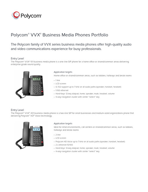
Polycom ® VVX ® Business Media Phones PortfolioThe Polycom family of VVX series business media phones offer high-quality audio and video communications experience for busy professionals.Entry LevelThe Polycom ® VVX ® 201 business media phone is a two-line SIP for small businesses and medium-sized organizations phone that delivering Polycom ® HD™ Voice technology.Application targetsIdeal for retail environments, call centers or shared/common areas, such as lobbies,hallways and break rooms• 2 line• LCD screen• Polycom HD Voice up to 7 kHz on all audio paths (speaker, handset, headset)• 2 x ethernet 10/100• Hard Keys: 12-key dialpad, home, speaker, mute, headset, volume•4-way navigation cluster with center “select” keyApplication targetsHome office or shared/common areas, such as lobbies, hallways and break rooms• 1 line• LCD screen• G.722 support up to 7 kHz on all audio paths (speaker, handset, headset)• 1/100 ethernet• Hard Keys: 12-key dialpad, home, speaker, mute, headset, volume•4-way navigation cluster with center “select” keyEntry LevelThe Polycom ® VVX ® 101 business media phone is a one-line SIP phone for a home office or shared/common areas deliveringenterprise grade sound quality.Mid-rangeThe Polycom ® VVX ® 401/411 business media phone is a color mid-range business media phone is designed for today’s office workers and attendant consoles delivering crystal clear communications.Application targetsSOHO, call center, cubicle, office desk• 12 lines or speed dials• 3.5” color TFT• 320 x 240 pixel resolution• Polycom HD Voice up to 7 kHz on all audio paths (speaker, handset, headset)and Acoustic Fence(TM) technology• 2x Ethernet 10/100 for network pass-through (VVX 401)• 2x GigE 10/100/1000 for high-performance network pass-through (VVX 411)• RJ9 Headset support with electronic hook switch• Asian character support• Hard Keys: 12-key dialpad, home, speaker, mute, headset, volume,messages, hold, transfer• 4-way navigation cluster with center “select” key• Supports Polycom VVX Expansion Module and Polycom VVX ColorExpansion Module (expandability up to 3 modules)•1 x USB for headset connectivity, storage and call recording (VVX 401 and 411)Application targetsCommon areas, dorm rooms, wall-mounted deployments, cubicle, office desk• 6 lines or speed dials• 208 x 104 pixel resolution• Polycom HD Voice up to 7 kHz on all audio paths (speaker, handset, headset)• 2 x Ethernet 10/100 for network pass-through (VVX 301)• 2 x GigE 10/100/1000 for high-performance network pass-through (VVX 310/311)• Asian character support• Hard Keys: 12-key dialpad, home, speaker, mute, headset, volume,messages, hold, transfer• 4-way navigation cluster with center “select” key• Supports Polycom ® VVX ® Expansion Module and Polycom ® VVX ® ColorExpansion Module (expandability up to 3 modules)BasicThe Polycom ® VVX ® 301/ 311 business media phone is a powerful entry-level phone for today’s cubicle workers handling a low tomoderate volume of calls delivering crystal clear communications.Application targetsKnowledge worker, busy professional’s office, call center• 12 lines appearances or speed dials• 320 x 240 pixel resolution• 3.5’’ color touch screen• Immersive capacitive touch UI• Video playback and video conferencing via USB camera accessory• Streaming media video playback• Full browser• Polycom HD Voice up to 14 kHz on all audio paths (speaker, handset, headset)and Acoustic Fence technology• 2x GigE 10/100/1000 for high-performance network pass-through• RJ9 Headset support with electronic hook switch• 2 x USB ports• Business applications integration• Supports Polycom VVX Expansion Module and Polycom VVX ColorExpansion Module (expandability up to 3 modules)• Video conferencing via optional USB cameraPerformanceThe Polycom ® VVX ® 501 is a performance business media phone that delivers best-in-class desktop productivity and unifiedcommunications for busy professionals.Application targetsExecutive, knowledge worker, busy professional’s office• 16 lines appearances or speed dials• 480 x 272 pixel resolution• 4.3’’ color touch screen• Polycom® HD Voice™ and Acoustic Fence™ technology• Immersive, capacitive touch UI• Video playback and video conferencing via external USB camera• 2x GigE 10/100/1000 for high-performance network pass-through• 2 x USB 2.0 host• RJ9 Headset support with electronic hook switch• Asian character support• Business applications integration• Microsoft ® SfB interoperability• Supports Polycom VVX Expansion Module and Polycom VVX Color• Expansion Module (expandability up to 3 modules)• Bluetooth support for wireless headset connectivityExecutiveThe Polycom ® VVX ® 601 UC executive business media phone delivers rich voice and applications experience for busy corporateexecutives and managers.WirelessThe Polycom® VVX D60 Wireless Handset is a cost-effective scalable, SIP-based, on premise, mobile communications systemApplication targetsVVX DECT solution is ideal for busy users who need to be reachable whether they areat their desk or elsewhere in their immediate workspace.• Support pairing up to 5 DECT handsets (for VVX 300, 400, 500 and 600) and1 DECT handset (VVX 101 and VVX 201)• Provisioning and Management through host phone via Ethernet• 2” TFT (178x220) color display with backlit LCD• Support for 4 simultaneous calls• HD Voice support• Range: 50m(165ft) indoor/300m(980ft) outdoor• 10/100 POE Base Station with Pass-through• DECT 1.92GHz - 1.93GHz (US), 1.88GHz-1.90GHz (EU)• 10 hours talk time, 100 hours standby• Dedicated 2.5 mm headset port (external 2.5mm to 3.5mm adapter)VVX video accessoryThe Polycom® VVX® Camera is a high quality USB video camera, designed as an easy add-on that complements the Polycom VVX 501 or VVX 601 desktop phones. The Polycom VVX Camera enables busy professionals to collaborate interactively with the best in class personal video communications experience.Application targetsExecutive, knowledge workers, busy professionals• High quality business grade video• Transmits Polycom HD Video resolution (720 p 30 fps) H.264 compression• Matches elegantly look and feel of the VVX 501 and VVX 601• Camera lens shutter for privacy• Lens mechanical adjustability to change camera angle for eye-level video calls• USB plug-and-play• Flexible—for use with VVX phone© 2018 Polycom, Inc. All rights reserved. All Polycom® names and marks associated with Polycom products are trademarks or service marks of Polycom, Inc. and are registered or common law marks in the United States and other countries. All other trademarks are property of their respective owners. No portion hereof may be reproduced or transmitted in any form or by any means, for any purpose other than the recipient’s personal use, without the express written permission of Polycom.35980-0918Polycom, Inc.1.800.POLYCOM Polycom Asia Pacific Pte Ltd +65 6389 .sg Polycom EMEA +44 (0)1753 About PolycomPolycom helps organizations unleash the power of human collaboration. More than 400,000 companies and institutions worldwide defy distance with video, voice and content solutions from Polycom. Polycom and its global partner ecosystem provide flexiblecollaboration solutions for any environment that deliver the best user experience and unmatched investment protection.Paper-based• 40 multifunctional line keys configurableas line registration, call appearance,speed dial, DSS, or BLF• Dual-color (red or green) illuminated LEDsfor line status information LCD-based• 4.3 in. LCD (480 x 272 pixel resolution)• Color graphical user interface• 28 multifunctional line keys configurableas line registration, call appearance,speed dial, DSS, or BLF• Dual-color (red or green) illuminated LEDsfor line status information• 3 page keys for additional lineappearances (up to 84 in total)Expandability • Up to three VVX Expansion Modules can be attached to any VVX phone • Provided by Polycom VVX host phone • Host phone powering options: IEEE802.3 (af/at) PoE or using a compatibleexternal AC adapter• Power Expansion modulesThe Polycom ® VVX ® expansion modules turn your VVX business media phone into a high-performance attendant console.Application targetsTelephone attendant’s desk, front desk, team manager’s deskCompatible with Polycom VVX 301, 311, 401, 411, 501, 601。
Polycom VVX 600系列高级商业媒体电话说明书
DATA SHEETPolycom® VVX® 600, 601 Business Media PhonesPremium business media phones delivering best-in-class desktop productivity for busy corporate executives and managersThe Polycom ® VVX ® 600 Series are premium business media phones designed to enhance collaboration and personal productivity.Simplicity and ease of useThe Polycom VVX 600 Series is built for executives and managers who need apowerful, yet intuitive, expandable office phone that helps them stay connected to lead your organization. Founded on the behavior common to smartphones and tablets, the intuitive gesture-based, multitouch user interface of the Polycom VVX 600 Series makes navigation easy and requires minimal training. With its combined ergonomic design, Polycom ® HD Voice™ quality and a large, high-resolution color, multitouch screen, the Polycom VVX 600 Series business media phone is ideal.Maximize productivityGive your executives and managers the best unified communications (UC) experience and the industry’s highest-quality business media phone. Designed for a broad range of environments from small and medium businesses to large enterprises, the Polycom VVX 600 Series improves personal productivity by complementing the workplace applications on their computer. Users can view and manage their Microsoft Exchange Calendars, receive meeting reminders and alerts, access the corporate directory and instant messaging/presence status right on their phone display, even while waiting for their PC to boot. They can also extend their PC’s desktop to include the Polycom VVX 600 Series screen for mouse/keyboard navigation and interaction.Best-in-class deployment and administrationThe Polycom VVX 600 Series is easy to deploy and simple to manage through the Web-based, intuitive configuration tool. Its enterprise-grade Zero Touch Provisioning and server-based configuration on large-scale deployments as well as our redirection services gives your administrators the ability to easily provision and maintain a large number of phones throughout the entire enterprise. The built-in, broad interoperability capabilities allow IT departments to leverage previous IT infrastructure investments and achieve easy integration with third-party UC and productivity applications.Highly customizable and expandableThe Polycom VVX 600 Series provides personalized information at a glance, through built-in Web applications and a digital photo frame. Polycom VVX 600 Series users access streaming content using the included video playback feature. The Polycom VVX 600 Series comes ready for future expansion modules and applications such as video- conferencing with the Polycom VVX Camera. The optional Polycom VVX Camera installs in seconds and enables the Polycom VVX 600 Series to connect into video conferences directly from the user’s desk, without requiring a costly, dedicated video- conference room.Benefits• Improve productivity for executives and managersthrough larger, color multitouch display and more line appearances • Make more efficient and productive calls with the unparalleled voice clarity of Polycom ® HD Voice™ • Turn your Polycom ® VVX ® Business Media Phone into a videoconference ready desktop videoconferencing solution with an optional Polycom ® VVX ® Camera • Improve workspacemobility through Bluetooth® headset integration • Reduce deployment andmaintenance costs—the Polycom Zero Touch Provisioning and Web-based configuration tool make the Polycom VVX 600 Series simple to deploy, and easy to administer, upgrade and maintain • Leverage previous IT infrastructure investments—deploy Polycom VVX 600 Series business media phones on your existing network without needing to upgrade your call control platform • Easily integrate with third-party Web-based UC and productivity applications for broad, standards-based, open APIsProduct specificationsUser interface features• Gesture based, multitouch capable capacitive touch-screen• 4.3 in LCD (480 x 272) resolution• 16:9 aspect ratio• Screen saver and digital pictureframe mode• On-screen virtual keyboard• Voicemail and videomail support1• Dual USB ports (2.0 compliant) for media and storage applications• Integrated Bluetooth® 2.1 EDR• Adjustable base height• Unicode UTF-8 character support. Multilingual user interface including Chinese, Danish, Dutch, English (Canada/ US/UK), French, German, Italian, Japanese, Korean, Norwegian, Polish, Portuguese, Russian, Slovenian, Spanish and Swedish Audio features• Polycom® HD Voice™ 2• Polycom® Acoustic Clarity™ technology, providing full-duplex conversations, acoustic echo cancellation and background noise suppression—Type 1 compliant (IEEE 1329 full duplex)• Frequency response: 100 Hz–20 kHz for handset, optional headset and hands-free speakerphone modes• Codecs: G.711 (A-law and μ-law), G.729AB, G.722, G.722.1, G.722.1C, iLBC• Individual volume settings with visual feedback for each audio path• Voice activity detection• Comfort noise generation• DTMF tone generation (RFC 2833and in-band)• Low-delay audio packet transmission• Adaptive jitter buffers• Packet loss concealmentHeadset and handset compatibility• Bluetooth® headset pairing (HFP/HSP)• Dedicated RJ-9 headset port• Hearing aid compatibility to ITU-T P.370 and TIA 504A standards• Compliant with ADA Section 508 Subpart B• 1194.23 (all)• Hearing aid compatible handset for magnetic coupling to hearing aids• C ompatible with commercially available TTY adapter equipmentUSB headsets are supported. (See Support site for list of compatible headsets.)Call Handling Features2• 16 lines (registrations)• Shared call/bridged line appearance• Busy lamp field• Flexible line appearance (1 ormore line keys can be assigned foreach line extension)• Distinctive incoming call treatment/call waiting• Call timer and call waiting• Call transfer, hold, divert (forward), pickup• Called, calling, connectedparty information• Local 3-way audio conferencing• 1-touch speed dial, redial• Remote missed call notification• Do not disturb function• Electronic hook switch capable• Local configurable digit map/dial planOpen application platform• WebKit-enabled full browser that supportsHTML5, CSS, SSL security and JavaScript• Supports Polycom Apps SDK andAPI for third-party business andpersonal applications• Bundled with Polycom UC Software:-Corporate directory access using LDAP-Local Voice call recording on USBflash drive-Visual conference managementNetwork and provisioning• SIP protocol support• SDP• IETF SIP (RFC 3261 and companion RFCs)• Two-port gigabit Ethernet switch-10/100/1000Base-TX across LAN andPC ports-Conforms to IEEE802.3-2005 (Clause40) for physical media attachment-Conforms to IEEE802.3-2002 (Clause28) for link partner auto-negotiation• Manual or dynamic host configurationprotocol (DHCP) network setup• Time and date synchronizationusing SNTP• FTP/TFTP/HTTP/HTTPS server-basedcentral provisioning for mass deployments• Support for Polycom Zero T ouchProvisioning• Provisioning and call serverredundancy supported1• QoS Support – IEEE 802.1p/Q tagging(VLAN), Layer 3 TOS and Diffserv/DSCP• VLAN – CDP, DHCP VLAN discovery,LLDP-MED for VLAN discovery• Network address translation support forstatic configuration and“Keep-Alive” SIP signaling• RTCP and RTP support• Event logging• Syslog• Hardware diagnostics• Status and statistics reporting• IPv4 and IPv6• TCP• UDP• DNS-SRVSecurity• 802.1X authentication and EAPOL• Media encryption via SRTP• Transport layer security• Encrypted configuration files• Digest authentication• Password login• Support for URL syntax with password forboot server address• HTTPS secure provisioning• Support for signed software executablesPower• Built-in auto-sensing IEEE 802.3afPower over Ethernet (Class 4). Backwardscompatibility with IEEE 802.3af.Approvals• Argentina CNC• South Africa ICASA• Saudi Arabia CITC• India TEC• Japan MIC/VCCI Class B• Malaysia SIRIM• Israel MOC• Singapore IDA• Taiwan NCC3• Mexico NOM-121• FCC Part 15 (CFR 47) Class B• ICES-003 Class B• EN55022 Class B• CISPR22 Class B• VCCI Class B• EN55024• EN61000-3-2; EN61000-3-3• NZ T elepermit• Korea KC• UAE TRA• Russia CU• Brazil ANATEL3• Australia RCM• ROHS compliant• China CCC331446-1017© 2017 Polycom, Inc. All rights reserved. All Polycom® names and marks associated with Polycom products are trademarks or service marks of Polycom, Inc. and are registered or common law marks in the United States and other countries. All other trademarks are property of their respective owners. No portion hereof may be reproduced or transmitted in any form or by any means, for any purpose other than the recipient’s personal use, without the express written permission of Polycom.Polycom, Inc.1.800.POLYCOM Polycom Asia Pacific Pte Ltd +65 6389 9200.sgPolycom EMEA +44 (0)1753 About PolycomPolycom helps organizations unleash the power of human collaboration. More than 400,000 companies and institutionsworldwide defy distance with video, voice and content solutions from Polycom. Polycom and its global partner ecosystem provideflexible collaboration solutions for any environment that deliver the best user experience and unmatched investment protection.Safety• UL 60950-1• CE Mark• CAN/CSA-C22.2 No. 60950-1-03• EN 60950-1• IEC 60950-1• AS/NZS 60950-1Operating conditions• T emperature: 0 to 40°C (+32 to 104°F)• Relative humidity: 5% to 95%, noncondensingStorage temperature• -40 to +70° C (-40 to +160° F)Polycom® VVX® 600 comes with• Polycom VVX 600 console • Handset with handset cord • Network (LAN) cable - CAT-5E • Quick start guide• External universal AC adaptor (optional, 48V 0.52A DC)Size (W x H x D)• 8.5 x 6 x 7 in (21 x 15 x 18 cm)Part numbers• 2200-44600-025 – VVX 600 WW PoE • 2200-44600-019 – VVX 600 Skype for Business, POE• 2200-48600-025 – VVX 601 WW PoE • 2200-48600-019 – VVX 601 Skype for Business, POEWeight• Unit weight: 2.0 lbs (0.9 kg)Unit box dimensions/weight• 11.46 x 7.9 x 3.82 in (29.1 x 20 x 9.7 cm)• 3.1 lbs (1.4 kg)Master carton quantity• 5Warranty• 1 year1. M ost software-enabled features and capabilities must be supported by the server. Please contact your IP PBX/softswitch vendor or service provider for a list of supported features.2. T o enjoy all the benefits of Polycom® HD Voice™ when using the phone in the headset mode, you must use a wideband headset.3. Planned future complianceLearn moreT o learn more about VVX, visit/voice-conferencing-solutions/desktop-ip-phones.html。
Nichicon 电容器产品说明书
2023.1根据客户需求进行系列的提案,开发的咨询商讨对应:各营业处根据客户具体设计构造进行专用产品的方案提供对应:工厂技术部在接到样品需求后进行快速响应。
并根据客户需要节奏提供参考报价对应:工厂技术部、各营业处除了技术响应以往,还会进行包括安全,物料等级登记等全面的技术支持对应:工厂技术部、质量保证部、各营业处根据客户需求对交货期进行灵活柔性管理,向客户提供高品质的产品对应:工厂生产部、各营业处Note: Please confirm product development details with your dealer.汽车应用总部邮编 604-0845 京都市中京区鸟丸通御池上电话 075-231-8461 传真 075-256-4158东京支店邮编 103-0026 东京都中央区日本桥托町14番9号 电话 03-3666-7811 传真 03-3666-7831名古屋支店邮编 460-0003 名古屋市中区锦2丁目4番3号 锦公园大楼18层电话 052-223-5581 传真 052-220-1839西日本支店邮编 604-0845 京都市中京区鸟丸通御池上电话 075-241-5370 传真 075-231-8467NICHICON (AMERICA ) CORP.927 East State Parkway, Schaumburg, Illinois 60173, U.S.A.TEL.1-847-843-7500 FAX.1-847-843-2798NICHICON (AUSTRIA ) GmbHBusinesspark Marximum, Modecenterstrasse 17, Unit 2-7-A, 1110 Vienna, AustriaTEL.43-1-706-7932 FAX.43-1-706-7933NICHICON (HONG KONG ) LTD.Unit 308, Harbour Centre Tower 1, 1 Hok Cheung Street,Hunghom, Kowloon, Hong KongTEL.852-2363-4331 FAX.852-2764-1867• THE REPRESENTATIVE OFFICEOF NICHICON (HONG KONG) LIMITED IN HANOI CITY Room 622, Floor 6, 59A Ly Thai To, Trang Tien Ward, Hoan Kiem District, Ha Noi, VietnamTEL.84-24-3936-7955 FAX.84-24-3936-8069NICHICON (SINGAPORE ) PTE. LTD.60 Paya Lebar Road, #11-17/18, Paya Lebar Square, Singapore 409051TEL.65-6481-5641 FAX.65-6481-6485NICHICON (TAIWAN ) CO., LTD.23F, No.68, Sec.5, Zhongxiao East. Road, Xinyi District, Taipei City 110, Taiwan, R.O.C.TEL.886-2-2722-2100 FAX.886-2-2722-2016NICHICON (THAILAND ) CO., LTD.1 Empire Tower, 15th Floor, Unit 1506, River Wing West,South Sathorn Road, Yannawa, Sathorn, Bangkok 10120 Thailand TEL.66-2-670-0150 FAX.66-2-670-0153NICHICON ELECTRONICS TRADING (SHANGHAI ) CO., LTD.Room 1206, Aetna Tower, 107 Zunyi Road, Shanghai, China 200051TEL.86-21-6237-5538 FAX.86-21-6237-5537• DALIAN BRANCH12F Senmao Building, 147 Zhongshan Road, Xigang District, Dalian, China 116011TEL.86-411-3989-3322 FAX.86-411-3989-3168NICHICON ELECTRONICS TRADING (SHENZHEN ) CO., LTD.Room A, 16/F, KK100No. 5016, Shen Nan Road East, Luo Hu District, Shenzhen, China 518001TEL.86-755-2294-1800 FAX.86-755-8294-5716• CHONGQING BRANCHRoom 2812, 28/F, International Trade Center (Part A), No.38, Qing Nian Road, Yuzhong District, Chongqing, China 400010 TEL.86-23-6310-8166 FAX.86-23-6310-8308• CHENGDU BRANCHRoom 1408, 14/F, Hailrun Complex (Part A), No.216, Xi Dong Da Street, Jinjiang District, Chengdu, Sichuan, China 610021 TEL.86-28-6212-9507 FAX.86-28-6212-9513NICHICON ELECTRONICS (INDIA ) PVT. LTD.Unit No.906, 9th Floor, Prestige Meridian-1, No.29 M.G. Road, Bengaluru 560001, Karnataka, IndiaTEL.91-80-4094-8661 FAX.91-80-4094-8651• DELHI OFFICEUnit No.407, 4th Floor, DLF Tower A, Jasola District Centre, New Delhi 110025, IndiaTEL.91-11-4254-8407 FAX.91-11-4254-8408• PUNE OFFICELevel 4, Prabhavee Tech Park, Baner, Pune 411045, India TEL.91-20-6723-5806 FAX.91-20-6723-6161NICHICON CORPORATION KOREA REPRESENTATIVE OFFICEB-1348, Heungdeok IT Valley, 13, Heungdeok1-ro, Giheung-gu, Yongin-si, Gyeonggi-do, 16954, KoreaTEL.82-31-8065-6366 FAX.82-31-8065-6367NICHICON (MALAYSIA ) SDN. BHD.No.4 Jalan P/10, Kawasan Perusahaan Bangi,43650 Bandar Baru Bangi, Selangor Darul Ehsan, Malaysia TEL.60-3-8925-0678 FAX.60-3-8925-0858NICHICON ELECTRONICS (WUXI ) CO., LTD.WUXI NICHICON ELECTRONICS R&D CENTER CO., LTD.Block 51-B, Wuxi National High & New Technology Industrial Development Zone, Wuxi, Jiangsu, China 214028TEL.86-510-8521-8222 FAX.86-510-8522-1170NICHICON ELECTRONICS (SUQIAN ) CO., LTD.No.18, Yangmingshan Avenue, Suzhou Suqian Industrial Park, Suqian, China 223800TEL.86-527-8097-8855 FAX.86-527-8286-8966尼吉康株式会社有关“C.A.S.E.”的市场需求 “C.A.S.E.“由梅赛德斯-奔驰于2016年提出,它展现了汽车行业未来的变革方向。
美国中央电力公司MidNite E-Panel系列产品说明书
E-Panel InstructionsModel: MNE125ST, MNE175ST, MNE250ST, MNE125AL, MNE175AL, MNE250AL,MNE175STS, MNE250STS, MNE125LT, MNE175LT, MNE250LT, MNE125ALT, MNE175ALT, MNE250ALT, MNE125AL PLUS, MNE175AL PLUS, MNE250 PLUSMNE125STM, MNE175STM, MNE250STM, MNE125ALM, MNE175ALM, MNE250ALM, MNE125STMM, MNE175SM, MNE250SMLeft and Right hand 120/240VAC versionsModel Number code:MNE---------------175-----------ST or AL----------------M-240IMPORTANT SAFETY INSTRUCTIONSSAVE THESE INSTRUCTIONS - These instructions contain important safety and operating instructions for MidNite Solar E-Panels.If you do not fully understand any of the concepts, terminology, or hazards outlined in these instructions, please refer installation to a qualified dealer, electrician or installer. These instructions are not meant to be a complete explanation of a renewable energy system.GENERAL PRECAUTIONSWORKING WITH OR IN THE VICINITY OF A LEAD ACID BATTERY, SEALED OR VENTED IS DANGEROUS. VENTED BATTERIES GENERATE EXPLOSIVE GASES DURING NORMAL OPERATION. FOR THIS REASON, IT IS VERY IMPORTANT THAT BEFORE SERVICING EQUIPMENT IN THE VICINITY OF LEAD-ACID BATTERIES YOU REVIEW AND FOLLOW THESE INSTRUCTIONS CAREFULLY.If service or repair should become necessary, contact MidNite Solar Inc. Improper servicing may result in a risk of shock, fire or explosion. To reduce these risks, disconnect all wiring before attempting any maintenance or cleaning. Turning off the inverter will not reduce these risks. Solar modules produce power when exposed to light. When it is not possible to disconnect the power coming from the Photovoltaics by an external means such as a combiner, cover the modules with an opaque material before servicing any connected equipment.Never attempt to charge a frozen battery.When it is necessary to remove a battery, make sure that the battery bank disconnect breaker is in the off position and that the PV breakers, grid breakers and any other sources of power to the inverter are in the off position. Then remove the negative terminal from the battery first.To reduce risk of battery explosion follow these instructions and those published by the battery manufacturer as well as the manufacturer of any additional equipment used in the vicinity of the batteries. Before installing the battery enclosure, read all instructions and cautionary markings in or on any connected electrical equipment.Avoid producing sparks in the vicinity of the batteries when using vented batteries. Provide ventilation to clear the area of explosive gases. Sealed AGM and Gel batteries do not under normal conditions create explosive gases. Be especially cautious when using metal tools. Dropping a metal tool onto batteries can short circuit them. The resulting spark can lead to personal injury or damage to the equipment. Provide ventilation to outdoors from the battery compartment when installing vented batteries such as golf cart T-105 batteries. The addition of a spill tray is also a good idea.Clean all battery terminals. Very high currents are drawn from the batteries; even a small amount of electrical resistance can result in overheating, poor performance, premature failure or even fire.Have plenty of fresh water and soap nearby in case battery acid contacts skin, clothing or eyes. Wear complete eye and clothing protection. Always avoid touching eyes while working near batteries. If battery acid or battery terminal corrosion contacts skin or clothing, wash immediately with soap and water. If acid enters the eyes, immediately flood with cool running water for at least 15 minutes and get medical attention immediately. Baking soda neutralizes battery acid electrolyte. Keep a supply near the batteries.Do not work alone. Someone should be in the range of your voice or close enough to come to your aid when you work with or near electrical equipment.Remove rings, bracelets, necklaces, watches etc. when working with batteries, photovoltaic modules or other electrical equipment. Power from an illuminated photovoltaic array makes a very effective arc welder with dire consequences if one of the welded pieces is on your person.To reduce the risk of injury, connect only deep cycle lead acid type rechargeable batteries. Other types of batteries may leak or burst, causing personal injury or damage.This equipment is NOT intended for use with life support equipment or other medical equipment or devices.It is the responsibility of the installer to verify compliance with all applicable codes.Before making any connections verify that the circuit breakers are in the off position including the inverter breaker. Double check allwiring before applying power.The MidNite Solar E-Panel comes standard with the basic over-current protection and disconnects required to install your renewable energy system. It can also expand to grow as your needs arise.List of features:● Steel or aluminum chassis with all the r equired openings and knock outs to aid in a NEC compliant system installation● Inverter mounts on a unique hinged door to keep the footprint of the system small as possible● Mounting brackets are included to aid in one person installations● Inverter ba ttery breaker, inverter cables and snap in grommets included*● 500 amp / 50mv shunt included for battery monitoring systems● B us bars are included for additional battery plus, PV plus and battery minus wiring● Heavy duty 175 amp AC power distribution bu s bars included● 50 amp AC input disconnect for generator or utility included, pre-wired (15amp MM series) ● 50 amp AC bypass switch for bypassing inverter circuit, pre-wired (15amp MM series)● Mounting bracket to aid in mounting an OutBack MX60 or MidNi te Classic to the side of the E-Panel*● Battery cable cover to enclose cables external to the chassis***● Inverter and charge controller mounting hardware● Rectangular cut outs for mounting a North American GFCI style AC outlet● Cut outs for mounting up to six additional 13mm wide din rail mount breakers and three ¾” wide panel mount breakers for additional circuits such as PV, wind, hydro or AC distribution ● Plastic snap in conduit and fittings from chassis to inverter for AC, BTS and control circu its (OB versions)● ETL listed to UL and CSA standards* inverter cables and charge control bracket omitted on the LT configurations*** LT versions do not have a cable cover, MM series uses the inverter battery terminal capsThe dimensioned chassis drawings above show the location of the conduit knockouts, mounting holes and mounting brackets.✓Knockouts on the top surface are directly in line with ones on the bottom surface for stacking units vertically.✓Knockouts on the lower end of each side are directly in line with each other for stacking horizontally.✓Steel powder coated units are gray textured. Aluminum powder coated units are gloss white.Door ConfigurationThe standard E-Panel comes as a left hand hinged assembly with breakers on the left side and a left hand hinged door. The door will open to the left over the breakers. If for some reason you need the breakers on the left, but the door to open to the right, then you need the optional right hand door. All breakers can be unmounted and reassembled on the right side of the chassis as is explained in this manual. Right hand E-Panels can be built special at the factory for no additional charge. Changing sides in the field is not a simple task! The left hand hinge is standard because the majority of charge controllers need to be mounted to the right side of the E-Panel. See below.1. Apollo T-80 should be a left hand hinge (heatsink is on the right)3. OutBack MF80 should be left hand hinge (No knock out on the right side of chassis)4. MX60 works equally as well on either side5. WX controller works equally as well on either side6 C40/C60 and Tri-star work equally as well on either side7. Blue Sky has the heatsink on the left, so should use a right hand hinge.See E-Panels explained on the MidNite website for exact part numbers of door options and an explanation of each E-Panel platform. E-Panels Explained will further help you in selecting the applicable E-Panel for your application.The installation begins by selecting a wall. All E-Panels are indoor rated and should not be placed outside unless precautions are made to keep rain and moisture off of the system. The wall must have suitable clearance to open the door with inverter attached. It must also have adequate clearance to operate the breakers and outlets that protrude out the sides. The NEC requires 30” clear on the wall. The E -Panel may be located anywhere within this 30 inches, however make sure you have sufficient room to the side to operate the circuit breakers. Some E-Panel installations may have circuit breakers on both sides. The NEC also requires 36 inches free and clear of obstructions in front of the E-Panel. The 36” clear area in front of all electrical panels is to provide a space to fall back into incase of electrical shock. Each E-Panel with its’ inverter will weigh close to 100 pounds so make sure your wall is adequate for this load. The mounting brackets provided will span studs on 16 inch centers. Mount the top bracket as shown at about 64-68 inches off the floor. If stacking two systems vertically, make sure the breakers fall within the NEC guidelines for height, (lowest and highest allowable). Number 10 screws with back up washers will suffice, but ¼” (6mm) hardwar e provides for a better margin of safety.A little pre-planning here will go a long way towards a successful installation. Battery boxplacement and size also need to be thought out for NEC compliance. The remote display should be approximately at eye level when attached to the E-Panel. Some installation photos below show various ways to install your system.You can make life a little easier by installing additional breakers for charge control, the inverter and such while the E-Panel is still lying horizontal on a table. Do as much of the additionalwiring as possible before hanging the E-Panel on the wall. The following pictures show some of the operations that can be done “on the bench” where access is optimal.Field installed breakers should be torqued to 20 inch pounds, then re-torqued after one hour. This is important! Wires cold flow and sometimes loosen up after the initial tightening, so don’t skip this step. E-Bay is a good source for Sturdevant Richmont torque screw drivers if you are an installer.Breakers such as charge control input and output and DC-GFP can be completely wired prior to installation on the wall. Field wiring is done at the PV, AC and DC terminal bus bars.This picture shows the Outback E-Panel mountedwith two MNEPV63 charge control breakersinstalled and an AC and DC MNSPD Surge ProtectorDevice. The upper mounting bracket can be securedto the wall and then the E-Panel chassis hung ontoit using the keyhole slots in the upper back of thechassis.Before mounting the inverter to the chassis andwith the E-Panel mounted on the wall, complete allwiring that will be coming to and going from the E-Panel. The following pictures give you some idea ofwhat to expect.The picture to the right is a Magnum 240V E-Panel.Notice it has an OutBack OBDC-GFP mounted on the leftside of this right hand hinge unit. There are a total of sixdin rail slots available on each E-Panel for customerconfiguration. This installation has two chargecontrollers. You need a breaker in the PV input and onthe DC output of the charge controller. This took up 4din rail slots for this system. The MidNite DC-GFP takesup 2 din rail slots for the 63 amp version and 2 panelmount knock out slots for the 80 amp version. Neitherone of these would work in this case, so the two circuitOutBack GFP was used. It takes up three slots on theblank plate opposite the din rails. Note the green 6AWGneutral to ground bonding wire in this picture. Theneutral to ground bond is required on all systems perNEC. Note that if this were a power back up system on autility connected home, this bonding wire would not beinstalled as it would already be there on the serviceentrance. On off-grid installations thatemploy a sub panel circuit breaker box, you can make this neutral to ground bond in the sub-panel. It is technically better to make this bond closest to the source of power (the E-Panel), but many electrical inspectors will be looking for it in the sub-panel box. It will work just fine in either location, just make sure you have adequate conductor sizes between the E-Panel and the sub-panel. Do not rely on the hinges for grounding the equipment mounted to the door.The picture to the left shows the charge control bracket suppliedin the E-Panel kit. This one is for a left hand hinged unit, so thecharge control bracket is on the right side opposite the din railbreakers.The charge control bracket supplied works with the OutBackMX60, MF80, MidNite Classic and Xantrex WX charge controllers.The Charge control bracket is secured to the E-Panel with 3 #10 x3/8” sheet metal e one more screw to secure the topbracket of charge controller and a 1” close nipple on the side asshown below. Note tha t it takes three 1” locknuts to mount the controller. One lock nut is used in between the E-Panel side and the charge controller side to act as a spacer. It may help to replace the pan head screws on the side plate with flat head screws in some cases to increase clearance.In addition to the 1” close nipple andthree locknuts, you will need plasticthreaded adapters installed on the endsof the metal threaded nipple. Theseadapters protect wires from coming intocontact with the sharp edges of themetal close nipple.Before wiring the charge controller,determine what size wire and breakerswill be required. The breakers are there to protect the wiring, notthe controller!It is very common to use the MidNite 63 amp din rail breakers for this task. Even if the charge controller is only 30 amps, it can be wired using 63 amp breakers. You will need 6AWG wire to go with those breakers though. If using one of the more powerful 80 amp charge controllers, you will need the MNEDC80 panel mount breakers. These mount on the opposite wall from the din rail breakers. 4AWG wire is required to match up with these 80 amp breakers.The flow path for the PV circuit is as follows:1.The PV + wire comes into the E-Panel and attaches to the PV+ busbar2.The PV- comes into the E-Panel and attaches to the shunt busbar. This is for charge controllers thathave a common PV- and battery- connection, (most are this way). Some charge controllers like the Xantrex XW and the Blue Sky must keep thes PV- and battery- circuits separated. The E-Panels have mounting embosses to accommodate a short white busbar to act as an isolated PV-. Use theMNSBBW for the busbar.3.From the PV+ busbar, use the appropriate gauge red wire (THHN) and connect to the PV+ INbreaker. DC breakers have polarity markings. These may be a + sign or a line and load sign.Although the PV circuit has very limited energy available and thus making polarity issues not too critical, it is best to try to get it right. This is where the fun begins.4. The + (line) marking on the breaker would seem to indicate that you should connect the PV+ tothis terminal since the PV+ is the highest potential in the system. Our testing shows this would be correct. The + side of the breaker needs to be connected to the highest potential per the breaker instructions.5.The - side of the PV in breaker goes to the charge controller PV+ input terminal.6.The output of the charge controller is sometimes marked battery+ This terminal is to connect tothe charge controller output breaker. It will not connect to the + or Line side of the breaker.7.The other side of the breaker, + or line connects to the battery plus busbar. This connection isimportant to observe polarity markings. In the event of a charge controller failure, they quite often short internally, which means they are shorting out the battery. If proper polarity is not observed, the breaker may not open and the wiring will burn up.The factory installed red battery plus bus wire is 4AWG, so it is large enough for all breaker sizes.The diagrams above show 63 amp din rail mount breakers. When 80 amp breakers and or DC-GFPare required, those breakers mount on the wall opposite the din rails. Thereare three panel mount breaker slots to accommodate the 80 ampbreakers and DC-GFP. The 80 amp DC-GFP takes up two of the three slots. The third slot will be used for the output of the 80 amp charge controller. The PV input to an 80 amp charge controller could use a 63 amp din rail mount breaker. There is no additional DC-GFP required when using the MidNite Classic controller. The DC-GFP and arc fault protector are built into the Classic controllers.Mounting the inverterThe 6 x 20mm pan head Philips screws for mounting the inverter are taptite (thread forming). Use one of these 6mm screws to pre-tap threads into the steel doors extruded funnel holes. Aluminum doors have press nuts and do not require tapping. Make sure to install all ¼” star washers to bite through the powder coating.One of the best features of the MidNite E-Panel is that one person can do all the lifting.Slip Tab A into Slot B Install inverter cablesInstall the 3.5” bushing as shown protruding up into the inverter side of the door before routing the inverter cables through the door.More tidbits to digestImportant! Torque din rail mount breakers Installing the breaker cover to 20 in lb. Wait one hour and re-torque .Six locations are available for additional 13mm wide breakers. These breakers would normally be field installed for such things as: solar, wind or hydro charge controllers, DC ground fault protector, AC and or DC distribution center and others. Remove the cut outs for the intended breakers. Each 13mm wide breaker requires removal of two cut outs. 17.5mm wide breakers require removal of three cut outs. It is important to torque the terminals to 20 inch pounds. It is highly recommended to go back over all terminations after an hour and also conduct a pull test.Doors installed,plastic conduit installed, wiring complete. Note the battery cable routing. It is important to route cables so the doors close freely without undue force. The left E-Panel battery cables came from above, but could have come fromYou may be surprised that what you thought was a tight connection actually pulls out with little effort. This is caused be a phenomenon called cold flow. Copper is a relatively soft metal and will continue to move under inadequate clamping pressure. A 20 inch pound of torque takes a lot of strength! Use the supplied UL listed plastic 2” x 6” spacers to separate AC and DC breakers if installed on the same din rail. Barriers are required per NEC between AC and DC circuits.MidNite offers 150VDC breakers in 1,2,3,4,5,6,7,8,9,10,12,15,20,30,40,50 and 63 amps. AC breakers are available in 10,15 and 20 amp sizes. Those breakers carry the UL489 and UL489A branch circuit rating. 30 and 50 amp AC breakers are available in UL1077 listed versions, but are not branch circuit rated.For OutBack installations, install the conduit pieces supplied by routing the three wires through the door and conduit before snapping the fittings into place. Snap the top right angle fitting into place first and then the one in the door. Once the length of wire has beenestablished by opening and closing the door, then cut back the three wires as required and hook up to the terminal block. The conduit in the middle of the inverter is for AC wiring. The outer conduit is for remote and battery temp sense wires.Note: Battery cables in a NEC compliant system requires cable listed for use in residential wiring.For installations requiring the OutBack surge arrestor, see pictures below. Note that this surge arrestor is only accommodated on the Stretched OutBack E-Panel.The flex conduit snaps into the sides of the surge arrestor. You will need to get an adapter to go from the 1” conduit hole in the surge arrestor housing to the ¾” flex conduit. These are readily available at your local electrical supply store or Home Depot/Lowes.This basic wiring diagram is mounted on the inside of the hinged door. Elsewhere in these instructions is a slightly expanded version of the E-Panel wiring diagram. There is an AutoCAD version of the expanded wiring diagram at This is provided so that interested parties may download and modify it to tailor their specific system configuration. When stacking two OutBack inverters, it may be required to add the OutBack PSX-240 autotransformer.OutBack and Magnum horizontal stacked systemsE-Panel parts locator, DoorSupplied insulators to achieverequired separation of AC and DCcircuitsE-Panel parts locator, internal Ground to Neutral connectionMagnum MS4448-AE & MS4024-AE system pre-wire with DC-GFPMNE175SM / MNE250SM Samlex E-Panel wiring.MNE175SM Shown.。
VIAVI Solutions T-BERD MTS 8000和6000A产品说明书
T-BERD/MTS 8000 and 6000AFIBER CHARACTERIZATIONATTENUATION PROFILE REFERENCINGPROCEDUREQUICK GUIDEThe following procedure describes how to perform a AP referencing with the use of an MTAU and a AP module into a T-BERD/MTS 8000V2. This measurement is done to ensure that the broadband source is taken into account for an accurate qualification of the fiber to test. This procedure is a two ended testNote 1: Both products must be at the same locationNote 2: it is possible to apply a new reference to an existing CD resultPlease read the entire procedure BEFORE starting.Inspect and clean connectorsBefore connecting a fiber into a test module or fiber panel, inspect and clean the bulkhead and the fiber jumper connectors.1. Connect the P5000i video inspection scope to both units USB port (any)2.3.4.5.Activate the Microscope function on both units by touching twice with your finger or stylus.6. Use the P5000i video inspection scope to verify the connector quality.7. Use appropriate cleaning material (e.g. IBC™ cleaner, cotton swab, dust air sprays, etc...) and re-inspect to confirm. Activating the AP function on the T-BERD/MTS 8000 unit1.2.3. Activate the test functions by touching twice with your finger or stylus. Wait for the tuning process of the1. tab2. SelectConnecting both test sets1. Inspect and clean connectors of the fiber jumpers, the COM port of the T-BERD/MTS 8000 and the OTDR port of theT-BERD/MTS 6000A using the P5000i inspection scope.2. Connect the fiber jumper 1 to the T-BERD/MTS 8000 COM port of the MTAU module and to the mating adapter.3. Connect the fiber jumper 2 to the T-BERD/MTS 6000A OTDR module and to the mating adapter.Patchcord inspection Bulkhead and test port inspectionT-BERD/MTS 8000T-BERD/MTS 6000A1.activate the BBS function 2.3. Touch the soft key to turn the source on4. Touch the softkey to position the test mode as AP1. 2. Touch the tab.3. SelectNote: BBS serial number is displayed on the T-BERD/MTS6000A Results page6. Confirm by pressing YES when the message pops up.Note: A message “valid Reference” is displayed in green. If not, verify proper connector cleanliness and interconnections then restart referencing processSaving a reference file on the T-BERD 80001. Once the reference measurement is done, press key2.Select3.Enter the source serial number under4.Press the key5. Give it a namexxx being the BBS serial number, so that you know itcontains the reference for T-Berd 6000A SN xxx.Note 1: This file (ex: T-BERD6000A CD REF SN xxx.ocd” into your T-BERD 8000 unit.Note 2: Repeat the referencing and saving steps for as many T-BERD 6000A and T-BERD 8000 units Note 3: It’s recommended to save the reference files into a dedicated directory for easy locationLoading a reference file into a T-BERD 80001. Press the “file” hard key2.Select the directory where the reference files are located. For example:3.Highlight the file that has the requested T-BERD/MTS 6000A reference4.Press the soft key5. Select6.Note: You now see 2 reference boxes On says and that shows the current reference loaded into the test unit. Thelower box says and that shows the reference information for the trace that is currently loaded (your new reference). It also shows the filename so you can see if it is “T-BERD6000A CD REF SN xxx.ocd”, for example.7. Under the list, select8. Press the soft key9. The message appears. SelectNote: The date and s/n of the reference appear into the list. You know the new reference is loaded.10. Follow the above steps to change the reference again。
- 1、下载文档前请自行甄别文档内容的完整性,平台不提供额外的编辑、内容补充、找答案等附加服务。
- 2、"仅部分预览"的文档,不可在线预览部分如存在完整性等问题,可反馈申请退款(可完整预览的文档不适用该条件!)。
- 3、如文档侵犯您的权益,请联系客服反馈,我们会尽快为您处理(人工客服工作时间:9:00-18:30)。
BBEF北京北广电子集团有限责任公司LEVITON北广电子集团美国立维腾销售中心美国立维腾综合布线产品松下电工National安防监控Jvc背景音乐BBEF扩音卫星电视电视电话会议系统公司简介一及产品特色1.北京北广电子集团有限责任公司北京北广电子集团有限责任公司(原北京广播器材厂)是全面通过ISO9000认证的大型一类国有企业,是闻名全国享誉世界的广播电视设备制造商。
是中国公共广播(有线电视)、无线广播、电视发射设备生产的奠基者。
其中广播电视发射设备的国内占有率近90%,这是国内外任何一家企业都不能比拟的。
北京北广电子集团拥有国家级的技术开发中心和与国内外著名大学科研机构共建的高科技实验室,领导着国内行业技术的发展。
不断引进国外先进技术和管理,创造了63项中国第一,填补了近200项国内空白,被授予国家级高新技术企业、国家263计划CIMS应用示范企业称号。
发展到今天,北京北广电子集团的产品已纵横广播电视、微波传输、通讯导航、雷达显示、音视频设备、有线电视、移动通讯、保安监控、宽带网结构化布线、公共广播系统、同声传译系统、会议系统、音响工程等诸多领域。
特别是公共广播产品在集团高科技术的支持下,成为国内此类产品全面通过ISO9000认证的第一家。
目前产品远销国内外,深受广大用户的好评。
“让中国人民听好广播、看好电视”。
是我们的宗旨;追求高新技术品位与卓越的质量是我们的奋斗目标;优质、诚信是我们一贯遵循的原则。
我们将一如既往,竭诚为广大用户提供优质产品和最佳服务。
2.美国立维腾制造公司LEVITON百年前当爱迪生为人类创造了点亮光明的电灯的同时,LEVITON这个名字同此发明一起跃然于这一新的领域中。
众所周知,没有连接电灯泡与电线传输的路径,我们并不能享受夜间光明给大众带来的欢乐。
正是基于这一必备的连接设备创制的理念,LEVITON公司的创始人们发明了沿用至今的灯头连接,从此LEVITON公司在电子、电气连接领域中不断耕耘拓展,一直走在行业的潮头。
为民用及工业各层面不断提供连接产品,并一直信守着一个承诺:Building a Connected World“建造一个链接的世界”做为公司百年历史的坐标一直指引着遍布全球的公司员工努力开创为业界称道的行业领导者的形象。
正因为众志成城的努力,人们才会发现,在美国,90%的家用灯光连接部件均是出自LEVITON(立维腾)制造公司。
每一个美国家庭正在享用着100件左右的LEVITON 生产的产品。
可以毫不夸张的说,LEVITON的产品与大众生活息息相关。
LEVITON公司带来的不仅仅是涉及大众生活中无所不在的连接产品,而是光明。
LEVITON制造公司(Leviton Manufacturing Company)总部设在美国纽约,员工总计为12,000人,销售网络遍布全世界45个国家和地区。
是一家实力相当雄厚的有着98年历史辉煌历史的跨国集团。
立维腾制造公司是美国电子联结产业中的领军公司,现有产品种类将近30000种,每天生产320万个不同产品并行销到美国本土及世界各地,借以满足不同领域中的各种需求。
我们拥有制造公司拥有先进的生产工艺及管理体系以保持LEVITON在98年激烈的行业竞争中仍然领先。
LEVITON在行业中的取胜之道是不断为市场提供革新性产品及令客户称道的客户服务。
LEVITON还拥有一套强有力的市场支持及推广系统。
客户,分销及OEM渠道里均有专职市场扶植部门,以争取到为本部及商业伙伴共同盈利的目标。
LEVITON的全方位市场拓展包括广告,产品资料更新,销售协助,奖励制度,共同推广及深度产品培训。
LEVITON制造公司旗下包括四大部分:AMERICAN INSULATED WIRE(美国绝缘线缆公司),PACIFIC ELECTRICORD(太平洋电线公司),LIGHTING CONTROL DIVISIION(立维腾灯控)及LEVITON VOICE & DATA DIVISION (立维腾语音数据分部)。
与北京合作伙伴合作之初以涉及立维腾语音数据分部的结构化产品为主。
未来将有更广泛的合作前景。
立维腾语音数据分部是美国五大布线商之一,多年来我们的销售业绩一直位于三甲之列。
在30多家布线产品的厂商中占有着很高的市场分额。
在激烈的布线市场竞争中,一直以产品更新换代快,质量卓越,客户服务针对性的诸多优势而多年来屹立与竞争厂商中。
立维腾语音数据分部是行业协会BiCSI,CEDIA,EIA/TIA等标准组织成员,参与制定行业标准的会员公司之一。
协助设定了一系列现今仍在执行的行业标准。
作为美国主要的连接系统供应商之一,立维腾语音数据分部的产品品种齐全(4400多种),包括3类,5类,超5类,增强型超5类,6类,光纤布线系统,智能家居布线(包括宽带接入系统)等系列,所有产品经过相关ISO 9000系列认证,符合UL,EIA/TIA 等国际标准,具有最优的性能价格比,并能保证产品的最高品质。
由于公司始终定位产品质量为取胜之道,所以是厂商竞争中唯一向客户提供终生系统保证的公司。
公司既是美国五大结构化布线厂商之一,同时也是最主要的智能化家居布线系统供应商。
并且一直继承并恪守总公司对社会的承诺—“建造一个链接的世界”(Building a Connected World)。
立维腾语音数据分部是由原立维腾电讯公司和立维腾光纤科技合并而组成的全方位提供语音数据公司。
产品涵盖面涉及全面的网络需求:铜类及光纤产品;语音;数据;声像连接系统而构成全方位的布线架构。
鉴于立维腾语音数据分部是行业BiCSI及TIA标准组织成员,我们提供的产品将无疑为客户提供高品质及优越性能。
立维腾语音数据部主要产品及特色1.eXtreme™ 6 超6类∙带宽达到350MHz, 远远超过6类标准草案∙是世界上性能最优秀产品之一(美国独立实验室测试认证)∙世界上少有的达到元器件级标准, 高于常规信道级标准∙真正提供全系列6类产品的公司∙产品包括13色6类模块, 24口&48口6类配线架, 各种长度各种色彩6类跳线等.2.GigaMax™ 5e 超5类∙带宽达到250MHz∙包括信道级和元器件级产品∙产品包括13色RJ45模块, 110 19”配线架和110 打线式配线架及各种跳线3.Category 5 5类∙满足100 BASE-T, 155M ATM 等网络传输∙提供13色RJ45模块, 110配线架, 标准跳线等∙其中模块采用无线路板结构, 双镀层, 镀金层达到50微米4.Opt-X 光纤系列∙提供Thread-Lock, Fast Cure系列光纤接头, 包括ST®, SC, FC, MT-RJ,LC 等单模/多模接头.∙提供6-72口墙装式和机架式光配线架∙各种光纤跳线和光纤尾纤5.Thread-Lock 系列光纤接头∙提供ST®, SC, FC等单模/多模接头∙是世界上唯一的可重复使用的光纤接头∙安装时无需环氧树脂和烤炉, 无需压接∙只需一把钳子, 2分钟接可完成安装6.Thread-Lock Versa-Cleave™工具∙小巧灵活的光纤切割工具∙光纤切割平整光滑, 大大减少研磨时间∙切割时, 只需象秒表一样按一下既可.7.Versi-Duct™理线系列∙新型滑槽式全封闭理线架∙包括单面/双面, 1U/2U水平理线架和垂直理线架终生保证立维腾的产品具有最高的质量并且提供业界最过硬的质保。
我们的终生质保包括零部件和它的性能,保证您的由CCS安装的系统不仅支持现在的所有应用,而且支持将来TIA-568-B标准所提出的各种应用。
这个质保包括所有CCS系统中的产品,包括整个布线系统中使用的材料品质以及在安装过程中发生的问题。
另外,立维腾的“全系统证书”涵盖整个布线系统—光纤和铜缆—从水平方案到主干系统。
对于将来系统增减,移动和跳接都不用担心,因为立维腾的专业安装人员会为您的系统性能提供终生的维护。
附:2002年进入中国大陆主要用户及样板工程斯坦福大学(702座建筑物)本田汽车制造公司(底特律)北京电子城科技大厦东方出版社上海市卢湾区房地产交易中心嵊州公安局大楼上海电信数码通(8万用户) 35届亚洲银行上海年会中国石化上海石油零售分公司西安翻译学院(5000点)北京国资委四川成都科技广场(11000点) 北京市交通管理局西城分局北京市月坛大厦(6类1800点)国土资源部北京市第二监狱北京市丰台区交通管理局山东东营法院山东电信临沂电信江苏电信常州电信中国网通西安铁通哈尔滨联通公司营业厅综合布线系统工程黑龙江省七台河发电厂综合布线系统工程 5栋楼黑龙江瑞兴科技发展股份有限公司综合布线系统工程齐齐哈尔电力局新楼网络综合布线系统工程齐齐哈尔高压局家属区新楼综合布线工程 3栋7层楼哈尔滨第32中学网络综合布线系统工程哈尔滨工业大学博士办公楼网络综合布线系统工程哈尔滨立民开发区特力公司商服办公楼系统工程哈尔滨立民开发区裕发新村住宅综合布线工程哈尔滨立民开发区金衡基住宅综合布线工程宁波信息港近百个智能化小区(35万用户)广播系统工程主要业绩北京西客站贵宾室北京第八十中北京光彩体育馆国务院第二招待所礼堂北京广播学院校园国际俱乐部和平门烤鸭店宴会厅北京体育学院体育馆北京天坛公园北京林学院体育场北京市高级人民法院北京中医药学院北京东城区人民法院北京联合大学一机部老干部活动站红塔礼堂北京樱花宾馆中国文学艺术界联合会剧院中日友好医院会议厅天津市政府会议室北京松下通讯设备有限公司石家庄军械技术学院俱乐部北京服装进出口公司大楼廊坊体育馆北京万方商场秦皇岛港务局二公司礼堂西单首都机场超市石家庄电力局礼堂北京雪银大厦华北石油采油二厂俱乐部礼堂北京朝阳副食品总公司张家口市文化广场宣武区人民法院济南炼油厂俱乐部良乡输配电公司俱乐部济南化肥厂俱乐部天津市老干部俱乐部济南7422厂俱乐部天津市老干部舞厅青岛人民会堂天津市政府404实验室莱西县南墅石墨矿俱乐部天津火车站西站潍坊市柴油机厂俱乐部杭州大剧院泰山风景区山东大学礼堂沧州火车站良乡影剧院德州火车站黄鹤楼延安影剧院湖北省歌舞团西安飞机制造公司礼堂武汉洪山广场丹东火车站武汉荆门炼油厂俱乐部金州火车站长沙4435厂俱乐部沈阳铁路局文化宫韶阳体育馆长春火车站韶阳纺织厂礼堂大庆油田第七采油厂俱乐部四川宜宾市体育馆七台河矿务局俱乐部湛江南海西部石油公司电影院乌鲁木齐自治区广场广东湛江体育场克拉玛依百口泉采油场俱乐部太原铁路三局文化宫石嘴山市工人文化宫左权县职工俱乐部内蒙古自治区政府礼堂、放映厅大同雁北影剧院内蒙古自治区广场闻喜3534厂俱乐部内蒙古自治区体育场交城县剧院呼和浩特大会堂西山矿务局剧院弥渡县影剧院山西太原武警俱乐部云南昆明五华区体育场云南昆明五华区体育馆安防监控与卫星电视弱电系统工程人民大会堂首都机场西昌卫星基地中南海电视会议系统宝钢首钢二汽中国航天发射中心中油总院国务院第二招待所中央电视台彩电中心中国外交学院外贸培训中心北方医院王府饭店丽都假日饭店首都饭店西苑饭店燕山大酒店友谊宾馆燕翔饭店金都假日饭店发展大厦希尔顿酒店中日友好交流中心天伦王朝饭店幸福大厦雅宝大厦北京昆仑饭店亚细亚广场亚太大厦北人大酒店亚运村汇宾大厦丽晶花园北京王府饭店。