超声波毕设文献综述
超声波测距之文献综述

文献综述一、引言伴随着时代的发展我国经济水平的提高,对于先进的技术的需求也越来越多。
超声波测距技术在越来越多的领域发挥着作用。
如今的石油勘测技术、汽车的倒车报警技术、汽车的维修与检测技术、现代植保机械与施药技术、物体识别、海洋测量等等。
由此可见超声波测距的前景还是十分广阔的,这也是选择超声波测距作为我的毕业课题的一个原因。
二、超声波测距原理超声波是超过人类听力范围的一种特殊的波,同样具有声波传输的最基本的物理特性。
超声波测距是一种非接触式的检测方式,与激光测距、红外线测距相比,超声波对外界光线、色彩和电磁场不敏感,对于被测物体处于黑暗、有灰尘、烟雾、电磁干扰大或者有毒等恶劣的环境下有一定的适应能力,同时超声波还具有指向性强,能量消耗缓慢以及在介质中传播距离远等优点。
超声波的工作原理是通过反射来实现的。
通过测量发射超声波和遭遇物体反射回来的反射波的时间间隔t,就可以通过公式计算出超声波发射点和观测点之间的距离S,如图1所示。
公式如下:S = 1/2vt式中v:超声波音速(声速)340m/s t:超声波的时间间隔。
S三、主要设计根据罗兆纬的《超声波测距系统设计》、王占选的《具有温度补偿功能的超声波测距系统设计》文章中所采取的系统整体结构设计,结合实际我的系统由为四部分组成,如图1所示。
分别是:数码管显示模块、TMS320F28027DSP芯片、超声波传感器模块、温度传感器模块。
TMS320F28027芯片用作控制单元,超声波传感器HC- SR04 用于超声波的发送以及回波信号的接收,温度传感器DS18B20 用于对外界环境温度的采集,数码管用于对目标与障碍物的距离进行显示。
1.超声波传感器模块王占选的《具有温度补偿功能的超声波测距系统设计》文章中超声波传感器HC - SR04 集超声波的发送和接收功能于一体,可以非常方便地提供 5 ~400 cm范围的非接触式距离感测功能。
引脚由上而下依次为电源引脚、超声波发送的触发引脚、回波信号的响应引脚以及接地引脚。
超声波探伤论文-超声波探伤毕业论文

超声波探伤论文-超声波探伤毕业论文摘要本毕业设计的课题是板材焊缝超声波探伤测试。
主要任务是在掌握过程设备制造流程和焊接缺陷及其产生原因的基础上,研究超声波探伤技术在钢制压力容器对接焊接接头探伤检测中的应用,并给出焊缝返修的具体方案。
本文详述了国内外超声检测技术的发展和现状,并在简述过程设备制造、焊接及无损探伤的基础上详细介绍了超声波探伤技术及其在焊缝无损探伤中的应用及评定等级和注意事项。
针对给定的板材焊缝,通过实验检测该焊缝的缺陷,本文详细介绍了试块选用,设备调试,现场探伤中的常见问题及解决方法。
同时给出了现场探伤、缺陷定位和长度测量的具体方法,并通过GB11345-89标准对试验中检测到的缺陷进行了等级评定并得出了检测工艺卡。
关键词:焊缝;超声波探伤。
AbstractThe task of the graduation design is the plate weld ultrasonic testing. The main task is to master the process equipment manufacturing and welding defects and its causes, study of ultrasonic flaw detection technology in steel pressure vessel butt welded joint flaw detection, and gives the concrete plan of the weld repairing. This paper describes the domestic and foreign development and present situation of ultrasonic detection technology, and in the process equipment manufacturing, welding and nondestructive testing based on detailed introduces the ultrasonic detection technology and its application in weld NDE and rating and matters needing attention. For a given plate welding, the weld defects detection by experiment, this paper introduces the test block selection, equipment commissioning, on-site inspection of the common problems and solutions. At the same time provides on-site testing, defect location and length measurement methods, and through the GB11345-89 standard to test the detected defects were rating and the detection process card.Key words: Weld; ultrasonic testing目录1.1选题的背景及意义过程设备是各个工业部门不可缺少的重要生产设备,用于供热、供电和储存各种工业原料及产品,完成工业生产过程必需的各种物理过程和化学反应。
超声波测距系统(论文设计)正文、结论、参考文献等

1 绪论1.1 超声波技术的广泛应用超声的研究和发展,与媒质中超声的产生和接收的研究密切相关。
1883年Galton 首次制成超声气哨,其原理是将压缩气体经过狭缝喷嘴形成气流,吹动圆形刀口振动形成共振腔,从而产生超声。
此后又出现了各种形式的汽笛和液哨等机械型超声换能器。
由于这类换能器成本低,所以经过不断改进,至今仍广泛地用于超声处理技术中。
20世纪初,电子学的发展使人们能利用某些材料的压电效应和磁致伸缩效应制成各种机电换能器。
1917年,法国物理学家Paul Langevin用天然压电石英制成了夹心式超声换能器,并成功地应用于水下探测潜艇。
随着军事和国民经济各部门中超声应用的不断发展,又出现更大超声功率的磁致伸缩换能器,以及各种不同用途的电动型、电磁力型、静电型等多种超声换能器。
材料科学的发展,使得应用广泛的压电换能器也由天然压电晶体发展到机电耦合系数高、价格低廉、性能良好的压电瓷、人工压电单晶、压电半导体以及塑料压电薄膜(PVDF)[1]等。
产生和检测超声波的频率,也由几十千赫提高到上千兆赫。
产生和接收的波型也由单纯的纵波扩大为横波、扭转波、弯曲波、表面波等。
如频率为几十兆赫到上千兆赫的微型表面波都己成功地用于雷达、电子通信和成像技术等方面。
利用超声波作为定位技术是蝙蝠等一些无目视能力的生物作为防御及捕捉猎物生存的手段,也就是由生物体发射不被人们听到的超声波(20kHz以上的机械波),借助空气媒质传播由被待捕捉的猎物或障碍物反射回来的时间间隔长短与被反射的超声波的强弱判断猎物性质或障碍位置的方法。
由于超声波的速度相对于光速要小的多,其传播时间就比较容易检测,并且易于定向发射,方向性好,强度好控制,因而人类采用仿真技能利用超声波测距。
超声波测距是一种利用声波特性、电子计数、光电开关相结合来实现非接触式距离测量的方法。
它在很多距离探测应用中有很重要的用途,包括非损害测量、过程检测、机器人检测和定位、以及流体液面高度测量[2]等。
毕业设计论文-超声波测量

摘要液位测量广泛用于石油、化工、气象等领域。
超声波液位计是众多液位计中发展较快、应用较多的一种液位测量仪表。
它是利用超声波在同种介质中传播速度相对恒定以及碰到障碍物能反射的原理研制而成的,具有非接触、高精度、价格低廉、使用方便等优点。
近年来,随着高速数字信号处理技术与微处理器技术的进步,超声波液位计得到了长足的发展。
本文主要针对封闭式储存罐内的液位测量仪器进行了设计研究,利用无损测量技术,使用脉冲回波法进行液位测量,采用低功耗16位单片机MSP430作为主控芯片,利用超声波换能器产生的1MH Z超声波作为测量信号;用液晶显示测量的结果。
在设计中考虑到了误差的产生,并利用硬件部分和软件算法最大限度的减少误差,提高了系统的测量的精度。
关键字:液位计;超声波;MSP430单片机AbstractLevel measurement is widely used in the fields of oil industry、chemical industry and meteorology. Among all the level measurement instruments, ultrasonic level measurement instrument is developed faster and used more widely. Ultrasonic wave propagates at the constant speed in the same medium and reflects when meets with obstacle. Based on this theory, ultrasonic level measurement instrument is manufactured. The main merits of ultrasonic level measurement is non-contact, high accuracy, low of price, convenience of using and so on. In recent years, with the high development of high speed digital processing and micro-processor, ultrasonic level measurement instrument has obtained a great advancement.This system adopt low consumption 16 one-chip computer MSP430 as the top management chip , use 1MHz ultrasonic wave that the transducer produces as the signal of measuring; Reveal the result measured with the LCD. Consider the production of the error in the design, utilize the hardware part and maximum reduction error of software algorithm, have improved the precision of systematic measurement.Keywrod: level measurement;ultrasonic wave;MSP430目录摘要 (Ⅰ)A bstract (Ⅱ)第一章绪论 (1)1.1 液位计的现状及发展趋势 (1)1.1.1 综述 (1)1.1.2 液位计的现状 (1)1.1.3 液位测量仪表的发展趋势 (3)1.2 超声波液位计研究目的及其可行性 (3)1.3 本课题研究的内容 (3)第二章超声波液位计的测量原理 (5)2.1 超声波的基本特性 (5)2.2 超声波传感器 (6)2.3 超声波液位计的测量原理 (6)第三章系统硬件设计 (8)3.1 MSP430芯片的选择及其特点 (8)3.2 基于MSP430的超声波液位计的总体设计 (8)第四章系统软件设计 (10)4.1 EW430简介 (10)4.2 应用程序整体设计 (10)4.3 信号的采集与计算 (11)4.4 键盘程序设计 (16)4.5 LCD显示程序设计 (19)4.6 温度测量程序设计 (20)4.7 编程注意事项 (22)第五章误差与干扰分析 (24)5.1 温度的影响 (24)5.2 直达波的影响 (24)5.3 传播距离 (24)5.4 测量的随机性 (24)第六章调试分析 (25)6.1 LCD显示程序的调试 (25)6.2 键盘程序的调试 (25)6.3 温度测量程序的调试 (25)第七章总结 (26)7.1 本文完成的工作 (26)7.2 存在的问题及展望 (26)致谢 (27)参考文献 (28)附录 (29)第一章绪论1.1液位计的现状及发展趋势1.1.1 综述液位测量在石油、化工、气象等部门应用广泛,实现无接触、智能化、高精度、低功耗是液位计目前的发展方向。
超声波检测的文献综述
超声波检测的文献综述第一篇:超声波检测的文献综述文献综述—基于超声波的包覆层固化深度的检测方法一、本课题的研究背景及意义对材料表面保护、装饰形成的覆盖层,如涂层、镀层、敷层、贴层、化学式成膜等,统称为包覆层[1]。
实际上,材料表面的包覆层厚度对产品的使用性能和使用寿命影响极大,因而,包覆层厚度的检测对所有表面技术要求较高的产品都是必须的。
由于众多包覆层的厚度范围很大,从纳米尺度的气象沉积、离子注入层到毫米级的热喷涂层、堆焊层、渗碳层等,故不同厚度的测量也有许多不同的方法,这些方法均是利用不同的原理测出不同尺度范围的表面包覆层的厚度[3]。
包覆层厚度的测量,根据被测包覆层是否损坏可分为有损测厚和无损测厚两大类。
有损测厚主要有:阳极溶解库仑法、光学法、化学溶解法、轮廓法等;无损测厚有:磁性法、涡流法、射线法、电容法、超声波法、光学法等[3]。
这些方法各有其特点、适用性及局限性,在实际测量时,我们应考虑到包覆层厚度、零件形状与尺寸、覆层成分和测量环境等多种因素,选择适合的测量方法才能获取最可靠的结果。
现代无损检测的定义是:在不损坏试件的前提下,以物理或化学方法为手段,借助先进的技术和设备器材,对试件的内部及表面的结构,性质,状态进行检查和测试的方法,而超声波检测作为无损检测的方法之一,最早开始于1930年,是利用进入被检材料的超声波对材料表面或内部缺陷进行检测,而利用超声波进行材料包覆层厚度的测量也是常规超声波检测的一个重要方面[5]。
超声波被用于无损检测,主要是因为有以下几个特性:①超声波的波束能集中在特定的方向上,在介质中沿直线传播,具有良好的指向性;②超声波在介质中传播过程中,会发生衰减和散射;③超声波在异种介质的界面上将产生反射、折射和波型转换,可以获得从缺陷界面反射回来的反射波,从而达到探测缺陷的目的;④超声波的能量比声波大得多,对各种材料的穿透性较强;⑤超声波在固体中的传输损失很小,探测深度大。
超声波测距仪的设计【文献综述】
文献综述电子信息工程超声波测距仪的设计参考的文献资料主要是在学校图书馆的综合书库、期刊室、中国期刊网上搜集的,主要是关于单片机、超声波及超声波测距仪的一些文章和书本。
在此,根据参考的内容,我将我所参考的资料进行了分析和分类,如下:刘凤然的《基于单片机的超声波测距系统》和葛健强的《基于CPLD的超声波测距仪研制》主要是讲用单片机控制超声波的轮流发射,并且通过单片机记录和读取发射超声波和接收到回波的时间差,进而计算出测量的距离。
①超声波发生器为了研究和利用超声波,人们已经设计和制成了许多超声波发生器。
总体上讲,超声波发生器可以分为两大类:一类是用电气方式产生超声波,一类是用机械方式产生超声波。
电气方式包括压电型、磁致伸缩型和电动型等;机械方式有加尔统笛、液哨和气流旋笛等。
它们所产生的超声波的频率、功率和声波特性各不相同,因而用途也各不相同。
目前较为常用的是压电式超声波发生器。
②压电式超声波发生器原理压电式超声波发生器实际上是利用压电晶体的谐振来工作的。
它有两个压电晶片和一个共振板。
当它的两极外加脉冲信号,其频率等于压电晶片的固有振荡频率时,压电晶片将会发生共振,并带动共振板振动,便产生超声波。
反之,如果两电极间未外加电压,当共振板接收到超声波时,将压迫压电晶片作振动,将机械能转换为电信号,这时它就成为超声波接收器了。
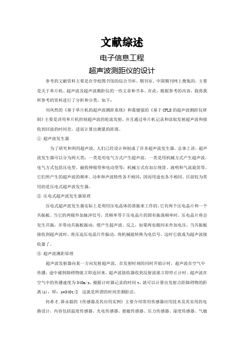
③超声波测距原理超声波发射器向某一方向发射超声波,在发射时刻的同时开始计时,超声波在空气中传播,途中碰到障碍物就立即返回来,超声波接收器收到反射波就立即停止计时。
超声波在空气中的传播速度为340m/s,根据计时器记录的时间t,就可以计算出发射点距障碍物的距离(s),即:s=340t/2 这就是所谓的时间差测距法。
何希才,薛永毅的《传感器及其应用实例》主要介绍常用传感器应用技术及其实用的电路设计,内容包括温度传感器、光电传感器、慈敏传感器、压力传感器、湿度传感器、气敏传感器、超声波传感器、红外传感器等的原理、特性参数及选用原则,并提供较多的应用电子实例。
超声波控制系统文献综述

单位代码01学号____分类号TN7 ___密级___ _____文献综述基于超声波通信的多路控制系统院(系)名称专业名称学生姓名指导教师20年月日黄河科技学院毕业设计(文献综述)第1页基于超声波通信的多路控制系统摘要随着电子、通信技术的不断发展,对于系统以及电器机械的控制经历了由有线到无线的,由人工到智能的飞跃式发展。
特别是无线控制技术的出现和发展,大大方便了人们的生活和生产活动。
本文介绍的基于超声波控制系统是基于超声波发射和接受电路、编码译码电路等,实现数据的发射和传输,从而最终实现对多路系统的控制。
本设计采用了T∕R40-16作为超声波传感器,PT2262∕2272作为编码译码芯片,这些核心元器件功耗低,性能稳定,价格低廉,而且信号传输采用的超声波通信具有具有定向性好、能量集中、传输过程中衰减较小、抗干扰能力较强等优点,从而使本设计结构简单、性能稳定、安全性高、价格低廉等优点,相信会有很好的应用前景。
关键词:超声波发射接收,PT2262编码,2272译码,T∕R40-16超声波传感器黄河科技学院毕业设计(文献综述)第2页引言人类对系统的控制经历了从无到有、从简单到复杂的过程,同时由于新型大规模遥控集成电路的不断出现,使无线控制技术有了日新月异的发展,其智能化的程度越来越高,甚至可以完全由计算机操控,由计算机发送指令,实现无线远程控制,像导弹火箭卫星等的发射、控制,生活中同样需要无线控制系统,无线控制系统大大方便丰富了人们的生活,像电视的遥控板,遥控玩具等,同时也可以使人们远离一些危险场所,对一些可能危害人类健康、安全的机械等实现无线控制。
本文将介绍一种比较简单的超声波通信的多路控制系统,这种控制系统结构简单、价格低廉,可用于生产控制,实时监测和事实报警灯方面。
1 超声波控制系统的组成概述超声波控制系统主要由发射系统和接收系统2大部分组成。
超声波控制系统的工作原理是首先通过输入所需控制电路的位号,同时启动编码电路产生带有地址编码信息和开关状态信息的编码脉冲信号,再通过超声波电发射电路将该信号发射出去。
超声波开题_rd

本科毕业设计(论文)开题报告学生姓名黄哲立学号08B08090231指导教师詹振球学院(系)机电学院专业微电子学交稿日期2011年12月2日教务处制一、开题报告二、阅读文献目录三、文献综述四、文献翻译注意:请将外文文献原文复印件附在后面。
Ultrasonic distance meterDocument Type and Number:United States Patent 5442592Abstract:An ultrasonic distance meter cancels out the effects of temperature and humidity variations by including a measuring unit and a reference unit. In each of the units, a repetitive series of pulses is generated, each having a repetition rate directly related to the respective distance between an electroacoustic transmitter and an electroacoustic receiver. The pulse trains are provided to respective counters, and the ratio of the counter outputs is utilized to determine the distance being measured.Publication Date:08/15/1995Primary Examiner:Lobo, Ian J.1、BACKGROUND OF THE INVENTIONThis invention relates to apparatus for the measurement of distance and, more particularly, to such apparatus which transmits ultrasonic waves between two points.Precision machine tools must be calibrated. In the past, this has been accomplished utilizing mechanical devices such as calipers, micrometers, and the like. However, the use of such devices does not readily lend itself to automation techniques. It is known that the distance between two points can be determined by measuring the propagation time of a wave travelling between those two points. One such type of wave is an ultrasonic, or acoustic, wave. When an ultrasonic wave travels between two points, the distance between the two points can be measured by multiplying the transit time of the wave by the wave velocity in the medium separating the two points. It is therefore an object of the present invention to provide apparatus utilizing ultrasonic waves to accurately measure the distance between two points.When the medium between the two points whose spacing is being measured is air, the sound velocity is dependent upon the temperature and humidity of the air. It is therefore a further ob ject of the,present invention to provide apparatus of the type described which is independent of temperature and humidity variations.2、SUMMARY OF THE INVENTIONThe foregoing and additional objects are attained in accordance with the principles of this invention by providing distance measuring apparatus which includes a reference unit and a measuring unit. The reference and measuring units are the same and each includes an electroacoustic transmitter and an electroacoustic receiver. The spacing between the transmitter and the receiver of the reference unit is a fixed reference distance, whereas the spacing between the transmitter and receiver of the measuring unit is the distance to be measured. In each of the units, the transmitter and receiver are coupled by a feedback loop which causes the transmitter to generate an acoustic pulse which is received by the receiver and converted into an electrical pulse which is then fed back to the transmitter, so that a repetitive series of pulses results. The repetition rate of the pulses is inversely related to thedistance between the transmitter and the receiver. In each of the units, the pulses are provided to a counter. Since the reference distance is known, the ratio of the counter outputs is utilized to determine the desired distance to be measured. Since both counts are identically influenced by temperature and humidity variations, by taking the ratio of the counts, the resultant measurement becomes insensitive to such variations.3、BRIEF DESCRIPTION OF THE DRAWINGSThe foregoing will be more readily apparent upon reading the following description in conjunction with the drawing in which the single FIGURE schematically depicts apparatus constructed in accordance with the principles of this invention.4、DETAILED DESCRIPTIONReferring now to the drawing, there is shown a measuring unit 10 and a reference unit 12, both coupled to a utilization means 14. The measuring unit 10 includes an electroacoustic transmitter 16 and an electroacoustic receiver 18. The transmitter 16 includes piezoelectric material 20 sandwiched between a pair of electrodes 22 and 24. Likewise, the receiver 18 includes piezoelectric material 26 sandwiched between a pair of electrodes 28 and 30. As is known, by applying an electric field across the electrodes 22 and 24, stress is induced in the piezoelectric material 20. If the field varies, such as by the application of an electrical pulse, an acoustic wave 32 is generated. As is further known, when an acoustic wave impinges upon the receiver 18, this induces stress in the piezoelectric material 26 which causes an electrical signal to be generated across the electrodes 28 and 30. Although piezoelectric transducers have been illustrated, other electroacoustic devices may be utilized, such as, for example, electrostatic, electret or electromagnetic types.As shown, the electrodes 28 and 30 of the receiver 18 are coupled to the input of an amplifier 34, whose output is coupled to the input of a detector 36. The detector 36 is arranged to provide a signal to the pulse former 38 when the output from the amplifier 34 exceeds a predetermined level. The pulse former 38 then generates a trigger pulse which is provided to the pulse generator 40. In order to enhance the sensitivity of the system, the transducers 16 and 18 are resonantly excited. There is accordingly provided a continuous wave oscillator 42 which provides a continuous oscillating signal at a fixed frequency, preferably the resonant frequency of the transducers 16 and 18. This oscillating signal is provided to the modulator 44. To effectively excite the transmitter 16, it is preferable to provide several cycles of the resonant frequency signal, rather than a single pulse or single cycle. Accordingly, the pulse generator 40 is arranged, in response to the application thereto of a trigger pulse, to provide a control pulse to the modulator 44 having a time duration equal the time duration of a predetermined number of cycles of the oscillating signal from the oscillator 42. This control pulse causes the modulator 44 to pass a "burst" of cycles to excite the transmitter 16.When electric power is applied to the described circuitry, there is sufficient noise at the input to the amplifier 34 that its output triggers the pulse generator 40 to cause a burst of oscillating cyclesto be provided across the electrodes 22 and 24 of the transmitter 16. The transmitter 16 accordingly generates an acoustic wave 32 which impinges upon the receiver 18. The receiver 18 then generates an electrical pulse which is applied to the input of the amplifier 34, which again causes triggering of the pulse generator 40. This cycle repeats itself so that a repetitive series of trigger pulses results at the output of the pulse former 38. This pulse train is applied to the counter 46, as well as to the pulse generator 40.The transmitter 16 and the receiver 18 are spaced apart by the distance "D" which it is desired to measure. The propagation time "t" for an acoustic wave 32 travelling between the transmitter 16 and the receiver 18 is given by: t=D/V swhere V s is the velocity of sound in the air between the transmitter 16 and the receiver 18. The counter 46 measures the repetition rate of the trigger pulses, which is equal to 1/t. Therefore, the repetition rate is equal to V s /D. The velocity of sound in air is a function of the temperature and humidity of the air, as follows: ##EQU1## where T is the temperature, p is the partial pressure of the water vapor, H is the barometric pressure, Γ w and Γ a are the ratio of co nstant pressure specific heat to constant volume specific heat for water vapor and dry air, respectively. Thus, although the repetition rate of the trigger pulses is measured very accurately by the counter 46, the sound velocity is influenced by temperature and humidity so that the measured distance D cannot be determined accurately.In accordance with the principles of this invention, a reference unit 12 is provided. The reference unit 12 is of the same construction as the measuring unit 10 and therefore includes an electroacoustic transmitter 50 which includes piezoelectric material 52 sandwiched between a pair of electrodes 54 and 56, and an electroacoustic receiver 58 which includes piezoelectric material 60 sandwiched between a pair of electrodes 62 and 64. Again, transducers other than the piezoelectric type can be utilized. The transmitter 50 and the receiver 58 are spaced apart a known and fixed reference distance "D R ". The electrodes 62 and 64 are coupled to the input of the amplifier 66, whose output is coupled to the input of the detector 68. The output of the detector 68 is coupled to the pulse former 70 which generates trigger pulses. The trigger pulses are applied to the pulse generator 72 which controls the modulator 74 to pass bursts from the continuous wave oscillator 76 to the transmitter 50. The trigger pulses from the pulse former 70 are also applied to the counter 78.Preferably, all of the transducers 16, 18, 50 and 58 have the same resonant frequency. Therefore, the oscillators 42 and 76 both operate at that frequency and the pulse generators 40 and 72 provide equal width output pulses.In usage, the measuring unit 10 and the reference unit 12 are in close proximity so that the sound velocity in both of the units is the same. Although the repetition rates of the pulses in the measuring unit 10 and the reference unit 12 are each temperature and humidity dependent, it can be shown that the distance D to be measured is related to the reference distance D R as follows: i D=D R (1/t R )/(1/t)where t R is the propagation time over the distance D R in the reference unit 12. This relationship is independent of both temperature and humidity.Thus, the outputs of the counters 46 and 78 are provided as inputs to the microprocessor 90 in the utilization means 14. The microprocessor 90 is appropriately programmed to provide an output which is proportional to the ratio of the outputs of the counters 46 and 78, which in turn are proportional to the repetition rates of the respective trigger pulse trains of the measuring unit 10 and the reference unit 12. As described, this ratio is independent of temperature and humidity and, since the reference distance D R is known, provides an accurate representation of the distance D. The utilization means 14 further includes a display 92 which is coupled to and controlled by the microprocessor 90 so that an operator can readily determine the distance D.Experiments have shown that when the distance between the transmitting and receiving transducers is too small, reflections of the acoustic wave at the transducer surfaces has a not insignificant effect which degrades the measurement accuracy. Accordingly, it is preferred that each transducer pair be separated by at least a certain minimum distance, preferab ly about four inches.Accordingly, there has been disclosed improved apparatus for the measurement of distance utilizing ultrasonic waves. While an illustrative embodiment of the present invention has been disclosed herein, it is understood that various modifications and adaptations to the disclosed embodiment will be apparent to those of ordinary skill in the art and it is intended that this invention be limited only by the scope of the appended claims.R01UH0106EJ0400_78K0RKX3LCHAPTER 11 CLOCK OUTPUT/BUZZER OUTPUT CONTROLLERThe number of output pins of the clock output and buzzer output controllers differs, depending on the product.Furthermore, 44-pin product of the 78K0R/KC3-L are not provided with clock output and buzzer output controllers.11.1 Functions of Clock Output/Buzzer Output ControllerThe clock output controller is intended for carrier output during remote controlled transmission and clock output forsupply to peripheral ICs.Buzzer output is a function to output a square wave of buzzer frequency.One pin can be used to output a clock or buzzer sound.Two output pins, PCLBUZ0 and PCLBUZ1, are available.The PCLBUZn pin outputs a clock selected by clock output select register n (CKSn).Figure 11-1 shows the block diagram of clock output/buzzer output controller.11.2 Configuration of Clock Output/Buzzer Output ControllerThe clock output/buzzer output controller includes the following hardware.Table 11-1. Configuration of Clock Output/Buzzer Output ControllerItem ConfigurationControl registers Clock output select registers n (CKSn)Port mode registers 5, 14 (PM5, PM14)NotePort registers 5, 14 (P5, P14) NoteNote The port mode register and port register to be set differ depending on the product.78K0R/KC3-L (48-pin), 78K0R/KD3-L: P1478K0R/KE3-L, 78K0R/KG3-L: PM14, P1478K0R/KF3-L: PM5, P5, PM14, P14Remark n = 0: 78K0R/KC3-L (48-pin), 78K0R/KD3-Ln = 0, 1: 78K0R/KE3-L, 78K0R/KF3-L, 78K0R/KG3-L11.3 Registers Controlling Clock Output/Buzzer Output ControllerThe following two registers are used to control the clock output/buzzer output controller.C lock output select registers n (CKSn)P ort mode registers 5, 14 (PM5, PM14) NoteNote The port register to be set differ depending on the product.78K0R/KC3-L (48-pin), 78K0R/KD3-L: None78K0R/KE3-L, 78K0R/KG3-L: PM1478K0R/KF3-L: PM5, PM14(1) Clock output select registers n (CKSn)These registers set output enable/disable for clock output or for the buzzer frequency output pin(PCLBUZn), andset the output clock.Select the clock to be output from the PCLBUZn pin by using the CKSn register.The CKSn register are set by a 1-bit or 8-bit memory manipulation instruction.Reset signal generation clears these registers to 00H.Remark n = 0: 78K0R/KC3-L (48-pin), 78K0R/KD3-Ln = 0, 1: 78K0R/KE3-L, 78K0R/KF3-L, 78K0R/KG3-L11.4 Operations of Clock Output/Buzzer Output ControllerOne pin can be used to output a clock or buzzer sound.The PCLBUZ0 pin outputs a clock/buzzer selected by the clock output select register 0 (CKS0).The PCLBUZ1 pin outputs a clock/buzzer selected by the clock output select register 1 (CKS1).11.4.1 Operation as output pinThe PCLBUZn pin is output as the following procedure.<1> Select the output frequency with bits 0 to 3 (CCSn0 to CCSn2, CSELn) of the clock output select register (CKSn)of the PCLBUZn pin (output in disabled status).<2> Set bit 7 (PCLOEn) of the CKSn register to 1 to enable clock/buzzer output.Remarks 1. The controller used for outputting the clock starts or stops outputting the clock one clock after enabling ordisabling clock output (PCLOEn bit) is switched. At this time, pulses with a narrow width are not output.Figure 11-4 shows enabling or stopping output using the PCLOEn bit and the timing of outputting the clock.2. n = 0: 78K0R/KC3-L (48-pin), 78K0R/KD3-Ln = 0, 1: 78K0R/KE3-L, 78K0R/KF3-L, 78K0R/KG3-LCHAPTER 7 CLOCK GENERATOR7.1 Functions of Clock GeneratorThe clock generator generates the clock to be supplied to the CPU and peripheral hardware.The following three kinds of system clocks and clock oscillators are selectable.(1) Main system clock<1> X1 oscillatorThis circuit oscillates a clock of fX = 2 to 20 MHz by connecting a resonator to X1 and X2. Oscillation can be stopped by executing the STOP instruction or setting of the MSTOP bit (bit 7 of the clockoperation status control register (CSC)).<2> Internal high-speed oscillatorNoteThis circuit oscillates clocks of fIH = 1 and 8 MHz (TYP.). After a reset release, the CPU always starts operating with this internal high-speed oscillation clock. Oscillation can be stopped by executing the STOPinstruction or setting the HIOSTOP bit (bit 0 of the CSC register).<3> 20 MHz internal high-speed oscillation clock oscillatorNoteThis circuit oscillates a clock of fIH20 = 20 MHz (TYP.). Oscillation can be started by setting bit 0 (DSCON) ofthe 20 MHz internal high-speed oscillation control register (DSCCTL) to 1 with VDD ≥ 2.7 V.Oscillation canbe stopped by setting the DSCON bit to 0.Note To use the 1, 8, or 20 MHz internal high-speed oscillation clock, use the option byte to set the frequency in advance (for details, see CHAPTER 25 OPTION BYTE). Also, the internal high-speed oscillator automatically starts oscillating after reset release. To use the 20 MHz internal high-speed oscillator to operate the microcontroller, oscillation is started by setting bit 0 (DSCON) of the 20 MHz internal high-speed oscillation control register (DSCCTL) to 1.An external main system clock (fEX = 2 to 20 MHz) can also be supplied from the EXCLK/X2/P122 pin. An externalmain system clock input can be disabled by executing the STOP instruction or setting of the MSTOP bit.As the main system clock, a high-speed system clock (X1 clock or external main system clock) or internal highspeedoscillation clock can be selected by setting of the MCM0 bit (bit 4 of the system clock control register (CKC)).(2) Subsystem clockNoteX T1 clock oscillatorThis circuit oscillates a clock of fSUB = 32.768 kHz by connecting a 32.768 kHz resonator to XT1 and XT2.Oscillation can be stopped by setting the XTSTOP bit (bit 6 of the clock operation status control register (CSC)).Note The 78K0R/KC3-L (40-pin) doesn’t have the subsystem clock.Remark fX: X1 clock oscillation frequencyfIH: Internal high-speed oscillation clock frequencyfIH20: 20 MHz internal high-speed oscillation clock frequencyfEX: External main system clock frequencyfSUB: Subsystem clock frequency78K0R/Kx3-L CHAPTER 7 CLOCK GENERATORR01UH0106EJ0400 Rev.4.00 339Mar 31, 2011(3) Internal low-speed oscillation clock (clock dedicated to watchdog timer)I nternal low-speed oscillatorThis circuit oscillates a clock of fIL = 30 kHz (TYP.).The internal low-speed oscillation clock cannot be used as the CPU clock. The only hardware that operates withthe internal low-speed oscillation clock is the watchdog timer.Oscillation is stopped when the watchdog timer stops.Remarks 1. fIL: Internal low-speed oscillation clock frequency2. The watchdog timer stops in the following cases.W hen bit 4 (WDTON) of an option byte (000C0H) = 0I f the HALT or STOP instruction is executed when bit 4 (WDTON) of an option byte (000C0H) = 1 andbit 0 (WDSTBYON) = 0.。
- 1、下载文档前请自行甄别文档内容的完整性,平台不提供额外的编辑、内容补充、找答案等附加服务。
- 2、"仅部分预览"的文档,不可在线预览部分如存在完整性等问题,可反馈申请退款(可完整预览的文档不适用该条件!)。
- 3、如文档侵犯您的权益,请联系客服反馈,我们会尽快为您处理(人工客服工作时间:9:00-18:30)。
中断请求,执行外部中断服务子程序,读取时间差,计算距离,结果输出给LED显示。
所需6V直流电源或者5V电脑USB电压。
设计的最终结果是使超声波测距仪能够产生超声波,实现超声波的发送与接收,从而实现利用超声波方法精确测量物体间的距离。
备
注
注:
1、毕业论文基本内容及要求由指导教师填写,包括学生论文的基本内容、应完成的基本环节及各环
节要求、学生应遵循的学术规范、论文对本专业相关能力的训练要求等。
2、参考文献书写规范参照《唐山师范学院毕业论文(设计)工作规范(试行)》(2006年修订)有关
规定填写。