电磁阀样本
华德电磁阀样本

华德电磁阀样本华德电磁阀是一种常见的控制阀,它利用电磁力来控制液体或气体的流动。
本文将详细介绍华德电磁阀的结构、工作原理以及应用领域。
一、华德电磁阀的结构华德电磁阀主要由电磁铁、阀体、阀芯、弹簧和密封件等部分组成。
其中,电磁铁是控制阀的重要组成部分,通过电流的通断来产生电磁力,控制阀芯的开闭。
阀体是安装阀芯的容器,通常由铜、铸铁或不锈钢制成。
阀芯是控制介质流动的关键部分,通常由铜或不锈钢制成。
弹簧用于控制阀芯的位置,保证阀芯在电磁力作用下能够恢复到关闭状态。
密封件则起到密封作用,防止介质泄漏。
二、华德电磁阀的工作原理华德电磁阀的工作原理基于电磁感应的原理。
当通电时,电磁铁会产生磁场,通过磁场作用于阀芯,使其与阀座分离,从而打开阀门,介质开始流动。
当断电时,电磁铁不再产生磁场,阀芯受到弹簧的作用,恢复到关闭状态,阀门关闭,介质停止流动。
三、华德电磁阀的应用领域华德电磁阀广泛应用于工业自动化控制系统中,常见的应用领域包括液压系统、气动系统、给排水系统等。
在液压系统中,华德电磁阀可以控制液压油的流量和压力,实现液压系统的稳定运行。
在气动系统中,华德电磁阀可以控制气体的流量和压力,实现气动设备的控制。
在给排水系统中,华德电磁阀可以控制水的流量和方向,实现给排水管道的控制。
华德电磁阀的优点是结构简单、可靠性高、响应速度快、使用寿命长。
它具有良好的密封性能,可以防止介质泄漏,确保系统的安全运行。
同时,华德电磁阀具有较高的自动化程度,可以与控制系统实现无缝连接,实现自动化控制。
总结起来,华德电磁阀是一种常见的控制阀,通过电磁力来控制介质的流动。
其结构简单、工作可靠,广泛应用于工业自动化控制系统中。
华德电磁阀在液压系统、气动系统、给排水系统等领域具有重要作用,能够实现流量、压力和方向的控制。
通过了解华德电磁阀的结构和工作原理,我们可以更好地理解其在实际应用中的价值和作用。
样本 丹佛斯 电磁阀

波兰(Polski Rejestr Ststkow) 俄罗斯(MRS) 也可提供通过 UL 认证产品。
DKRCC.PD.BB0.B3.41 / 520H7191
参数表 技术数据
2
电磁阀,型号 EVR 2 − 40 NC/NO
制冷剂
R22/R407C、 R404A/R507 、R410A、R134a、R407A、 R23。如需使用其他 制冷剂,请洽询 Danfoss。
R404A/ R507 1.20 2.00 6.00 14.30 19.60 37.70 45.20 75.30 120.00 188.00
பைடு நூலகம்
液体和吸气名义制冷量的工况条件为:
蒸发温度 te = -10 °C 阀门前液体温度 tl = 25 °C 经过电磁阀压力降 ∆p = 0.15 bar
热气名义制冷量的工况条件为:
—
a.c./ d.c. 1/2 12 032F8095 032F1217 032F1218
—
a.c./ d.c. 5/8 16 032F8098 032F1214 032F1214
—
a.c./ d.c. 5/8 16 032F8101 032F1228 032F1228
—
a.c./ d.c. 5/8
—
d.c.
7/8
22
—
—
—
032F1274
a.c.
1 3/8 35
—
032F3267 032F3267
—
a.c./ d.c. 1 1/8
—
—
—
032F2200
a.c./ d.c. — 28
—
—
—
032F2205
华德电磁阀样本
华德电磁阀样本
(实用版)
目录
1.华德电磁阀样本概述
2.华德电磁阀样本的详细信息
3.华德电磁阀样本的应用范围和优势
正文
一、华德电磁阀样本概述
华德电磁阀样本是由华德公司提供的一种高品质电磁阀产品,主要用于流体的自动化控制。
本文将详细介绍华德电磁阀样本的详细信息,包括其结构、功能和应用范围等方面的内容。
二、华德电磁阀样本的详细信息
1.结构特点
华德电磁阀样本采用模块化设计,具有结构简单、体积小、重量轻、安装方便等特点。
其主要由电磁线圈、铁芯、阀体、阀座、密封件等部件组成,可根据不同工作环境和介质要求选择合适的材料。
2.功能特点
华德电磁阀样本具有以下功能特点:
(1)高精度:电磁阀的控制精度高,可实现精确的流量和压力控制。
(2)快速响应:电磁阀的响应速度快,能够实现快速开启和关闭。
(3)可靠稳定:电磁阀具有优良的抗干扰性能,可确保在复杂工况下的稳定运行。
(4)低能耗:电磁阀的能耗低,可节省能源,降低运行成本。
三、华德电磁阀样本的应用范围和优势
华德电磁阀样本广泛应用于工业自动化、化工、石油、冶金、电力、船舶等领域。
其主要优势如下:
1.广泛的应用范围:由于华德电磁阀样本具有较高的适应性和可靠性,可应用于各种工况和介质,满足不同场合的需求。
2.高效的自动化控制:华德电磁阀样本可实现远程控制和集中控制,提高生产效率和自动化水平。
3.良好的节能效果:华德电磁阀样本的低能耗特性能够降低运行成本,实现绿色生产。
4.减少人工操作:华德电磁阀样本的自动化控制功能可减少人工操作,提高生产安全性。
丹佛斯EVR系列电磁阀样本
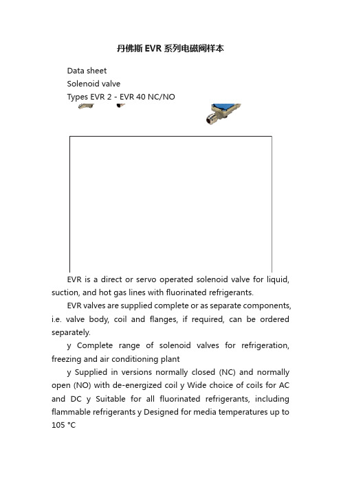
丹佛斯EVR系列电磁阀样本Data sheetSolenoid valveTypes EVR 2 - EVR 40 NC/NOEVR is a direct or servo operated solenoid valve for liquid, suction, and hot gas lines with fluorinated refrigerants.EVR valves are supplied complete or as separate components, i.e. valve body, coil and flanges, if required, can be ordered separately.y Complete range of solenoid valves for refrigeration, freezing and air conditioning planty Supplied in versions normally closed (NC) and normally open (NO) with de-energized coil y Wide choice of coils for AC and DC y Suitable for all fluorinated refrigerants, including flammable refrigerants y Designed for media temperatures up to 105 °Cy MOPD up to 25 bar with 12 W coil y Flare connections up to 5/8 in y Solder connections up to 2 1/8 iny Extended ends on solder versions make the installation easy. It is not necessary to dismantle the valve when soldering in y Available in flare, solder and flange connection versions FeaturesDet norske Veritas, DNVPressure Equipment Directive (PED) 97/23/EC Low Voltage Directive (LVD) 2006/95/ECPolski Rejestr Statków, Polen Maritime Register of Shipping, MRS Versions with UL approval can be supplied to order.ApprovalsData sheet Solenoid valve, types EVR 2 ? EVR 40 NC/NOTechnical data1) MOPD (Max. Opening Pressure Differential) for media in gas form is approx. 1 bar greater.2)Min. diff. pressure 0.07 bar is needed to stay open.RefrigerantsR22/R407C, R404A/R507, R410A, R134a, R407A, R23, R32, R290, R600, and R600a. For other refrigerants, contact Danfoss.Special note for R32, R290, R600, and R600a : Use only for system in compliance withstandard EN13463-1. Ignition risk is evaluated inaccordance with standard EN13463-1.Only EVR 2 - EVR 20 with solder connections andwithout manual stem can be applied in systemswith R32, R290, R600, and R600a as the workingfluid. For countries where safety standards are not an indispensable part of the safety system Danfoss recommends the installer to seek third partyapproval for systems containing R32, R290, R600, Note, please follow specific selection criteria stated in the datasheet for these particular refrigerants.Temperature of medium-40 –105 °C with 10 W or 12 W coil.Max. 130 °C during defrosting.Ambient temperature and enclosure for coil See separate data sheet for coils and ATEX coils.Capacity The capacity of the valve depends on the flow direction, see K v values from the table.The K v value is the water flow in [m 3/h] at a pressure drop across valve of 1 bar, ρ = 1000 kg/m 3.See extended capacity tables later in this datasheet.Table of contentsTechnical data...................................................................................................................... .......................................................2Rated capacity [kW] .................................................................................................................................................................3Ordering .............................................................. .........................................................................................................................4C apacity,Liquid .................................................................................................................. .......................................................7Capacity,Suction ............................................................................................................... ......................................................11Capacity, Hot gas ....................................................................................................................... .............................................19Design .............................................................. .. (40)Function.............................................................................................................. .......................................................................42Material specifications ................................................................................................... ......................................................43Dimensions and weights .. (45) Data sheet Solenoid valve, types EVR 2 ? EVR 40 NC/NORated liquid and suction vapour capacity is based on evaporating temperature t e = -10 °C, liquid temperature ahead of valve t l = 25 °C, pr essure drop in valve ?p = 0.15 bar.Rated hot gas capacity is based on condensing temperature t c = 40 °C, pressure drop across valve ?p = 0.8 bar, hot gas temperature t h = 65 °C,and subcooling of refrigerant ?tsub = 4 K.Rated capacity [kW]Data sheet Solenoid valve, types EVR 2 ? EVR 40 NC/NOOrdering (continued)EVR solder connections, Normally Closed (NC) - separate valve bodiesData sheet Solenoid valve, types EVR 2 ? EVR 40 NC/NOThe normal range of coils can be used for the NO valves, with the exception of the double frequency versions of 110 V, 50/60 Hz and 220 V, 50/60 Hz.Ordering (continued)EVR solder connections, Normally Open (NO) - separate valve bodiesValve bodies are supplied without flare nuts. Separate flare nuts:– 1/4 in or 6 mm, code no. 011L1101 – 3/8 in or 10 mm, code no. 011L1135 – 1/2 in or 12 mm, code no. 011L1103 – 5/8 in or 16 mm, code no. 011L1167OrderingEVR flare connections, Normally Closed (NC) - separate valve bodiesSee separate data sheet for coils.The normal range of coils can be used for the NO valves, with the exception of the double frequency versions of 110 V, 50/60 Hz and 220 V, 50/60 Hz.Data sheet Solenoid valve, types EVR 2 ? EVR 40 NC/NO Ordering (continued)Separate valve bodies, normally closed (NC)See separate data sheet for coils.Flange setsAccessoriesEVR 15 without manual operation, code no. 032F1224? in weld flange set, code no. 027N1115+ coil with terminal box, 220 V, 50 Hz, code no. 018F6701See separate data sheet for coils.ExampleCapacities are based on:– liquid temperaturet l = 25 °C ahead of valve, – evaporating temperature t e = -10 °C, superheat 0 K.Correction factorsWhen sizing valves, the plant capacity must be multiplied by a correction factor depending on liquid temperature t l ahead of valve/evaporator.When the corrected capacity is known,the selection can be made from the table.R22/R407CCorrection factors based on liquid temperature t lLiquidCapacities are based on:– liquid temperaturet l = 25 °C ahead of valve, – evaporating temperature t e = -10 °C, superheat 0 K.Correction factorsWhen sizing valves, the plant capacity must be multiplied by a correction factor depending on liquid temperature t l ahead ofWhen the corrected capacity is known,the selection can be made from the table.Correction factors based on liquid temperature t lR404A/R507Liquid (continued)Capacities are based on:– liquid temperaturet l = 25 °C ahead of valve, – evaporating temperature t e = -10 °C, superheat 0 K.Correction factorsWhen sizing valves, the plant capacity must be multiplied by a correction factor depending on liquid temperature t l ahead ofWhen the corrected capacity is known,the selection can be made from the table. Correction factors based on liquid temperature t lR290Liquid (continued)Data sheet Solenoid valve, types EVR 2 ? EVR 40 NC/NOCapacities are based on:– liquid temperaturet l = 25 °C ahead of valve, – evaporating temperature t e = -10 °C, superheat 0 K.Correction factorsWhen sizing valves, the plant capacity must be multiplied by a correction factor depending on liquid temperature t l ahead of valve/evaporator.When the corrected capacity is known,the selection can be made from the table.Correction factors based on liquid temperature t lR600Capacity Liquid (continued)Data sheetSolenoid valve, types EVR 2 ? EVR 40 NC/NOR22/R407CCorrection factorsWhen sizing valves, the evaporator capacity must be multiplied by a correction factor depending on liquid temperature t l ahead of expansion valve.When the corrected capacity is known, the selection can be made from the table.Correction factors for evaporating temperature tlCapacities are based on liquid temperature t l = 25 °C ahead of evaporator. The table values refer to the evaporator capacity and are given as a function ofevaporating temperature t e and pressure drop ?p across valve.Capacities are based on dry, saturated vapour ahead of valve.During operation with superheated vapour ahead of valve, the capacities are reduced by 4% for each 10 K superheat.Capacity SuctionData sheet Solenoid valve, types EVR 2 ? EVR 40 NC/NOCapacities are based on liquid temperature t l = 25 °C ahead of evaporator. The table values refer to the evaporator capacity and are given as a function ofevaporating temperature t e and pressure drop ?p across valve.Capacities are based on dry, saturated vapour ahead of valve.During operation with superheated vapour ahead of valve, the capacities are reduced by 4% for each 10 K superheat.Correction factors based on evaporating temperature t lCorrection factorsWhen sizing valves, the evaporator capacity must be multiplied by a correction factor depending on liquid temperature t l ahead of expansion valve.When the corrected capacity is known,the selection can be made from the table.R134aCapacity Suction(continued)Data sheet Solenoid valve, types EVR 2 ? EVR 40 NC/NOCorrection factors based on evaporating temperature t lCorrection factors When sizing valves, the evaporator capacity must be multiplied by a correction factor depending on liquid temperature t l ahead of expansion valve.When the corrected capacity is known,the selection can be made from the table.R404A/R507Capacities are based on liquid temperature t l = 25 °C ahead of evaporator. The table values refer to the evaporator capacity and are given as a function ofevaporating temperature t e and pressure drop ?p across valve.Capacities are based on dry, saturated vapour ahead of valve.During operation with superheated vapour ahead of valve, the capacities are reduced by 4% for each 10 K superheat.Capacity Suction(continued)Data sheet Solenoid valve, types EVR 2 ? EVR 40 NC/NOCorrection factors based on evaporating temperature t lCorrection factorsWhen sizing valves, the evaporator capacity must be multiplied by a correction factor depending on liquid temperature t l ahead of expansion valve.When the corrected capacity is known,the selection can be made from the table.R32Capacities are based on liquid temperature t l = 25 °C ahead of evaporator. The table values refer to the evaporator capacity and are given as a function ofevaporating temperature t e and pressure drop ?p across valve.Capacities are based on dry, saturated vapour ahead of valve.During operation with superheated vapour ahead of valve, the capacities are reduced by 4% for each 10 K superheat.Capacity Suction(continued)Data sheet Solenoid valve, types EVR 2 ? EVR 40 NC/NOCorrection factors based on evaporating temperature t lCorrection factorsWhen sizing valves, the evaporator capacity must be multiplied by a correction factor depending on liquid temperature t l ahead of expansion valve.When the corrected capacity is known,the selection can be made from the table.R290Capacities are based on liquid temperature t l = 25 °C ahead of evaporator. The table values refer to the evaporator capacity and are given as a function ofevaporating temperature t e and pressure drop ?p across valve.Capacities are based on dry, saturated vapour ahead of valve.During operation with superheated vapour ahead of valve,the capacities are reduced by 4% for each 10 K superheat.Capacity Suction(continued)Data sheet Solenoid valve, types EVR 2 ? EVR 40 NC/NOCorrection factors based on evaporating temperature t lCorrection factorsWhen sizing valves, the evaporator capacity must be multiplied by a correction factor depending on liquid temperature t l ahead of expansion valve.When the corrected capacity is known,the selection can be made from the table.R600Capacities are based on liquid temperature t l = 25 °C ahead of evaporator. The table values refer to the evaporator capacity and are given as a function ofevaporating temperature t e and pressure drop ?p across valve.Capacities are based on dry, saturated vapour ahead of valve.During operation with superheated vapour ahead of valve, the capacities are reduced by 4% for each 10 K superheat.Capacity Suction(continued)Data sheet Solenoid valve, types EVR 2 ? EVR 40 NC/NOCorrection factors based on evaporating temperature t lCorrection factorsWhen sizing valves, the evaporator capacity must be multiplied by a correction factor depending on liquid temperature t l ahead of expansion valve.When the corrected capacity is known,the selection can be made from the table.R600aCapacities are based on liquid temperature t l = 25 °C ahead of evaporator. The table values refer to the evaporator capacity and are given as a function ofevaporating temperature t e and pressure drop ?p across valve.Capacities are based on dry, saturated vapour ahead of valve.During operation with superheated vapour ahead of valve, the capacities are reduced by 4% for each 10 K superheat.Capacity Suction(continued)Data sheet Solenoid valve, types EVR 2 ? EVR 40 NC/NO Hot gas defrostingWith hot gas defrosting it is not normally possible to select a valve from condensing temperature t c and evaporating temperature t e .This is because the pressure in the evaporator as a rule quickly rises to a value near that of the condensing pressure. It remains at this value until the defrosting is finished.In most cases therefore, the valve will be selected from condensing temperature t c and pressure drop ?p across the valve, as shown in the example for heat recovery.Heat recovery The following is given: y Refrigerant = R22/R407Cy Evaporating temperature t e = -30 °C y Condensingtemperature t c = 40 °Cy Hot gas temperature ahead of valve t h = 85 °Cy Heat recovery condenser yield Q h = 8 kWThe capacity table for R22/R407C with t c = 40 °C gives the capacity for an EVR 10 as 8.9 kW, when pressure drop ?p is 0.2 bar.The required capacity is calculated as :Q table = f evaporator x f hot_temperature x Q hThe correction factor for t e = -30 °C is given in the table as 0.95.The correction for hot gas temperature t h = 85 °C has been calculated as 4% which corresponds to a factor of 1.04.Q h must be corrected with factors found: With ?p = 0.2 baris Q h = 8.71 x 0.95 x 1.04 = 8.6 kW.With ?p = 0.1 bar, Q h becomes only 6.19 x 0.95 x 1.04 = 6.1 kW.An EVR 6 would also be able to give the required capacity, but with ?p at approx. 1 bar. The EVR 6 is therefore too small.The EVR 15 is so large that it is doubtful whether the necessary ?p of approx. 0.1 bar could be obtained.An EVR 15 would therefore be too large.Result: An EVR 10 is the correct valve for the given conditions.Capacity Suction (continued)Data sheetSolenoid valve, types EVR 2 ? EVR 40 NC/NOR22/R407CAn increase in hot gas temperature t h of 10 K, based on t h = t c +25 °C, reduces valve capacity approx. 2% and vice versa.A change in evaporating temperature t e changes valve capacity; see correction factor table below.Correction factorsWhen sizing valves, the table value mustbe multiplied by a correction factor depending on evaporating temperature t e .Correction factors for evaporating temperature teCapacity Hot gas。
VICKERS电磁阀威格士电磁阀样本

VICKERS电磁阀/威格士电磁阀样本美国威格士原装正品,假一罚十,可以提供报关证明和原产地证明等文件。
美國威格士VICKERS比例压力溢流阀工作时,是利用弹簧的压力来调节、控制液压油的压力大小。
从图3-50中可以看到:当液压油的压力小于工作需要压力时,阀芯被弹簧压在液压油的流入口,当液压油的压力超过其工作允许压力即大于弹簧压力时,阀芯被液压油顶起,液压油流入,从图示方向右侧口流出,回油箱。
液压油的压力越大,阀芯被液压油顶起得越髙,液压油经溢流阀流回油箱的流量越大o如过液压油的压力小于或等于弹簧压力,则阀芯落下,封住液压油进口。
由于油泵输出的液压油压力固定,而工作油缸用液压油的压力总要比油泵输出液压油压力小,所以正常工作时总会有一些液压油从溢流阀处流回油箱,以保持液压油缸的工作压力平衡、正常工作。
由此可见,直动式溢流阀的作用是能够防止液压系统中的液压油压力超出额定负荷,起安全保护作用。
VICKERS比例压力溢流阀和外装附件组成。
其中,主阀包括阀体、压板及膜片、大阀板、缓闭阀板、阀座、阀杆组件等部件。
缓闭阀板用阀杆组件与压板及膜片连接一起,膜片压紧在阀盖与膜片座之间,膜片的上下运动带动缓闭阀板上下升降。
阀杆穿过大阀板的中心孔,因之大阀板可以在一定的范围内沿阀杆滑动。
平时,大阀板在自重压紧在阀座上,使阀门处于关闭状态。
多功能水泵控制阀的外装附件安装在阀门膜片两侧与阀门进、出水管上,膜片的下腔与阀门进水侧的连接管上装设控制阀、过滤器和一只特制的逆止阀。
膜片的上腔与阀门的出水侧的连接管上只设过滤器和一只控制阀。
主阀内大阀板和缓闭阀板的运动和所处的位置决定了阀门工作状态的变化和启闭。
VICKERS电磁阀/威格士电磁阀样本VICKERS电磁阀的主阀按配合形式不同可分为三级同心、二级同心和滑阀式三类。
其中滑阀式结构工作压力低,控制压力精度不高;三级同心结构虽成熟,目前应用较广,但与二级同心式比较,不及二级同心式动作灵敏,规格相同,行程相同时,二级同心结构的通油能力远大于三级同心结构;二级同心式控制压力稳定,加工工艺性好,二级同心式应用前景广阔,这里以二级同心结构,讨论其结构尺寸设计方法。
电磁阀(burert)样本

2/2-way servo assisted Solenoid Valve for liquidsThe Type 6213 is a 2/2-way normally closed solenoid valve with a forced coupled diaphragm system. It switches from 0 bar and can be used universally for fl uids. For complete opening, a differential pressure of at least 0.1 bar is necessary.Cable plugTimer unitCircuit function AServo-assisted 2/2-way valve; normally closed, with 2-way pilot control1)Measured at valve outlet at 6 bar and +20°C Opening: pressure build-up 0 to 90% Closing : pressure decay 100 to 10%Technical dataPower consumption1) Values in brackets at coil temperature 20 ºC MaterialsOrdering chart for valves (other versions on request) Valves with brass or stainless steel body, without cable plug1) Measured at +20ºC, 1 bar 2) pressure at valve inlet and free outlet2) Pressure data [bar]: Overpressure with respect to atmospheric pressure.Please note that the cable plug has to be ordered separately, see Ordering chart for accessory and separate datasheet, Type 2508* For DN 25 and DN 40 with 24 V/UC, a cable plug with an integrated high-power electronics is provided as part of the delivery. Further versions on requestPort connectionDN 10 G 1/2, 13 G 3/4, 20 G 1, NPT, RcTemperatureFKM version up to +120ºC with Epoxy coilVoltageNon-standard voltagesApprovalsUL, UR, CSASeal MaterialEPDM with KTW/FDA approvalOrdering chart for accessoryThe delivery of a cable plug includes the fl at seal and the fi xing screw. For other cable plug versions acc. to DIN EN 175301-803 Form A (previouslyDIN 43650), see separate datasheet Type 2508.Flat sealFixing screwDimensions [mm]G Thread AC coil DC coil DC and AC coil G F B H K B H K C G 1/41282.0324582.5405137.5G 3/812G 1/214G 1/21495.5324596.0405145.0G 3/416G 3/416115.53245116.0405166.0G 118To fi nd your nearest Bürkert facility, click on the orange box In case of special application conditions, please consult for advice.Subject to alterations© Christian Bürkert GmbH & Co. KG0810/4_EU-en_00891750Dimensions [mm]。
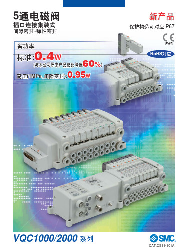
SMC电磁阀样本
4
2
(A)
(B)
5
3
(R1)
1 (R2)
(P)
特长 2
底板配管型:扩展品种
/
声速 流导 C[dm3/(s·bar)] CYL→EXH 4/2→5/3 的值
单3 电位 控阀 双中 电封 控式
)
(
S组件
串行传送
对应网关
对应网络
• DeviceNet™
对应网络
对应网络
对应网络
• PROFIBUS DP • DeviceNet™
对应输入输出
EX500series
串行单元:
EX500
对应IP67
串行单元 (现场总线元件):
EX600
对应IP67
串行单元:
EX250
对应IP67
串行单元:
EX126
对应IP67
间
隙 密
VQC1□00
0.72
0.72
封
VQC1000
~ø50
系列
第5页
弹
性 密
VQC1□01
1.0
0.65
封
●
●
●
●
间
EX5se0ri0es
25针
26针
保护构造
20针
可对应IP67
保护构造 可对应IP67
● 为了配线作业及维护容易,6种方式已标准化,4种方式的保护构造对应IP67。 ● 对S组件,有输入输出形式。(网关单元除外)
25心电缆
保护构造 可对应IP67
26针
保护构造 可对应IP67
插口连接集装式
● 集装块内的配线上,采用插口连接方式,故增位及规格变更
FESTO电磁阀选型样本

电磁阀
VUVY-F - L -
管式阀
两位五通单电控 两位五通双电控 三位五通双电控
两位五通阀 三位五通阀 , 三位五通阀 , 三位五通阀源自,中封式 中压式 中泄式
气复位(仅用于 5/2单电控) 弹簧复位
手动操作不带锁定(标准配置)
Gx G?
工作电压 1 2A 3A 5 线圈插座 C1
4 手动控制工具的位置
5 通孔 2- Φ4.4,可 安装螺钉 M4×37
1) 注:密封圈不能反向 !
2009/06 - 产品样本
电磁阀 VUVY-F
技术参数
订货数据 符号
说明
两位五通双电控
* 可根据客户要求订制,请联系当地 Festo公司。
接口尺寸 Gx
G?
电压 24V DC 110V AC* 230 V AC 12 V DC* 24 V DC 110 V AC* 230 V AC 12 V DC*
2009/06 - 产品样本
电磁阀 VUVY-F
技术参数 - 两位五通单电控阀
尺寸 管式安装、气路板安装 , 接口螺纹 G?
1 电磁线圈可以转动 180°1) 2 手控装置
3 插头符合 EN 175 301-803标准 C型, 插座型号:MSSD-E或B KMEB…-
4 手动控制工具的位置
5 通孔 2- Φ4.4,可 安装螺钉 M4×37
545433
VUVY-F-L-P53E-H -G14-1C1
545434 VUVY-F-L-P53E-H
-G14-2AC1
545435
VUVY-F-L-P53E-H -G14-3AC1
545436 VUVY-F-L-P53E-H
- 1、下载文档前请自行甄别文档内容的完整性,平台不提供额外的编辑、内容补充、找答案等附加服务。
- 2、"仅部分预览"的文档,不可在线预览部分如存在完整性等问题,可反馈申请退款(可完整预览的文档不适用该条件!)。
- 3、如文档侵犯您的权益,请联系客服反馈,我们会尽快为您处理(人工客服工作时间:9:00-18:30)。
方向控制阀
CETOP 3 规格 柔合换向
方向控制阀
DG4V-3(S)-60 设计
Revised 6/93
614-C
目录表
DG 4V-3(S ) 型号编法 . . . . . . . . . . . . . . . . . . . . . . . . . . . . . . . . . . . . . . . . . . . . . . . . . . . . . . . . . . . . . . . . . . . . . . . . . . . . . . . . . . . . . . . . . . 4 DG 4V-3(S ) 工作数据 . . . . . . . . . . . . . . . . . . . . . . . . . . . . . . . . . . . . . . . . . . . . . . . . . . . . . . . . . . . . . . . . . . . . . . . . . . . . . . . . . . . . . . . . . . 5
* 推荐用于高性能“8C ”型阀芯的最小节流孔规格。
13 电气连接 (仅“F ”型线圈,如果不需要,省 略)
PA – 仅 Ins ta 插头仅阳插座 PA3 – 3 针插座 PA5 – 5 针插座 P B – Ins ta 插头阳和阴插座 T 线圈,如果不需要,省 略)
5 阀芯/弹簧配置 A – 弹簧偏置,单电磁铁 AL – 弹簧偏置,单电磁铁
(左手配置) B – 弹簧对中,单电磁铁 B L – 弹簧对中,单电磁铁
(左手配置) C – 弹簧对中
6 柔合换向阀
9 电磁铁通电标识 空白 – ANS I B 93 电磁铁 A 通电,
流量从 P 到 A V – 电磁铁识别取决于电磁铁的
W – 1/2” NP T J – M20 x 1.5 - 6H G – G 1/2
15 电磁铁指示灯 (P A, U, S P 1, S P 2 不适用,如果 不需要,省略)
16 线圈识别字母
GH – 12V DC DTH– 18V DC HH – 24V DC DJ H – 98V DC (P 12L 型需要) P H – 110V DC S H – 220V DC
正确的油液状态对于液压元件和系统的 长而满足的寿命来说至关重要。液压油 必须具有清洁度、材料和添加剂(用于 保护元件免遭磨损,提高粘度和清除空 气)之间的正确平衡。
有关处理压油液的正确方法的基本资料 见威格士出版物 561“威格士系统污染 控制指南”,可从您就近的威格士销售 机构或代理商处获得。 561 中包括过滤 建议和控制油液状态的产品的选择。
12 线圈插头 ( 仅“U ”型线圈,如果不需要,省略 ) 1 – 配好插头 6 – 配好带灯的插头 11 – 配好带灯的整流器 12 – 配好整流器
7 柔合换向节流孔规格
00 – 无节流孔 07 – 0.7 mm 直径 08 – 0.8 mm 直径 09 – 0.9 mm 直径 20 – 2.0 mm 直径*
系统压力
1000 ps i 2000 ps i 3000+ ps i
阀
20/18/15 20/18/15 19/17/14
功能符号
标准阀 芯型式
图形符号 中位条件
0
3
2 6
8
31 33
弹簧偏置
b
AB
P -T
弹簧对中
b
AB
a
-P T
b
AB
a
-P T
b
AB
a
-P T
b
AB
a
-P T
b
AB
a
-P T
b
AB
位置(即电磁铁 A 在阀的 A 口 端,电磁铁 B 在阀的 B 口端)
10 标记符号 (介绍电气特性和选项)
11 线圈型式 F – 飞线类线圈 U – DIN 43650 线圈 S P 1 – 单1/4” 扁插头 S P 2 – 双 1/4” 扁插头 P 12L – 插装式线圈,带包括整流器
和灯的接线盒 K U – 顶部出口飞线
17 油箱压力额定值
2 – 10 bar (145 ps i) 5 – 100 bar (1450 ps i) 用于 DG 4V -3S 7 – 207 bar (3000 ps i) 用于 DG 4V -3
18 设计号
19 油口节流孔
空白 – 00 03 - 0.3 mm 直径 06 - 0.6 mm 直径 08 - 0.8 mm 直径 10 - 1.0 mm 直径 13 - 1.3 mm 直径 15 - 1.5 mm 直径 20 - 2.0 mm 直径 23 - 2.3 mm 直径 (例: “P 03” = 0.3 mm 直径节流孔在 阀的 P 口。如果不需要,省略)
●内泄少,功耗少,系统效率高,改善 了阀芯和阀孔的制造。
●具有多种电磁铁插头和位置的组合供 选择,安装灵活。
●适用于多种油液,无需更换密封件。
●超过 2000 万次循环试验已证实其优 秀的疲劳寿命和持久寿命,使得机器 长期生产率高,开工时间更长。
●可以迅速而方便地更换电磁铁线圈而 不引起液压系统漏油。
在普通条件下,使用石油基油液时推荐 的清洁度等级是基于系统中的最高油液 压力等级。
方向控制阀(无论哪家制造的)将能在 更高清洁度代号的油液中工作。但是方 向阀和系统中的其他元件的工作寿命要 缩短,为了最长的工作寿命和最佳的性 能,下面规定的清洁度代号应当达到。
非石油基的其他油液、重载工作循环或 极端温度是调整这些清洁度代号的理由。 准确的细节见威格士出版物 561。
4
DG 4V -3S -60 工作数据
基本特性
最高压力,油口 P, A 和 B : . . . . . . . . . . . . . . . 350 bar (5075 ps i) 最高压力,油口 T : 3S . . . . . . . . . . . . 100 bar (1450 ps i) 3 . . . . . . . . . . . . . 207 bar (3000 ps i) 最大流量:3S . . 达 40 l/min
8 手动操作
空白 – 仅在电磁铁端操作 P 2 – 手动操作在端盖和电磁铁上,
仅A和B 型
2 接口 3 – IS O 4401-03, C E TOP 3 (NFPA D03)
3 阀性能 S - 标准性能 空白 - 高性能
4 阀芯型式 0 – 开式中位 2 – 闭式中位 (全部油口) 3 – P 和 B 关闭,A 至 T 6 – 闭式中位 (仅 P ) 8 – 旁通中位 (过渡打开) 31 – P 和 A 关闭,B 至 T 33 – 闭式中位 (A 和 B 到 T )
基本特性 安装接口 功能符号 密封件和油液清洁度 电磁铁通电 . . . . . . . . . . . . . . . . . . . . . . . . . . . . . . . . . . . . . . . . . . . . . . . . . . . . . . . . . . . . . . . . . . . . . . . . . . . . . . . . . . . . . . . . . . . . . . . . 6 放气程序 技术规格 阀口节流器堵头 响应时间 . . . . . . . . . . . . . . . . . . . . . . . . . . . . . . . . . . . . . . . . . . . . . . . . . . . . . . . . . . . . . . . . . . . . . . . . . . . . . . . . . . . . . . . . . . . . . . . . . . 7 更换节流孔的程序 性能数据 . . . . . . . . . . . . . . . . . . . . . . . . . . . . . . . . . . . . . . . . . . . . . . . . . . . . . . . . . . . . . . . . . . . . . . . . . . . . . . . . . . . . . . . . . . . . . . . . . . . . . 8 压降 最大流量数据 . . . . . . . . . . . . . . . . . . . . . . . . . . . . . . . . . . . . . . . . . . . . . . . . . . . . . . . . . . . . . . . . . . . . . . . . . . . . . . . . . . . . . . . . . . . . . . 9 安装尺寸 . . . . . . . . . . . . . . . . . . . . . . . . . . . . . . . . . . . . . . . . . . . . . . . . . . . . . . . . . . . . . . . . . . . . . . . . . . . . . . . . . . . . . . . . . . . . . . . . . . . . 10 电气插头 . . . . . . . . . . . . . . . . . . . . . . . . . . . . . . . . . . . . . . . . . . . . . . . . . . . . . . . . . . . . . . . . . . . . . . . . . . . . . . . . . . . . . . . . . . . . . . . . . . . . 12 安装接口 . . . . . . . . . . . . . . . . . . . . . . . . . . . . . . . . . . . . . . . . . . . . . . . . . . . . . . . . . . . . . . . . . . . . . . . . . . . . . . . . . . . . . . . . . . . . . . . . . . . . 13