3124中文说明书
bosch rexroth 4 3-4 2 直流电磁阀 手册说明书

4/3 - 4/2 Directional valves L50A0… (LC04-A)Replaces: 07.12 solenoid operatedRE 18305-11Edition: 06.2022▶Size 4▶Series 00▶Maximum operating pressure 310 bar (4500 psi)▶Maximum fl ow 25 l/min (6.6 gpm)ContentsOrdering details 2Functional description 4Technical data 5Characteristic curves 7External dimensions and fi ttings 8Electric connection 9 L50A0… (LC04-A)General specifi cations▶Direct solenoid operated spool valve, standard version.▶Spool switching is by on off solenoids with a centraltube and removable coil.▶Spring centered control spool.▶For mounting on industry standard surfaceport pattern to CETOP RP121 H-4.2-P02.▶Wet pin DC solenoids with removable coil and manualoverride.▶Manual override as option (push or screw-in type).▶Coil can be rotated through 360°.▶Available electrical connections: DIN 43650 – ISO 4400,AMP JUNIOR, DT04-2P (Deutsch), Free leads.RE 18305-11/06.2022,2L50A0… (LC04-A) | 4/3 - 4/2 Directional valves Ordering detailsOrdering details0102030405060708 L50A0Family01Directional Valves L Type02CETOP Valves5 Size03NG 4 (P02)0 Operation04Solenoid operated D36 coil A0 Spool variants054/3 operated A and B side_ 2 _ _ 4/2 operated A and B side_ 2 _ _ 4/2 operated A side_ 3 _ _ 4/2 operated B side_ 4 _ _ 4/2 operated A and B side with detent_ 5 _ _ Voltage supply31070403010006Without coil–––––●0012 V DC●●●●●–OB24 V DC●●●●●–OC48 V DC–●●●●–OD96 V DC––––●–OU205 V DC––––●–AH Electric connections07Without coils00 With coils, without mating connector011) DIN EN 175301-803With coils, with bi-directional diode, without mating03 connector vertical Amp-JuniorWith coils, with bi-directional diode, without mating04 connector horizontal Amp-JuniorWith coils, with bi-directional diode, without mating07 connector DT04-2PWith coils and bipolar sheathed lead31 300mm (11,8 in) longOptions08Standard00 External push button manual override EPScrew-in type manual override EF●=Available–=Not available1) For connectors ordering code see data sheet RE 18325-90., RE 18305-11/06.2022RE 18305-11/06.2022, 4/3 - 4/2 Directional valves | L50A0… (LC04-A)Ordering details3Spool variants=A201=C201=E201AB_ 2 _ _P T ababAB_ 2 _ _P T ababAB_ 3 _ _P T aaAB_ 4 _ _P T 0bbAB_ 5 _ _P Tabab=G209=K209=L201=N201=L501=N501=A301=B301=C301=D301=E301=K301=T301=Y301=A401=B401=C401=D401=E401=K401=T409=Y401=B201=D201=G201=K201=M201=M501=A361=B361=C361=D361=E361=N301=X301=A471=B471=C471=D471=E471=N401=X4014L50A0… (LC04-A) | 4/3 - 4/2 Directional valves Functional descriptionFunctional descriptionType L50A0The solenoid operated valves type L 50A0 provide 3-way or 4-way fl ow control, usually from port P to either port A or B, and the consequent fl ow return to T from B or A respectively.The valves are composed by a central cast iron body (1) which mounts on industry standard surfaces where thefl ow ports and the installation holes are located; the central body houses the precisely machined directional control spool (2) which is held in the neutral or initial position by the return springs (4). One or two solenoids, composed by a central tube and a surrounding coil (5), are fi tted to the body at the spool’s ends: when the coils are energized, their magnetic fi eld develops a force on the oil immersed mobile plunger incorporated in the tube which pushes the control spool from the initial position into a shifted position where oil fl ow is allowed from P to either A or B.With coils (5) de-energized, the control spool (2) returns to the central or initial position pushed by the washers (3) supported by the return springs (4).The coils (5) are locked on the tube by threaded plastic nuts (6); the tube incorporates an externally reachable push rod (7) which can pushed for emergency spool shifting in case of electric failure.Type L50A0L201_, L50A0M201_, L50A0N201_These valves do not have return springs (4) for the directional control spool (2): the spool can shift between two positions, driven only by the magnetic force developed by the two solenoids (5), and, when the solenoids are not energized, the neutral position of the spool is not defi ned. The directional control spool holds a specifi c position only when one of the solenoids is maintained energized.Type L50A0L501_, L50A0M501_, L50A0N501_In these valves the directional control spool has two switched positions, each one with a mechanical detent. Shifting of the spool’s position is achieved by energizing one of the solenoids, but it is unnecessary to maintain the coil energized in order to keep the spool shifted., RE 18305-11/06.20224/3 - 4/2 Directional valves| L50A0… (LC04-A)5Technical dataTechnical dataVoltage tolerance (nominal voltage)%-10 .... +10Duty Continuous, with ambient temperature ≤ 50°C (122°F)Coil wire temperature not to be exceeded°C (°F)180 (356)Insulation class HCompliance with Low Voltage Directive LVD 73/23/EC (2006/95/EC), 2004/108/EC Coil weight with connection EN 175301-803kg (lbs)0.18 (0.40)Voltage V12244896205 Voltage type DC DC DC DC DC Power consumption W2020202020 Current (nominal at 20 °C (68 °F))A 1.620.840.450.210.01 Resistance (nominal at 20 °C (68 °F))Ω7.428.4106.44512062NoteFor applications with diff erent specifi cations consult us.RE 18305-11/06.2022,6L50A0… (LC04-A) | 4/3 - 4/2 Directional valves Technical data(Ex. DIN 43650)NoteFor further versions (i.e. cable single lead) contact factory., RE 18305-11/06.2022RE 18305-11/06.2022, 4/3 - 4/2 Directional valves | L50A0… (LC04-A) Characteristic curves7Characteristic curvesMeasured with hydraulic fl uid ISO-VG32 at 45° ±5 °C (113° ±9 °F); ambient temperature 20 °C (68 °F).Performance limits5 1 4 3 2bar350300250200150100500 5 10 15 20 25l/min 0 1 2 3 4 5 6 6.6 gpmpsi 50004000300020001000P r e s s u r e pFlow QB201; B301; B401; B361; B471; C201; C301; C401; C361; C471; L201; L501; M201; M5012E201, E301, E401; E361; E471; D201, D301, D401; D361; D471; K201, K209; K301; K401; T301; T4093X301; X401; Y301; Y4014N201; N301; N401; N5015The performance curves here shown are applicable when oil fl ow is travelling in both directions, example P>A and B>T. In special circuit schemes the performance limits can be lower.G201, G209B201, B301, B401 5577B361, B4715588C201, C301, C401, C361, C471, D201, D301, D401; D361, D47166688E201, E301, E401, E361, E471, K201, K209, K301, K4015588L2015587L5013577M2013376M5012365N20133N30125N40152N50123T301, T40955X301, Y3013586X401, Y4015368P r e s s u r e Δp1 2 3 4 5 6 7 80 5 10 15 20 25 l/min bar 2016128400 1 2 3 4 5 6 6.6 gpmpsi 290250200150100500Flow Q8L50A0… (LC04-A) | 4/3 - 4/2 Directional valvesExternal dimensions and fi ttingsDimensions [mm (inches)] External dimensions and fittings1 Solenoid tube O 16mm (0.63inch).2 Blinding plug for 2 positions version.3 Ring nut for coil locking O 26,5 mm (1,04inch).Torque 3 – 4 Nm (2.2 – 3.0 ft-lb).4 Drilling specifi cations of standard mounting surface according toCETOP RP 121 H-4.2 4-P02.5 Locking screws 3 pieces: UNI 5931 (ISO 4762) hexagon sockethead cap screw M 5x25, recommended specifi c strength 8.8class. Torque 5 ÷ 6 Nm (3.7÷4.4 ft-lbs).6 Gap needed for connector removal.7 Optional push-button type manual override for spool opening:it is pressure stuck to the ring nut for coil locking.Mat no. R930059524.8 Optional screw type manual override for spool opening: it isscrewed torque 6-7Nm (4.4-5.2 ft-lb) to the tube as replacement of the coil ring nut. Mat no. R930059561.9 Identifi cation label., RE 18305-11/06.2022RE 18305-11/06.2022, 4/3 - 4/2 Directional valves | L50A0… (LC04-A)Electric connection9Dimensions [mm (inches)]E lectric connection 0001()()()()()()03Protection class: IP 65 with female connectorproperly fi tted (see drawing).04Protection class: IP 65 with female connectorproperly fi tted (see drawing).()()()()()()()()()()()()()3107Protection class: IP 69 K with female connector properly fi tted (see drawing).()()()()()()()()()()()()()()10, RE 18305-11/06.2022Bosch Rexroth Oil Control S.p.A.Oleodinamica LC Division Via Artigianale Sedrio, 1242030 Vezzano sul Crostolo Reggio Emilia - Italy Tel. +39 0522 601 801Fax +39 0522 606 226 / 601 802***************************************/compacthydraulics© This document, as well as the data, specifi cations and other information set forth in it, are the exclusive property of Bosch Rexroth Oil Control S.p.a.. It may not be reproduced or given to third parties without its consent.The data specifi ed above only serve to describe the product. No statements concerning a certain condition or suitability for a certain application can be derived from our information. The information given does not release the user from the obligation of own judgment and verifi cation. It must beremembered that our products are subject to a natural process of wear and aging.Subject to change.。
HIRSCHMANN交换机说明书(中文)
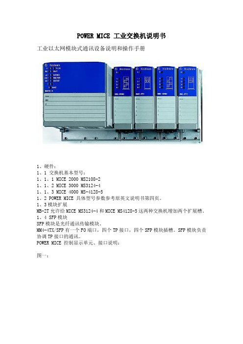
POWER MICE 工业交换机说明书工业以太网模块式通讯设备说明和操作手册1、硬件:1、1 交换机基本型号:1、1、1 MICE 2000 MS2108-21、1、2 MICE 3000 MS3124-41、1、3 MICE 4000 MS-4128-51、2 POWER MICE 具体型号参数参考原英文说明书第四页。
1、3模块扩展MB-2T允许给MICE MS3124-4和MICE MS4128-5这两种交换机增加两个扩展槽。
1、4 SFP模块SFP模块是光纤通讯传输模块。
MM4-4TX/SFP有一个FO端口,四个TP接口,四个SFP模块插槽。
SFP模块负责协调TP接口的通讯。
POWER MICE 控制显示单元、接口说明:图一:2、功能说明POWER MICE 提供的终端接口可以与LAN 网络连接,可以连接到单个的设备,也可以连接到相对完善的网络。
2、1交换机框架的功能保存和转寄多地址兼容识别地址静态地址输入RSTP优先权设置标记符定义(IEEE802.1Q)数据流量控制通讯端口监视2、2 TP/TX接口的专用功能连接控制:自动极性交换自动操作模式选择自动端口设置2、3 FO接口的专用功能连接控制:2、4 热备用功能2、5 安全2、6 AUI收发器专用功能2、7 更多的功能和技术参数2、7、1 诊断在复位时有硬件自检功能,在启动过程中内部有看门狗监视功能。
2、7、2 复位下列行为可以使MICE交换机复位:管理操作输入电压下降到允许极限看门狗动作内部时钟故障复位以后将运行下面的程序:自检初始化2、8 显示单元提供正常的工作电压以后,软件开始启动,MICE 将完成自检,处理过程中LED灯将闪烁,处理过程将持续60秒。
2、8、1 设备状态指示:P---电源指示(绿色),亮,表示正常,不亮,表示电压低;P1---电源1(绿色),亮,表示电源1正常,不亮,表示电源1低于18V;P2---电源2(绿色),亮,表示电源2正常,不亮,表示电源2低于18V;2、8、2 MICE MS2108-2和MS3124-4:故障---故障指示(红灯)红灯亮,表示信号开路或者连接错误;不亮,表示正常。
日本共立3124说明书
3124高压兆欧表使用说明书目录1.安全上的警告2.特点3.规格4.仪器面板5.测试前的准备6.操作须知7.电池充电8.更换电池9.镍镉电池的储藏10.记录器的连接1.安全上的警告z本操作手册包含了警告讯息及安全规定,当使用本机时请确实遵守,以确保使用者的操作安全及仪器安全,因此于使用本机前请先仔细地彻底的阅读本手册。
z本手册中表示.符号,提醒读者必须参考手册中的相关章节,确保操作安全。
z请特别注意本手册中WARNINGS及CAUTIONS的提示,WARNINGS表示要小心触电的危险而CAUTION表示须注意仪器的损坏。
z绝缘测试是用来测试已断电的电路(死线)或装置,请不要在有电的情况下(活线)做测试。
z在每次测试时请切记待测电路或装置必须是不带电的,请确认您可以清楚的看到待测电路或装置已与电力系统切离,,在作绝缘测试前,在尚未确认是否带电时请勿做任何测试。
z如果您不知道如何开始特高阻测试(高压)请先与待测设备的制造商讨论,有些设备装置了高敏度的电子元件,可能在高直流的电压下造成损坏,原制造商可事先对此提出警告避免此种损坏。
z本测试器能产生10KV的直流高电压,于测试时请不要接触测试导线或被测设备.请不要尝试用本机器去刺激或惊吓别人.潮湿的环境,流水的水笼都有可能造成触电而导致心脏停止。
z于测试时请不要打开电池盒盖。
z请时常注意您的仪器,测试导线以及其它附件是否有损坏的痕迹或变形,如果有任何异常发生(如:导线破损、机壳裂缝、显示屏幕无法读取等),请不要进行任何测试。
z在做测试的过程中请注意不要让自己成为接地的通路,不要接触外露的金属管,出水口、固定物等,它们可能会让您成为接地电位。
另外请将您的身体与大地隔绝,例如使用干布、绝缘鞋、绝缘毯或其它保证绝缘的物质。
z为避免触电事故,在工作电压高于40VDC或20V AC时请使用警告标志。
z在连接测试导线及探棒前请先确认功能选择钮是否位于OFF的位置,测试键并没有被压下或在锁定位置。
HMMC-3124资料

DC–12 GHz Packaged HighEfficiency Divide-by-4 PrescalerTechnical DataHMMC-3124 Features•Wide Frequency Range:0.2 - 12 GHz•High Input Power Sensitivity:On-chip pre- and post-amps-15 to +10 dBm (1 - 8 GHz)-10 to +8 dBm (8 - 10 GHz)-5 to +2 dBm (10 - 12 GHz)•P out: 0 dBm (0.5 V p-p)•Low Phase Noise:-153 dBc/Hz @ 100 kHz Offset •(+) or (-) Single Supply Bias Operation•Wide Bias Supply Range:4.5 to 6.5volt operating range •Differential I/0 with on-chip 50Ω matchingDescriptionThe HMMC-3124 is a packaged GaAs HBT MMIC prescaler which offers DC to 12 GHz frequency translation for use in communica-tions and EW systems incorporat-ing high-frequency PLL oscillator circuits and signal-path down conversion applications. The prescaler provides a large input power sensitivity window and low phase noise.Package Type:8-lead SSOP PlasticPackage Dimensions: 4.9 x 3.9 mm Typ.Package Thickness: 1.55 mm Typ.Lead Pitch: 1.25 mm Nom.Lead Width:0.42 mm Nom.Absolute Maximum Ratings[1](@ T A = 25°C, unless otherwise indicated)Symbol Parameters/Conditions Units Min.Max.V CC Bias Supply Voltage volts+7V EE Bias Supply Voltage volts-7|V CC - V EE|Bias Supply Delta volts+7V Logic Logic Threshold Voltage volts V CC-1.5V CC-1.2P in(CW)CW RF Input Power dBm+10 V RFin DC Input Voltage volts V CC±0.5 (@ RF in or RF in Ports)T BS[2]Backside Operating Temp.°C-40+85T STG Storage Temperature°C-65+165T max Maximum Assembly Temp.°C310(60 seconds max.)Notes:1.Operation in excess of any parameter limit (except T BS) may causepermanent damage to the device.2.MTTF >1 x10⁶ hours @ T BS < 85°C. Operation in excess of maximumoperating temperature (T BS) will degrade MTTF.HMMC-3124 DC Specifications/Physical Properties,(T A = 25°C, V CC - V EE = 5.0 V unless otherwise listed)Symbol Parameters and Test Conditions Units Min.Typ.Max.V CC - V EE Operating Bias Supply Difference [1]volts 4.5 5.0 6.5|I CC | or |I EE |Bias Supply CurrentmA 344046V RFin(q)Quiescent DC Voltage appearing at all RF Ports voltsV CCV LogicNominal ECL Logic Levelvolts V CC - 1.45V CC - 1.32V CC - 1.25(V Logic contact self-bias voltage, generated on-chip)Note:1.Prescaler will operate over full specified supply voltage range. V CC or V EE not to exceed limits specified in Absolute Maximum Ratings section.RF Specifications, (T A = 25°C, Z O = 50Ω, V CC - V EE = 5.0 V)Symbol Parameters and Test ConditionsUnits Min.Typ.Max.ƒin(max)Maximum input frequency of operationGHz 1214ƒin(min)Minimum input frequency of operation [1] (P in = -10 dBm)GHz 0.20.5ƒSelf-Osc.Output Self-Oscillation Frequency [2]GHz 3.4@ DC, (Square-wave input)dBm -15>-25+10@ ƒin = 500 MHz, (Sine-wave input)dBm -15>-20+10P inƒin = 1 to 8 GHz dBm -15>-20+10ƒin = 8 to 10 GHz dBm -10>-15+5ƒin = 10 to 12 GHzdBm -5>-10-1RL Small-Signal Input/Output Return Loss (@ ƒin < 12 GHz)dB 15S 12Small-Signal Reverse Isolation (@ ƒin < 12 GHz)dB 30ϕN SSB Phase Noise (@ P in = 0 dBm, 100 kHz offset dBc/Hz -153from a ƒout = 1.2 GHz Carrier)Jitter Input Signal Time Variation @ Zero-Crossing ps 1(ƒin = 10 GHz, P in = -10 dBm)T r or T f Output Transition Time (10% to 90% rise/fall time)ps 70@ ƒout < 1 GHz dBm -2.00P out [3]ƒout = 2.5 GHz dBm -3.5-1.5ƒout = 3.5 GHz dBm -4.5-2.5@ ƒout < 1 GHz volts 0.5|V out(p-p)|[4]ƒout = 2.5 GHz volts 0.42ƒout = 3.5 GHzvolts 0.37ƒout power level appearing at RF in or RF in (@ ƒin = 12 GHz,dBm -50P Spitback Unused RF out or RF out unterminated )ƒout power level appearing at RF in or RF in (@ ƒin = 12 GHz,dBm -55Both RF out & RF out terminated )P feedthruPower level of ƒin appearing at RF out or RF outdBc -30(@ ƒin = 12 GHz, P in = 0 dBm, Referred to P in (ƒin ))H 2Second harmonic distortion output level dBc-25(@ ƒout = 3.0 GHz, Referred to P out (ƒout ))Notes:1.For sine-wave input signal. Prescaler will operate down to D.C. for square-wave input signal. Minimum divide frequency limited by input slew-rate.2.Prescaler can exhibit this output signal under bias in the absence of an RF input signal. This condition may be eliminated by use of the input DC offset technique described on page3.3.Fundamental of output square wave’s Fourier Series.4.Square wave amplitude calculated from P out .V RFout(q)ApplicationsThe HMMC-3124 is designed for use in high frequency communi-cations, microwave instrumenta-tion, and EW radar systems where low phase-noise PLL control circuitry or broad-band frequency translation is required. OperationThe device is designed to operate when driven with either a single-ended or differential sinusoidal input signal over a 200 MHz to16GHz bandwidth. Below200MHz the prescaler input is “slew-rate” limited, requiring fast rising and falling edge speeds to properly divide. The device willoperate at frequencies down toDC when driven with a square-wave. AC coupling at pin 5 (RF in)is recommended for mostapplications.The device can be operated fromeither a single positive or singlenegative supply. For positivesupply operation V CC pins arenominally biased at any voltage inthe +4.5 to +6.5 volt range withpin 8 (V EE) grounded. For nega-tive bias operation V CC pins aretypically grounded and a negativevoltage between -4.5 to -6.5 voltsis applied to pin 8 (V EE).Input DC OffsetTo prevent false triggers or self-oscillation conditions, apply a 20to 100 mV DC offset voltagebetween the RF in and RF in ports.This prevents noise or spuriouslow level signals from triggeringthe divider.GaAs MMICs are ESD sensitive.Proper precautions should be usedwhen handling these devices.V CC V CC V CCV EEFigure 1. HMMC-3122 Simplified Schematic.Figure 3. Assembly Diagram. (single-supply, positive-bias configuration shown)Figure 2. Package and Dimensions.0.33/0.510.40/1.271.27 BSCV CC (+4.5 to +6.5 volts)F Monoblock CapacitorTo operate component from a negative supply,ground each V CC connection and supply V EE with a negative voltage (-4.5 to -6.5 V) bypassed to ground with ~1 µF capacitor.RF out should be terminated in 50 Ω to ground (DC blocking capacitor required for positive bias configuration.)HMMC-3124 Supplemental Data024INPUT FREQUENCY, ƒin (GHz)20100-10-20-30-40I N P U T P O W E R , P i n (d B m )1286101450454035302520151050I S u p p l y (m A )V L o g i c – V C C (V )125347869V CC –V EE (V)Figure 6. Typical Phase Noise Performance.20-2-4-6-8-10P o u t (@ P i n = 0 d B m ) (d B m )00.51 1.5343.52 2.5OUTPUT FREQUENCY (GHz)V CC –V EE = +5 V, T A = 25°CFigure 4. Typical Input Sensitivity Window.Figure 5. Typical Supply Current & V Logic vs.Supply Voltage.Figure 7. Typical Output Power vs.Output Frequency, ƒout (GHz).Figure 8. Typical “Spitback” Power.P(ƒout ) appearing at RF input port.-110-115-120-125-130-135-140-145-150-155-1601001K10K100K1M10Mx [f] [dBc/Hz vs. f[Hz]P in = 0 dBmINPUT FREQUENCY, ƒin (GHz)0-10-20-30-40-50-60-70-80-90-100P S p i t b a c k (d B m )024********This data sheet contains a variety of typical performance data. The information supplied should not be interpreted as a complete list of circuit specifications. In this data sheet the term typical refers to the 50th percentile performance. For additional information contact your local Agilent sales representative.Supplemental InformationInput DC OffsetAs long as an RF signal is always present and within the input power specifications, there will not be any problems with false triggering or self-oscillations. If this is not the case, you can put ≈10K Ω to ground from the unused input and this, when combined with the on-chip 50Ω resistor to V CC = 5, will put an offset of ≈25mV between the RF inputs (i.e., if RF in has 10KQ to ground,it will be at ≈4.975V and RF in will be at ≈5V). If you want a 20 to 100mV offset per the note on page 3, the resistor value toground will be 12.45K Ω to 2.45K Ωwhen V CC = 5.Biasing and DC-BlockingThe backside of the divider chip is gold plated and attached to the heat slug in the package. Also in the package is a capacitor con-nected between the chip’s topside V CC rail and the heat slug making the heat slug an RF ground. In the majority of cases, you would tie the exposed heat slug on thebottom of the package to ground.In a typical positive bias setup with V CC = 5, V EE is DC groundalong with the package’s heat slug. The RF input and RF output nodes are each tied to V CCthrough 50Ω and will be floating nominally at that bias level (depending, of course, on theinput drive level and the appropri-ate output state) so blocking capacitors will usually be re-quired. For a typical negative bias setup with V EE = -5, V CC is DC ground along with the package’s heat slug. In some cases, such as level shifting to subsequentstages, you might want to “float”the package and apply bias as the difference between V CC and V EE .For such applications, the package’s heat slug must beattached to a point that is both a good heat sink and a good RF ground.Heat Slug/Bonding PadThe exposed area of thepackage’s backside heat slug (or pad) measures 2.67 x 1.65 mm (0.105" x 0.065"). Anything larger than this on a PCB would be at the customer’s preference or convenience. On our test PCBs,we use a 0.200" x 0.082" pad with eight 0.020" diameter solder-filler thermal vias. Data subject to change.Copyright © 1999 Agilent Technologies 5968-4889E (11/99)。
博达BDCOM S3124 用户手册
博达BDCOM S3124 交换机用户手册上海博达数据通信有限公司目录第一章硬件安装 (5)1.1 设备总述 (5)1.1.1 支持标准 (5)1.1.2 硬件特性 (6)1.2设备安装 (6)第二章系统配置 (9)2.1 登录系统 (9)2.2 用户命令 (10)2.2.1 CLI下的命令 (11)2.2.2 设置的几种模式 (11)2.3 配置IP地址 (16)2.4 设置主机名 (17)2.5 设置系统时钟 (17)2.6 配置SNMP信息 (17)2.6.1创建和修改SNMP Community (18)2.6.2 创建SNMP Agent联系人和地址信息 (18)2.6.3 定义SNMP Trap 操作 (18)2.6.4 停止SNMP协议 (18)2.7 修改 ROOT 密码 (19)2.8 设置终端屏幕行数 (19)2.9 测试线路连接 (20)2.10 检测线缆长度 (20)2.11 系统软件升级 (21)2.12 重新加载系统 (22)2.13显示系统配置 (22)2.14 保存配置信息 (23)第三章网桥设置 (24)3.1 VLAN的设置 (24)3.1.1创建删除VLAN (24)3.1.2 定义PVID (25)3.1.3 给VLAN添加端口 (25)3.2 配置STP协议 (27)3.2.1 激活停止STP (27)3.2.2 设置STP优先级 (27)3.2.3 定义路径cost值 (28)3.2.4 配置端口优先级 (28)3.2.5 配置Hello包计数器 (28)3.2.6 配置转发迟延 (28)3.2.7 配置最大存活时间 (29)3.3 配置MAC地址过滤 (29)3.3.1 创建MAC地址过滤 (29)3.3.2 删除MAC过滤 (29)3.3.3 启用MAC地址过滤 (30)3.4 配置最大主机数 (30)3.5 管理MAC地址表 (30)3.6 配置端口镜像 (31)3.7 配置端口速率 (32)3.8 配置T RUNKING (32)第四章 IP路由 (33)4.1 配置静态路由 (33)4.2 配置RIP协议 (33)4.2.1 启用RIP协议 (33)4.2.2 使用单播更新RIP信息 (34)4.2.3 设置RIP版本 (34)4.2.4 指定RIP静态路由 (34)4.2.5 设定路由信息 (35)4.2.6 设置距离值 (35)4.2.7 设置缺省路由 (35)4.2.9 过滤路由信息 (35)4.2.10 设置路由表的偏移值 (36)4.2.11 设置计时器 (36)4.2.12 启用禁用水平分割 (36)4.2.13 管理认证字 (37)4.2.14 监控RIP信息 (37)4.3 配置OSPF协议 (37)4.3.1 启用OSPF协议 (38)4.3.2 配置ABR类型 (38)4.3.3 配置兼容性 (38)4.3.4 配置OSPF接口 (38)4.3.5 配置OSPF网络类型 (39)4.3.6 配置OSPF 不广播网络 (39)4.3.7 配置Area参数 (39)4.3.8 配置OSPF NSSA (40)4.3.9 配置OSPF路由聚合 (40)4.3.10 配置虚连接 (41)4.3.11 配置缺省Metrics值 (41)4.3.12 配置路由计算时间 (41)4.3.13 配置刷新时间 (41)4.3.14 分发OSPF路由 (42)4.3.15 配置OSPF管理距离 (42)4.3.16 禁止接口的路由信息 (42)4.3.17 禁止路由信息更新 (42)4.3.18 监控维护OSPF协议 (43)文档惯例设定这本说明文档的基本格式说明如下命令和关键字用粗体字参数用斜体字原理用方括号[]是可选项需要选择的关键字用大括号({})中的竖线分隔|设定举例终端会话和系统显示信息用屏幕打印字体必需要键入的用粗体字屏幕显示的用斜体字屏幕显示的系统信息确省用加中括号显示[]数字信息用尖括号显示<>提示符#在首行表示注释第一章硬件安装1.1 设备总述BDCOM S3124交换机为企业提供了高性能多层次化的解决方案也适用于ISP和服务提供商尤其是对于一些大型的运营商将能够增强其在IP市场的竞争力BDCOM S3124交换机有24个RJ45 10/100BASE TX 自适应端口提供2个可选的光纤10/100BaseTx 以太网口100BaseFx 快速以太网口或者千兆以太网口SX LX ZX BDCOM S3124交换机的体系结构可以支持最高到11Gbps 的速率多层交换速率到6.6Mpps可以支持8,192个MAC 地址为了更好的控制网络流量和网络安全BDCOM S3124交换机支持以1M 为步长的速率限制Tagged VLAN 和MAC-based的帧过滤以及RIP OSPF和BGP路由协议BDCOM S3124交换机提供堆栈技术可以以一个逻辑IP 地址来管理多个交换机并可在一个口上镜像其他的数据包提供基于Web的网管系统以及CLI方式来调试交换机BDCOM S3124支持SNMP 协议RMON和Telnet功能来便于管理1.1.1 支持标准以下为BDCOM S3124交换机所支持的标准和协议特性描述支持标准IEEE 802.1d Spanning Tree Protocol IEEE 802.1p Quality of Service IEEE 802.1q tagged VLANIEEE 802.3x Flow controlIEEE 802.3ad Link aggregationIP路由协议标准RFC 1058 RIPRFC 1723 RIP v2 RFC 1583 OSPF v2 RFC 1771 BGP v4网管标准RFC 1157 SNMP v1/v2RFC 1213 MIB IIRFC 1757 Four groups of RMON1.1.2 硬件特性表 1: BDCOM S3124 交换机系列硬件规范特性BDCOM S3124 CPU 200 MHz Power PC Flash Memory8 MB DRAM Memory64 MB, expandable to 128 MB Ethernet Ports24 10/100 BASE-TX Ethernet Ports(Optional)2 10/100 Ethernet ports 2 100 Mbps Fast Ethernet ports 2 1000 Mbps Gigabit Ethernet ports Console PortsEIA (RS) 232, DB9 connector Input V oltage, AC100 to 240 V AC, 自适应 Output V oltage, DC5.2 to 5.25 VDC Power Consumption40W (最大) Frequency 50/60 HzOperating Temperature32° to 140° F (0° to 60° C) Storage Temperature-40° to 176° F (-40° to 80° C) Operating Humidity10% to 90% (non-condensing) Noise level45 dBA (最大) Dimensions(H * W * D)43 * 432 * 385 cm Regulatory complianceFCC Part 15 Class A 1.2设备安装1.2.1 安装交换机到机架上按照下步将交换机安装到19英寸标准机架上第一步将交换机放到离机架较近的桌子上 第二步将左右两边的支架安装到交换机上 第三步将交换机平放入机架并将两侧螺丝拧好1.2.2 连接到Console 口按照下步将PC机上的串口连接到交换机的Console口上通过命令行方式对交换机进行控制第一步使用RJ45-DB9的Console线连到交换机的Console口上第二步将Console的DB9插头端与PC机连接好并启动PC机上的终端仿真程序第三步PC机终端设置为9600波特8个数据位无校验位1个停止位1.2.3 连接到以太口BDCOM S3124 交换机的24个端口具有自动MDI/MDIX切换功能可以识别所接双绞线的类型这样在将以太端口连到其他的交换机或用户PC机的时候就可以无需考虑线的类型了按照以下几步将以太网口连到设备上第一步首先将以太网线用RJ45头连到交换机端第二步再将网线另一头连到用户的PC机端第三步重复以上的第一和第二步将其他的以太网端口连上其他的终端1.2.4 连接到快速以太口BDCOM S3124交换机可以连接到其他的100M快速以太网口上可以按照以下几步第一步将以太网口的RJ45接头连接到快速以太网口上第二步在将网线的另一头连到其他设备的以太网口上无需考虑是交叉或直连的网线都可以1.2.5 连接到千兆以太网口BDCOM S3124交换机的千兆以太口可以配置成SX LX ZX使用GBIC模块来实现1000BaseSX GBIC使用标准的多模光纤可以达到550米1000BaseLX GBIC模块符合IEEE 802.2z协议用单模光纤可以达到10公里1000BaseZX GBIC模块使用普通的单模光纤可以达到70公里的距离注GBIC是用来接千兆口的热插拔的接口设备连接到光纤网络上第一步检查确认与网络连接的GBIC模块是单模还是多模的第二步用拇指和食指捏住GBIC模块的前边第三步按照模块上方向指示将模块插入交换机的GBIC插槽第四步在需要连接光纤的时候将模块上的橡皮保护塞打开即可注若不连接光纤的时候请不要打开保护塞以免灰尘落入第五步将光纤插入GBIC模块上第二章系统配置本章描述了在使用CLI方式下对交换机的一些基本配置方法以及VLAN和IP路由等高级的设置2.1 登录系统在系统都已经连接好了后请最后检查一下然后按照以下步骤开始登录系统第一步检查确认Console线和电源线连接正常第二步检查Console的终端程序设置正确并开机第三步打开交换机后绿色的PWR LED应指示正常第四步在启动过程中每个端口的绿灯都会闪烁并且从Console的屏幕上将会显示系统的启动信息首先是显示boot loader的版本以及DRAM的Kernel的尺寸和加载地址:****************************************** ** BDCOM S3124 Boot Loader Version 1.06 ** Shanghai Baud Data Comm. Co., Ltd. ********************************************Loading…Load Address: 0x00800000Image Size: 0x003f263aStart Address: 0x00800000loaded at: 00800000 00810BD0zimage at: 00810BD0 0089C7FDinitrd at: 0089C7FD 00BF2639avail ram: 00400000 00800000Now booting the kernel以下显示的为安装的硬件和软件信息:Switch OS Version : 0.97Setting up loopback interfaceIPv4 IP forwarding enabledExtracting configurationExecuting /etc/startup.switchExecuting /etc/Starting INET servicesTue Nov 30 00:01:29 1999注这些信息将随着BDCOM S3124 交换机操作系统软件的不同而不同所以这里的显示信息可能会和用户开机的显示信息有所不同第五步以admin为用户名登录系统Switch login: admin第六步以bdcom做为admin的密码这个是出厂的默认值当登录后系统的提示符为prompt#密码是区分大小写的最多8个字符包括空格和可打印字符Password:SWITCH#:注出厂的缺省主机名为Switch若要修改的话使用hostname”命令在CLI方式下配置各个接口和路由协议使用之前必须要对其加以配置否则是不能使用的2.2 用户命令BDCOM S3124 交换机操作系统提供几种不同的命令模式每种模式都提供若干命令本章将阐述如何进入这些命令模式并解释一些基本命令的使用BDCOM OS 中所提供的最高级别称为管理模式在管理模式下可以进入全局配置模式该模式下有4个子模式Bridge Interface Router Router-map若需要帮助的话可以键入?来获取帮助大多数交换机的配置命令都提供 no 命令在命令前加 no 就可以取消这个命令例如no snmp 将SNMP 禁止要重新使能的话用snmp即可2.2.1 CLI下的命令在任何命令模式下要查找可用命令用?SWITCH# ?若要获取命令的字母顺序的话可以在键入的字母后加个问号?后面不要有空格SWITCH(config)# s?show Show running system informationsnmp Configure SNMP parametersyslog Enable syslogSWITCH(config)# s对需要关键字或参数的话键入问号?来替代需要查找的字中可包含空格符SWITCH# write ?memory Write configuration to the file (same as write file)terminal Write to terminalSWITCH# write要重新显示以前键入的命令用向上箭头键连续按住的话可以继续显示以前的命令用Ctrl-Z键可以替代exit命令从任何一进入的模式返回管理模式可以采用缩写的方式来键入命令如show 命令的缩写为sh2.2.2 设置的几种模式CLI模式包含如下模式- 管理模式- 全局配置模式- 桥接模式- 端口配置模式- 路由配置模式- 路由映射配置模式2.2.2.1 管理模式在登录入交换机后自动进入的就是管理模式通常在管理模式可以改变终端的设置执行基本测试显示系统信息在管理模式的提示符为#缺省的主机名为SWITCH 使用hostname全局配置命令可以进行修改用?帮助命令显示的命令如下SWITCH# ?bping Send icmp echo request packets to connected network hostclear Reset functionsclock Manually set the system clockconfigure Configuration from vty interfaceexit Exit current mode and down to previous modeftp Open a ftp connectionhelp Description of the interactive help systemlist Print command listping send echo messagesquote Execute external commandreload Reload the systemshow Show running system informationsping Send icmp echo request packets to network host from given addressstart-shell Start UNIX shelltelnet Open a telnet connectionterminal Set terminal line parameterstftp Open a tftp connectiontraceroute Trace route to destinationwhere List active telnet connectionswhich-route Do route table lookup and display resultswrite Write running configuration to memory or terminalSWITCH#实际的显示可能和上面显示的有些不同取决于用户交换机的软件版本2.2.2.2 全局配置模式全局配置模式用来配置桥接IP地址及某种协议使用config t(configure terminal)命令进入全局配置模式下面的例子显示了一些进入全局配置模式下的命令SWITCH(config)# ?access-list Add an access list entryarp Set a static ARP entrybridge Configure SWITCH switchclear Reset functionsclock Manually set the system clockdebug Debugging functions (see also 'undebug')edit Editing fileend End current mode and down to top modeexit Exit current mode and down to previous modehelp Description of the interactive help systemhostname Set the host nameinterface Select an interface to configureip IP informationkey Authentication key managementlist Print command listlog Logging controlno Negate a command or set its defaultspasswd Change the superuser's passwordroute-map Create route-map or enter route-map command moderouter Enable a routing processshow Show running system informationsnmp Configure SNMP parametersyslog Enable syslogtable Configure target kernel routing tablewrite Write running configuration to memory or terminalSWITCH(config)#实际的显示可能和上面显示的有些不同取决于用户交换机的软件系统退出全局模式回到管理模式用exit命令或用ctrl-z命令在全局模式中可以继续进入4种不同的模式bridge interface router和router-map 配置模式2.2.2.3 桥接配置模式在桥接配置模式用set命令对2层的设置tagged VLAN IGMP snooping MAC filtering switch stacking bandwidth rate以下为桥接配置模式的一些命令示例SWITCH(bridge)#clear Reset functionsedit Editing fileend End current mode and down to top modeexit Exit current mode and down to previous modercommand Management stacking nodeset Configure switchshow Show running system informationSWITCH(bridge)#实际的显示可能和上面显示的有些不同取决于用户交换机的软件系统退出全局模式回到管理模式用exit命令或用ctrl-z命令在全局模式中可以继续进入4种不同的模式bridge interface router和router-map 配置模式2.2.2.4 端口配置模式在交换机上可以用interface命令修改虚接口这些虚接口的逻辑上被称为bridged VLAN用interface命令来定义接口的号码在下面的示例中将创建虚接口 br1新的提示符Switch(config-if)#为interface configuration 模式SWITCH(config)# interface br1SWITCH(config-if)# ?bandwidth Set bandwidth informational parameterend End current mode and down to top modeexit Exit current mode and down to previous modeip Interface Internet Protocol config commandsmulticast Set multicast flag to interfaceno Negate a command or set its defaultsshow Show running system informationshutdown Shutdown the selected interfacewrite Write running configuration to memory or terminalSWITCH(config-if)#实际的显示可能和上面显示的有些不同取决于用户交换机的软件系统退出全局模式回到管理模式用exit命令或用ctrl-z命令2.2.2.5 路由配置模式路由配置模式中配置IP路由协议用route命令后继命令用route ?的命令来查询SWITCH(config)# router ?bgp Border Gateway Protocol (BGP)ospf Open Shortest Path First (OSPF)rip Routing Information Protocol (RIP)SWITCH(config)#下例为配置RIP协议新的提示符为SWITCH(config-router)#:SWITCH(config)# router ripSWITCH(config-router)# ?default-information Control distribution of default routedefault-metric Set a metric of redistribute routesdistance Administrative distanceend End current mode and down to previous modeexit Exit current mode and down to previous modeneighbor Specify a neighbor routernetwork Enable routing on an IP networkno Negate a command or set its defaultsoffset-list Add or substract offset from RIP metricspassive-interface Suppress routing updates on an interfaceredistribute Redistribute information from another routing protocolroute Configure RIP static routestimers Adjust routing timersversion Set routing protocol versionwrite Write running configuration to memorySWITCH(config-router)#实际的显示可能和上面显示的有些不同取决于用户交换机的软件系统退出全局模式回到管理模式用exit命令或用ctrl-z命令2.2.2.6 路由映射配置模式在路由映射配置模式中可以配置路由表和源目的地址信息用route-map命令进入本模式下例中route map 名字被设置为mymap,新的提示符为SWITCH(config-route-map)用?可以查询后继命令SWITCH(config)# route-map mymap permit 30SWITCH(config-route-map)# ?end End current mode and down to previous modeexit Exit current mode and down to previous modematch Match values from routing tableno Negate a command or set its defaultsset Set values in destination routing protocolwrite Write running configuration to memory, network, or terminalSWITCH(config-route-map)#实际的显示可能和上面显示的有些不同取决于用户交换机的软件系统退出全局模式回到管理模式用exit命令或用ctrl-z命令2.3 配置IP地址BDCOM S3124交换机支持的逻辑接口为VLAN在telnet到交换机上之前需要首先为VLAN设置IP地址IP地址的掩码可以直接指定二进制的位数或用小数点和十进制数的格式定义VLAN的IP地址可以按照以下的例子第一步在全局配置模式中用interface指定的接口名进入interface模式接口名称是出厂定义的以及后加入系统的关于接口的名称可以在管理模式下用show interface 命令显示SWITCH(config)# interface br1SWITCH(config-if)#注不要在接口类型和接口号间加入空格如不能用br 1替代br1第二步在interface模式可以对VLAN添加IP地址命令用途ip address address给逻辑接口设置IP地址第三步若需要可以用接口加up参数使接口使能命令用途no shutdown 使接口使能第四步检查接口用下面的命令命令用途show ip 检查IP接口地址下例为对一个逻辑接口VLAN添加IP地址SWITCH(config-if)# ip address 10.0.0.0/8SWITCH(config-if)# show ip28: br1: <RUNNING,BROADCAST,MULTICAST,UP> mtu 1500 qdisc noqueuelink/ether 00:d0:cb:0a:00:49 brd ff:ff:ff:ff:ff:ffinet 172.16.218.1/16 brd 172.16.255.255 scope global br1inet 203.216.121.10/24 brd 203.216.121.255 scope global br1SWITCH(config-if)#2.4 设置主机名设置BDCOM S3124交换机的主机名用hostname命令SWITCH(config)# hostname bdcom2.5 设置系统时钟设置系统的时钟用clock命令如设置成2001年6月22日早上9点43分SWITCH(config)# clock 0622094320012.6 配置SNMP信息简单网络管理协议SNMP(Simple Network Management Protocol)由SNMP managerSNMP agent和MIB(Management Information Base)组成SNMP作为一种应用层协议在SNMP manager和SNMP agent两者之间进行通信SNMP则提供两者间的信息格式对交换机上SNMP的信息进行配置后就可以在SNMP manager端对其进行管理SNMP agent包含MIB信息2.6.1创建和修改SNMP Community可以用下面的命令来定义SNMP Community命令用途snmp community string {ro | rw}定义community 存取字符串2.6.2 创建SNMP Agent联系人和地址信息用下面的命令创建SNMP Agent联系人和地址信息命令用途snmp contact text 设置联系人snmp location text 设置地址信息2.6.3 定义SNMP Trap 操作用下面的命令定义SNMP Trap 操作命令用途snmp trap-host address定义SNMP接收主机地址2.6.4 停止SNMP协议用下面的命令停止SNMP协议命令用途no snmp 禁用SNMP协议2.7 修改 root 密码用下面的命令修改root密码命令用途passwd 修改root密码Enter old password 输入旧密码Enter new password: 输入新密码Re-enter new password: 重新输入新密码下例为如何设置密码SWITCH(config)# passwdChanging password for adminEnter the new password (minimum of 5, maximum of 8 characters)Please use a combination of upper and lower case letters and numbers.Enter new password:Re-enter new password:Password changed.2.8 设置终端屏幕行数缺省的终端屏幕显示为24行80列个字符可以重新加以定义最多的行数为512行用下面的命令修改行数命令用途line line-number设置终端屏幕行数下例为设置行数为20SWITCH# terminal line 202.9 测试线路连接用下面的命令测试连接状况命令用途ping address发送ICMP echo到目的地址bping address发送ICMP echo到所有连接到的地址发送ICMP echo到指定的主机sping [source-address][destination-address]2.10 检测线缆长度用下面的命令检测线缆长度:命令用途show cable-length 显示从交换机端口到PC机间的线缆长度下例为用show cable-length命令检测线缆长度SWITCH(config)# show cable-lengthPORT | CABLE LENGTH========================1 140 (meter) over2 140 (meter) over3 140 (meter) over4 140 (meter) over5 140 (meter) over6 20-39 (meter)7 140 (meter) over8 140 (meter) over9 140 (meter) over10 140 (meter) over11 140 (meter) over12 140 (meter) over13 140 (meter) over14 140 (meter) over15 140 (meter) over16 140 (meter) over17 140 (meter) over18 140 (meter) over19 140 (meter) over20 140 (meter) over21 140 (meter) over22 140 (meter) over23 140 (meter) over2.11 系统软件升级可以使用TFTP协议用来从一个TFTP 服务器来加载交换机的系统映象文件为了能够成功的升级系统软件需要遵循一下步骤第一步在一台PC机上安装TFTP Server软件第二步将一个新的系统软件拷贝到TFTP Server的目录下第三步在交换机的boot模式中定义交换机的以太口IP地址用开机后按s键进入boot 模式在进入boot模式后显示如下Boot>设定IP地址Boot>ip 172.16.218.10退出boot模式保存配置Boot>save第四步检查网络连接情况可以用ping这个命令第五步将系统软件拷贝到交换机的flash中升级完成拷贝系统软件到交换机flash中Boot>load prog address file例如Boot> load prog 172.16.218.1 Switch.5.01.2501Loading Switch.5.01.2501 from 172.16.218.1...Download completed: 3068936 (0x2ed408) Bytes.Update flash: Are you sure (Y/n)? yErasing : 0x80000000 - 0x8001ffffErasing : 0x80020000 - 0x8003ffffErasing : 0x80040000 - 0x8005ffff………Erasing : 0x802e0000 - 0x802fffffProgramming : 0x80000000 - 0x8001ffffProgramming : 0x80020000 - 0x8003ffff………Verifying : 0x802a0000 - 0x802bffffVerifying : 0x802c0000 - 0x802dffffVerifying : 0x802e0000 - 0x802fffffCompleted.用exit命令退出boot模式进入主机提示符模式Boot> exit2.12 重新加载系统用以下命令重新加载系统命令用途reload 重新启动系统2.13显示系统配置用以下命令显示系统配置命令用途show running-config 验证系统配置信息下例为显示一个系统的配置SWITCH# show running-configBridgeset vlan pvid 1-26 1!set vlan create br1 1!set trunk add 1 1 dstmac!set vlan add br1 2-26,28 untagged!set port nego 25 offset port duplex 25 fullset port speed 25 100set port nego 26 offset port duplex 26 fullset port speed 26 100set max-hosts 1 12set max-hosts 3 12set max-hosts 4 12set max-hosts 5 12!set mirror disableset mirror monitor 1set mirror 1 addset mirror 2 add!set igmp enable!set stack device br1set stack master!set rate 3 10!!set stp setage br1 10!!set stp path-cost br1 2-10 10!!set mac-filter enable!!interface br1!route-map kimchi permit 1!!2.14 保存配置信息在修改了系统配置信息后需将结果保存到flash中否则重新启动后配置将丢失用下面的命令保存配置信息命令用途write memory 保存配置信息到flash第三章网桥设置本章描述VLAN的一些基本配置包括STP(Spanning Tree Protocol)概念MAC地址过滤端口镜像IGMP协议和交换机的堆叠用户的收费带宽利用率等信息3.1 VLAN的设置BDCOM S3124交换机各个端口的缺省配置如下特性缺省值Port enable state 所有端口都有效Duplex mode * 10M端口为半双工* 10/100M端口速率自动协商* 1000M端口为全双工Flow Control 打开VLAN 1Spanning-TreeProtocol (STP)Native VLAN VLAN 1要配置网桥首先要设置VLAN VLAN是网桥上的逻辑分段每个VLAN包含一组端口在同一个VLAN中数据包仅在本断中传输不同的VLAN是隔离的除非使用3层的路由转发数据包由于减少了广播冲突同时又提高了网络的安全性所以是有效的BDCOM S3124系列交换机遵循802.1q协议可以支持tagged VLAN和untagged VLAN3.1.1创建删除VLAN用下面的命令创建VLAN命令用途set vlan create vlan-name vlan-id 指定VLAN名称和VLAN ID(VLAN ID从1100)下例为配置VLAN名称和VLAN IDSWITCH(bridge)# set vlan create br2 2SWITCH(bridge)# set vlan create br3 3SWITCH(bridge)# set vlan create br4 4SWITCH(bridge)# set vlan create br5 5下例为删除VLANSWITCH(bridge)# clear vlan br53.1.2 定义PVID缺省的PVID为1用下面的命令可以进行修改命令用途set vlan pvid port-number vlan-id 设定PVIDSWITCH(bridge)# set vlan pvid 1 1SWITCH(bridge)# set vlan pvid 2 2SWITCH(bridge)# set vlan pvid 3 33.1.3 给VLAN添加端口用下面的命令给VLAN添加端口命令用途向VLAN中添加端口以及是否加标记set vlan add vlan-name port-number {tagged |untagged}show vlan 显示VLAN配置SWITCH(bridge)# set vlan add br1 1-3,6-9 untaggedSWITCH(bridge)# set vlan add br2 4,5 untaggedSWITCH(bridge)# set vlan add br3 10-13,17-24 untaggedSWITCH(bridge)# set vlan add br4 25,26 taggedSWITCH(bridge)# show vlan------------------------------------------------PORT PVID PORT PVID------------------------------------------------1 12 23 34 45 56 67 7 8 89 9 10 1011 11 12 1213 13 14 1415 15 16 1617 17 18 1819 19 20 2021 21 22 2223 23 24 2425 24 26 26br1 (1) : 1 2 3 6 7 8 9br2 (2) : 4 5br3 (3) : 10 11 12 13 17 18 19 20 21 22 23 24br4 (4) : 25' 26'3.1.4删除VLAN删除VLAN需按照以下几步执行命令第一步删除VLAN中包含的端口命令用途set vlan del vlan-name port-number从VLAN中删除端口第二步禁用VLAN命令用途shutdown vlan-name禁用虚接口第三步在桥组模式中删除虚接口命令用途clear vlan vlan-name从配置中删除虚接口下例为删除一个VLANSWITCH(bridge)# set vlan del br1 1-20SWITCH(config)# interface br1SWITCH(config-if)# shutdownSWITCH(config-if)# exitSWITCH(config)# bridgeSWITCH(bridge)# clear vlan br13.2 配置STP协议BDCOM S3124交换机支持IEEE 802.1d的STP协议防止网络形成环路3.2.1 激活停止STP用下面的命令可以激活停止STP命令用途set stp enable vlan-name激活STPset stp disable vlan-name禁用STP下例为激活和禁用STPSWITCH(bridge)# set stp enable br1SWITCH(bridge)# set stp disable br13.2.2 设置STP优先级用下面的命令设置STP优先级命令用途set stp priority vlan-name priority设置网桥的优先级值最小的为root范围从065535下例为设置VLAN br1的优先级为10SWITCH(bridge)# set stp priority br1 103.2.3 定义路径cost值用下面的命令定义路径cost值命令用途set stp path-cost vlan-name port-number priority定义路径costSWITCH(bridge)# set stp path-cost br1 1 103.2.4 配置端口优先级用下面的命令配置端口优先级命令用途设定端口优先级set stp port-priority vlan-name port-numberprioritySWITCH(bridge)# set stp port-priority br1 1 103.2.5 配置Hello包计数器用下面的命令配置Hello包计数器命令用途set stp hello-time vlan-name <1 – 10>设定2个桥间的Hello时间缺省为2秒SWITCH(bridge)# set stp hello-time br1 103.2.6 配置转发迟延用下面的命令配置转发迟延命令用途set stp forward-delay vlan-name <4 –30>指定端口监听STP学习时间缺省为15秒SWITCH(bridge)# set stp forward-delay br1 103.2.7 配置最大存活时间用下面的命令配置最大存活时间命令用途set stp max-age vlan-name <6 – 40> 设定STP 存活时间SWITCH(bridge)# set stp max-age br1 103.3 配置MAC 地址过滤BDCOM S3124交换机系列可以支持最多8000个MAC 地址3.3.1 创建MAC 地址过滤用下面的命令创建MAC 地址过滤命令用途set mac-filter add MAC-address {permit | deny} {[vlan-name] [port-number]} 设置通过源和目的MAC 地址进行过滤SWITCH(bridge)# set mac-filter add 00:02:a5:74:9b:17 permit br1 3 MAC:00:02:a5:74:9b:17, PORT:0xffffffff add success!3.3.2 删除MAC 过滤用下面的命令删除MAC 过滤命令用途Set mac-filter del MAC-address 删除MAC 地址过滤 clear mac-filter删除所有的MAC 过滤3.3.3 启用MAC地址过滤用下面的命令启用MAC地址过滤命令用途Set mac-filter enable 启用MAC地址过滤3.4 配置最大主机数用下面的命令配置最大主机数命令用途set max-hosts port-number host-numbers配置一个端口上支持的最大主机数为0则不允许访问clear max-hosts port-number清除配置SWITCH(bridge)# set max-hosts 1 23.5 管理MAC地址表用下面的命令可以管理MAC地址表命令用途set mac vlan-name port-number MAC-address设置MAC地址show mac vlan-name port-number显示设置MAC信息clear mac vlan-name port MAC-address删除MAC地址SWITCH(bridge)# set mac br1 1 00:01:02:9a:61SWITCH(bridge)# show mac br1 1==================================================================== port (id) mac addr permission ageing timer==================================================================== eth01.1 (1) 00:01:02:54:71:f7 OK 0.37eth01.1 (1) 00:a0:b0:01:44:62 OK 0.40eth01.1 (1) 00:e0:98:87:79:e9 OK 0.59eth01.1 (1) 00:c0:ca:30:a8:e0 OK 0.76eth01.1 (1) 08:00:20:85:98:12 OK 0.76eth01.1 (1) 00:10:5a:22:a4:64 OK 1.40eth01.1 (1) 00:50:56:80:00:01 OK 1.40eth01.1 (1) 00:01:02:9a:61:9f static 4.473.6 配置端口镜像用下面的命令配置端口镜像命令用途set mirror enable 启用端口镜像set mirror port-number add设置镜像端口set mirror monitor port-number指定镜像端口show mirror port-number显示端口信息set mirror disable 禁用端口镜像set mirror port-number del删除端口SWITCH(bridge)# set mirror monitor 1SWITCH(bridge)# set mirror 2 addSWITCH(bridge)# set mirror 3 addSWITCH(bridge)# set mirror 4 addSWITCH(bridge)# set mirror enableSWITCH(bridge)# show mirrorMirroring disabledMonitor port = 1Ingress-mirrored ports-- 02 03 04 -- -- -- -- -- -- -- -- -- -- -- -- -- -- -- -- -- -- -- -- -- --Egress-mirrored ports-- 02 03 04 -- -- -- -- -- -- -- -- -- -- -- -- -- -- -- -- -- -- -- -- -- --3.7 配置端口速率用下面的命令配置端口速率命令用途set rate port-number <1-100> 指定带宽set rate port-number <8-1000> 在千兆带宽端口指定带宽3.8 配置Trunking用下面的命令配置Trunking命令用途最多6个set trunk add <0-5> port-number 定义要聚合的端口{srcmac | dstmac}第四章IP路由4.1 配置静态路由用下面的命令配置静态路由命令用途建立静态路由表ip route {prefix mask | prefix-length} {address | interface}[<1-255>]4.2 配置RIP协议作为IGP协议的一种RIP协议是一种距离向量协议其说明文档见RFC1058 4.2.1 启用RIP协议用下面的命令启用RIP协议用途命令router rip 启用RIP协议设置网络号和接口network {prefix |interface-name}4.2.2 使用单播更新RIP信息用下面的命令更新RIP信息命令用途定义下一跳的邻居信息neighborip-address4.2.3 设置RIP版本用下面的命令设置RIP版本命令用途version {1 | 2}设定RIP版本设定为RIP 1版本ip rip sendversion 1设定为RIP 2版本ip rip sendversion 2设定仅发送RIP 1或RIP 2 ip rip sendversion 1 24.2.4 指定RIP静态路由用下面的命令指定RIP静态路由命令用途route prefix 指定RIP内部静态路由4.2.5 设定路由信息命令用途定义RIP路由表redistribute {connected|kernel|static |ospf | bgp} metric-value | route-mapmap-tag ]设定路由表存活时间route-map map-tag {deny | permit}sequence-numbermatch interface interface-name匹配接口interface.匹配ACLmatch ip address {access-list-name|prefix-list prefix-list-name}match ip next-hop access-list-name 匹配下一跳的ACL match metric metric-value 匹配指定的Metricset ip next-hop ip-address指定下一跳地址set metric metric-value 设定重算路由表时间Default-metric metric-value设定缺省重算路由表时间4.2.6 设置距离值用下面的命令设置距离值命令用途设置距离值distance distance-value[prefix][access-list-name]4.2.7 设置缺省路由命令用途强制自治域边界路由器生成缺省RIP路由信息default-informationoriginate4.2.9 过滤路由信息4.2.9.1阻止路由更新用下面的命令阻止路由更新命令用途passive-interface interface-name 阻止路由信息通过一个接口4.2.9.2 控制路由广播用下面的命令控制路由广播命令用途distribute-list {access-list-name | prefix prefix-list-name} {in | out} [ interface-name ] 控制路由信息的广播4.2.10 设置路由表的偏移值命令用途offset-list access-list-name { in | out} 设置路由偏移值4.2.11 设置计时器用下面的命令设置路由计时器命令用途timers basic update timeout garbage 设定路由的更新超时废弃时间4.2.12 启用禁用水平分割用下面的命令启用禁用水平分割命令用途ip split-horizon 启用水平分割no ip split-horizon 禁用水平分割4.2.13 管理认证字RIP 1是不支持的RIP 2中开始支持用下面的命令设置管理认证字 命令用途ip rip authentication key-chain name-of-chain设定用MD5加密的接口 ip rip authentication mode {text | md5}设置认证信息 ip rip authentication string string 设置认证字4.2.14 监控RIP 信息用下面的命令实现RIP 信息监控 命令 用途show ip rip 显示RIP 信息 show ip protocols 显示当前路由协议 debug rip events显示RIP 事项debug rip packet [recv | send] debug rip packet [recv | send] detail显示RIP 细节信息 show debugging rip 显示所有的RIP 调试信息4.3 配置OSPF 协议4.3.1 启用OSPF协议用下面的命令启用OSPF协议用途命令router ospf 在路由器配置模式启用OSPFrouter-id router-id 设置路由器ID是32位用点分隔的10进制数设定Area ID或IP地址信息network prefix-length area{area-ID | area-address}4.3.2 配置ABR类型用下面的命令配置ABR类型命令用途abr-type {cisco | ibm | shortcut | standard} 配置ABR类型4.3.3 配置兼容性命令用途compatible rfc1583compatibility 设置遵守RFC1583协议4.3.4 配置OSPF接口用下面的命令配置OSPF接口命令用途ip ospf cost cost设置OSPF的cost值ip ospf retransmit-interval设置重发OSPF信息间隔时间缺省值为5秒secondsip ospf transmit-delay 设置OSPF的LSA存活时间缺省为1秒。
TPA3124D2_1中文资料
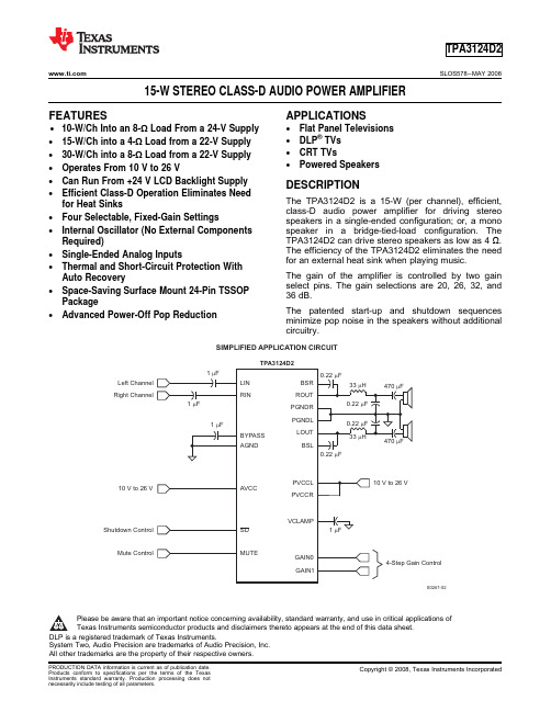
TPA3124D2
........................................................................................................................................................................................................ SLOS578 – MAY 2008
I/O Bootstrap I/O for left channel
P Power supply for left-channel H-bridge, not internally connected to PVCCR or AVCC
O Class-D -H-bridge positive output for left channel
The gain of the amplifier is controlled by two gain select pins. The gain selections are 20, 26, 32, and 36 dB.
The patented start-up and shutdown sequences minimize pop noise in the speakers without additional circuitry.
These devices have limited built-in ESD protection. The leads should be shorted together or the device placed in conductive foam during storage or handling to prevent electrostatic damage to the MOS gates.
TDV-3124 中文说明书

数码摄像机用户手册TDV-31241摄像机部件-------------------------------------------------------------------------------4 2拍照前的准备----------------------------------------------------------------------------6装入电池 (6)插入存储卡 (7)格式化存储卡 (8)设置语言 (8)LCD 显示屏 (9)3 基本操作--------------------------------------------------------------------------------12打开和关闭摄像机 (12)模式转换 (12)拍照 (13)如何自拍和连拍功能 (13)录像 (14)录音 (15)4设置摄像机------------------------------------------------------------------------------15拍照模式菜单 (15)录像模式菜单 (17)设置菜单 (18)5 回放--------------------------------------------------------------------------------------20回放录像 (20)回放照片 (20)回放录音 (20)回放模式下的其它功能 (21)6连接---------------------------------------------------------------------------------------24将摄像机与电视机相连 (24)将图像下载到计算机 (24)使用读卡器 (25)通过USB线将摄像机连接到计算机 (25)7安装软件---------------------------------------------------------------------------------26安装软件 (26)安装摄像头驱动 (27)怎样使用摄像头功能 (27)8技术指标---------------------------------------------------------------------------------29感谢你购买本数码摄像机。
WDR-3124A 工業無線路由器说明书
WDR-3124A系列工業802.11n/HSPA無線路由器特色與優點•通用GSM/GPRS/HSPA蜂巢式網路通訊•2.4-GHz/5-GHz雙頻300Mbps Wi-Fi通訊•內建4埠Gigabit乙太網路交換器•具有雙電源輸入和內建DI/DO支援的工業設計•雙SIM卡的蜂巢式網路連結備援•GuaranLink提供可靠的蜂巢式網路連線•天線和電源隔離設計,防止干擾認證簡介WDR-3124A工業無線路由器結合802.11n和蜂巢式網路技術,可提供彈性的無線網路連線。
WDR-3124A隨附有內建天線和電源隔離,適用於任何嚴苛的工業環境。
WDR-3124A採用DIN軌道安裝、寬操作溫度範圍型號和IP30外殼,是適用於任何工業無線應用而且方便可靠的解決方案。
WLAN和蜂巢式網路連線•高速無線連線,最高可達300Mbps的資料傳輸速率•WLAN AP/用戶端路由器運作模式支援•GSM/GPRS/HSPA連線的通用蜂巢式網路頻段支援有效的隔離和備援設計•電源備援的雙電源輸入•蜂巢式網路連線備援的雙SIM卡支援•防止無線電干擾的天線隔離•電源絕緣保護的電源隔離規格Cellular InterfaceCellular Standards GSM,GPRS,EDGE,UMTS,HSPABand Options UMTS/HSPA800MHz/850MHz/900MHz/1900MHz/2100MHzUniversal quad-band GSM/GPRS/EDGE850MHz/900MHz/1800MHz/1900MHz HSPA Data Rates14.4Mbps DL,5.76Mbps ULEDGE Data Rates237kbps DL,237kbps ULGPRS Data Rates85.6kbps DL,85.6kbps ULNo.of SIMs2SIM Control Voltage3VCellular Antenna Connectors1SMA femaleWLAN InterfaceWLAN Standards802.11a/b/g/n802.11i Wireless SecuritySpread Spectrum DSSS,OFDMModulation Type802.11b:CCK@11/5.5Mbps802.11b:DQPSK@2Mbps802.11b:DBPSK@1Mbps802.11a/g:64QAM@54/48Mbps802.11a/g:16QAM@36/24Mbps802.11a/g:QPSK@18/12Mbps802.11a/g:BPSK@9/6Mbps802.11n:64QAM@300Mbps to BPSK@6.5Mbps Frequency Band for EU(20MHz operating channels) 2.142to2.472GHz(13channels)5.180to5.240GHz(4channels)Frequency Band for US(20MHz operating channels) 2.412to2.462GHz(11channels)5.180to5.240GHz(4channels)5.745to5.825GHz(5channels)Wireless Security WEP encryption(64-bit and128-bit)WPA/WPA2-Enterprise(IEEE802.1X/RADIUS,TKIP,AES)WPA/WPA2-PersonalSSID broadcast enable/disableTransmission Rate802.11a/g:6,9,12,18,24,36,48,54Mbps802.11b:1,2,5.5,11Mbps802.11n HT20:6.5to150Mbps(MCS0to MCS7)802.11n HT40:150to300Mbps(MCS8to MCS15) Transmitter Power for802.11a20±1.5dBm@6to24Mbps19±1.5dBm@36Mbps16±1.5dBm@48Mbps15±1.5dBm@54MbpsTransmitter Power for802.11b23±1.5dBm@1Mbps20±1.5dBm@5Mbps19±1.5dBm@11MbpsTransmitter Power for802.11g20±1.5dBm@6to24Mbps19±1.5dBm@36Mbps18±1.5dBm@48Mbps17±1.5dBm@54MbpsTransmitter Power for802.11n(2.4GHz)20±1.5dBm@MCS0/820MHz20±1.5dBm@MCS0/840MHz16±1.5dBm@MCS7/1520MHz16±1.5dBm@MCS7/1540MHzTransmitter Power for802.11n(5GHz)19±1.5dBm@MCS0/820MHz18±1.5dBm@MCS0/840MHz14±1.5dBm@MCS7/1520MHz14±1.5dBm@MCS7/1540MHzReceiver Sensitivity for802.11a-92dBm@6Mbps-89dBm@9Mbps-85dBm@12Mbps-82dBm@18Mbps-80dBm@24Mbps-76dBm@36Mbps-74dBm@48Mbps-72dBm@54MbpsReceiver Sensitivity for802.11b-90dBm@1Mbps-88dBm@2Mbps-86dBm@5.5Mbps-84dBm@11MbpsReceiver Sensitivity for802.11g-85dBm@6Mbps-84dBm@9Mbps-83dBm@12Mbps-82dBm@18Mbps-80dBm@24Mbps-76dBm@36Mbps-70dBm@48Mbps-70dBm@54MbpsReceiver Sensitivity for802.11n(2.4GHz)-70dBm@MCS720MHz-68dBm@MCS1520MHz-65dBm@MCS740MHz-63dBm@MCS1540MHzReceiver Sensitivity for802.11n(5GHz)-70dBm@MCS720MHz-67dBm@MCS1520MHz-68dBm@MCS740MHz-66dBm@MCS1540MHzWLAN Antenna Connector2RP-SMA femaleGPS InterfaceGPS Antenna Connector1SMA femaleEthernet Interface10/100/1000BaseT(X)Ports(RJ45connector)4Standards IEEE802.3for10BaseTIEEE802.3ab for1000BaseT(X)IEEE802.3u for100BaseT(X)Total Port Count4LED InterfaceLED Indicators PWR1,PWR2,STATUS,FAULT,CELLULAR SIGNAL,WIFI SIGNAL,WLAN,SIM1,SIM2,2G,3G,GPSInput/Output InterfaceAlarm Contact Channels1,Relay output with current carrying capacity of1A@24VDCButtons Reset buttonDigital Input Channels2Digital Inputs+13to+30V for state13to-30V for state0Ethernet Software FeaturesManagement ARP,DDNS,DHCP Client,DNS,HTTP,SMTP,SNMPv1/v2c/v3,TCP/IP,Telnet,UDP,Web Console,Wireless Search Utility,Serial Console,Telnet Console,Remote SMSControl,OnCell Central Manager,GuaranLinkSecurity HTTPS,IPsec,SSHTime Management SNTPRouting NAT,Port forwardingFirewall Filter:MAC,IP protocol,port-basedIPsec VPNAuthentication MD5and SHA(SHA-256)PSK/X.509/RSAConcurrent VPN Tunnels Max.5IPsec VPN tunnelsProtocols IPsecEncryption DES,3DES,AES,MD5,SHA-1,DH2,DH5Physical CharacteristicsHousing AluminumIP Rating IP30Dimensions66.3x124x90mm(2.61x4.88x3.54in)Weight1,280g(2.82lb)Environmental LimitsOperating Temperature Standard Models:0to55°C(32to131°F)Wide Temp.Models:-30to70°C(-22to158°F)Storage Temperature(package included)-40to85°C(-40to185°F)Ambient Relative Humidity5to95%(non-condensing)Power ParametersPower Connector Terminal blockInput Voltage Redundant dual inputs,12to48VDCInput Current0.7A@12VDC,0.2A@48VDCReverse Polarity Protection SupportedStandards and CertificationsSafety EN60950-1,UL60950-1EMC EN61000-6-2/-6-4EMI CISPR32,FCC Part15B Class AEMS IEC61000-4-2ESD:Contact:8kV;Air:15kVIEC61000-4-3RS:80MHz to1GHz:10V/mIEC61000-4-4EFT:Power:2kV;Signal:2kVIEC61000-4-5Surge:Power:2kV;Signal:1kVIEC61000-4-6CS:10VIEC61000-4-8PFMFRadio Frequency EN301489-1,EN301489-7,EN301511,EN301908,EN300328,EN301893,FCC IDSLE-WAPN005MTBFTime382,851hrsStandards Telcordia SR332WarrantyWarranty Period5yearsDetails See /tw/warrantyPackage ContentsDevice1x WDR-3124A Series wireless router1Installation Kit1x DIN-rail kit1.已啟動的SIM卡(未隨附)必須由第三方蜂巢式網路服務供應商提供。
- 1、下载文档前请自行甄别文档内容的完整性,平台不提供额外的编辑、内容补充、找答案等附加服务。
- 2、"仅部分预览"的文档,不可在线预览部分如存在完整性等问题,可反馈申请退款(可完整预览的文档不适用该条件!)。
- 3、如文档侵犯您的权益,请联系客服反馈,我们会尽快为您处理(人工客服工作时间:9:00-18:30)。
上海鼓风机厂有限公司新疆其亚一次风机项目说明书安装维护说明书产品型号:1854B/1245工程号:3124一次风机编制:文香妮校对:徐健审核:王冲强上海鼓风机厂有限公司二○一四年四月目录1 风机说明2 风机的存储说明3 风机的安装4 风机调试与运行5 风机的检修与维护6 风机的故障分析与排除附录:1.风机的总装图2.风机的性能参数表1.风机说明1.1 风机概述1.1.1本风机是我公司按德国TLT公司引进技术设计制造的离心风机。
与国内同类风机相比,具有设计效率高,调节范围广等特点。
1.1.2本说明书为新疆农三师一次风机项目所配套的产品说明书,规定了此风机在安装、调试运转、维护、保养等方面的操作说明和技术要求。
现场实际操作时,如与本说明书所述结构形式有不符之处,可在现场作相应的处理,使风机处于最佳安装及运行状态。
1.1.3对电动机、油站、液力偶合器、联轴器等配套件的安装只作接口处的安装要求,详细的安装维护等要求按各配套件的说明书和外形图等技术资料规定。
1.1.4本说明书不包括电控、自控、外购配套件等风机以外的安装、使用、维护要求。
1.1.5在安装施工时,除按说明书外,还应按风机随机文件、图纸等技术资料和电机、油站、偶合器(如有配套)等配套件的技术文件图纸技术资料规定进行。
1.2 一般规定1.2.1本说明书与专用说明书、产品图纸、技术资料是指导安装的一个整体,所以风机在安装前必须将说明书、图纸等技术资料同时熟悉和理解。
1.2.2风机在安装前应熟悉风机的结构形式和技术要求,检查基础的正确和可靠情况。
1.2.3风机的进排气管道在安装时,不得将其重量作用在风机主体上。
连接后应复测机组水平和主要间隙应符合要求。
1.2.4风机的剖分面,进排气口法兰等连接处均安置软质垫物以防止漏气。
管路与风机连接时,法兰面应对中心并平行。
1.2.5风机安装前应清理基础上的垃圾杂物,并备有调节高低的平、斜垫铁。
1.2.6在粗安装放上底脚螺栓,旋上螺母后,在面上还应留有足够的螺栓长度,以便调整中心高时使用。
1.2.7安装过程必须注意安全,对设备核对清楚重量后进行起吊。
1.3 风机的命名规则1.3.1:风机型号:1854B/1245表示意义为:185 = ( 叶轮叶片出口直径/叶轮进口直径 ) × 1004 ------------------机翼模型系列B -------------------叶轮为单吸双支撑1245--------------------叶轮进口直径(mm)1.3.2: 风机的旋向:进口120°,出口0°(从电机端视)A:从电动机端视,叶轮旋转方向为顺时针时,规定此风机为顺转风机,也称为右转风机。
B:从电动机视,叶轮旋转方向为逆时针时,规定此风机为逆转风机,也称为左转风机。
进口旋向:风机的进口位置(进口方向)按叶轮旋转方向根据安装角的不同规定的位置见下图1.4 数据表及性能曲线本风机是按用户提供的技术参数设计,技术参数如下表(风机的性能曲线参见附录2。
用户可通过改变调节门的叶片开度来达到运行所需要的工况点。
工况点TB风量(m3/s) 90.52风机总压升(Pa) 13514进口全压(Pa) -400进口处介质温度(℃) 30出口处介质温度(℃) 43.64进口处介质密度(kg/m3) 1.070风机效率(%)88%风机轴功率(kW) 1336.9风机转速(r/min) 1480电动机功率(kW) 1500电动机转速(r/min) 14801.5风机结构介绍风机主要由机壳部、进风口部、传动部、叶轮部、轴承箱部、调节门部等部件组成。
风机经联轴器联接,由电动机驱动。
电动机型号为YBKK560-4 本风机的结构如下图所示:风机的主要部件清单:序号名称图号1 叶轮3124.26.01-12 主轴3124.25.01.013 轴承箱及轴承GXTA130.01-1 GXTA160.02-14 机壳部3124.01.01-1 6 调节门K1500.30.01-17进/出口膨胀节3124.77.10-1 3124.77.40-18 进气箱3124.04.01-1风机主要部件详细介绍如下:1.5.1 叶轮叶轮是风机的心脏部件,是由轮盖、叶片、中盘(后盘)采用优质的低合金钢板焊接而成.此风机的叶轮型式为单吸入式,叶片流道型式为机翼型叶片,此种型线流动损失小,效率高的特点,总共有8片叶片。
轮盖的进口端为圆弧形。
叶片与轮盖、轮盘的连接均采用焊接方式,材料均为15MnV。
叶轮与主轴的连接采用法兰结构,而不是轮毂连接(见下图),从而较大地减轻了叶轮的重量。
同时,防止了叶轮在高速旋转过程中,离心力造成了叶轮与主轴的配合松动。
叶轮与主轴共用12只高强度螺栓紧固,所有螺栓均用止动垫圈锁紧,同时主轴法兰轴肩部又能阻止螺栓本身的转动,故这种连接方式是非常安全可靠的,同时又能承受较大的扭矩。
叶轮与主轴装配后做动平衡试验,以保证转子部的平稳运转。
平衡精度为2.5级,允许质心偏移量为16.1μm。
故在安装和检验时,不得将叶轮与主轴拆开。
1.5.2 主轴主轴为整体锻造轴,两端用滚动轴承支承,一端经联轴器与电机相连。
主轴材质为45-5,主轴具有足够的刚度和强度。
1.5.3 轴承箱及轴承轴承箱为铸铁结构,为方便安装和检修,分上、下剖分两部分。
在轴承箱上有油位指示器和测量轴承温度元件。
靠近联轴器端的轴承箱两侧均设有油封,防止轴承箱内飞溅的油向外泄漏,另一端轴承箱靠近风机侧有油封,外端有端盖。
风机的轴承型号分别为22226E.C3,22232E.C3滚子轴承,采用的SKF/FAG的产品。
风机每个轴承均配置WZPT2-31热电阻各两支和WSS-481双金属温度计一只,用于测量轴承温度。
风机每个轴承均配置测振探头,用于测量轴承箱的振动。
轴承采用的是润滑油润滑,在轴承箱上开有水冷却结构,冷却管为G1”,进水量为1.2 m3/h,水压为0.2-0.3Mpa.润滑油用的是N46机械油,也可选用N68机械油。
润滑油的过滤精度要求直径超过25um的颗粒应阻挡95%,对所有直径超过30um的颗粒应能阻挡99.5%。
1.5.4 联轴器部联轴器采用膜片联轴器。
型号为JM1J14(C=210),宁波伟隆产品。
1.5.5 壳体风机壳体由机壳及进气箱组成,均为材质Q235A的钢板焊接而成。
为了加强机壳和进气箱的刚度,在它们的侧板上均焊有加强扁钢,在机壳和进气箱的内部焊接钢管,从而确保机壳和进气箱在运输、安装和运行过程中不发生较大的变形。
机壳一般剖分上、下剖分结构,在剖分平面等用软质垫物进行密封。
机壳和进气箱均设有人孔门,便于维护和检修。
机壳和进气箱的底部一般设有排污孔,并配上闸阀或球阀,便于排放壳体内部的杂物。
机壳轴向两端设有密封,防止气体的泄漏。
注意:此风机考虑到运输限制,在我公司已剖分成若干部分,方便运输,到用户现场后,再组装焊接为一体。
1.5.6 进风口进风口也称集流器,制成收敛的流线型管道,从而将气流均匀地以一定流速导入叶轮,改善了叶轮的内部流动。
进风口插入叶轮的长度b及与叶轮进口圈的间隙a直接关系到风机的性能.间隙过大,由于机壳与进风口之间有压力差,机壳内的气流就通过间隙返回叶轮进口,形成泄露损失,间隙越大,损失越大。
故进风口在装配和检修时,要严加注意,尽量保证图纸的要求。
1.5.7 挡板调节门挡板调节门的开闭是由电动执行器通过连杆来带动的。
通过调节挡板调节门挡板的开启度,可以改变风机的运行工况点,以满足用户不同的运行要求。
从电机侧看,调节门的开启方向和气流的方向相一致。
1.5.8进、出口膨胀节在风机的进、出口装有进口膨胀节,它是一个补偿风机进口与连接管道之间安装误差的挠性接头。
膨胀节由复合材料、金属导向板和紧固法兰组成。
1.5.9密封在主轴伸出机壳与进气箱处设有密封板密封,以减少机壳与进气箱的漏气损失。
此处的密封部由两块压板、一块补板、一块密封板、一块铜皮用螺钉连接而成(参见图)。
而中分面法兰等其它法兰连接处的密封是靠密封绳完成的。
2.风机的存储2.1风机的存储2.1.1短期存放(少于30天)1.存放在干净,干燥的地点;2.覆盖机加工零件和机械组件以防止水汽和灰尘;3.通电并定期检查电机加热器;4.遵循“存放期间的维护”所述的建议2.1.2长期存放(多于30天)与短期存放相同,加上下列说明1.用规定的润滑剂将轴承充注到量以防污染;2.用润滑脂涂复机加工表面;3.将保护盖加到工厂组装的风机的入口和出口上;4.遵循“存放期间的维护”所述的建议2.1.3存放期间的维护(长期和短期)1.对于工厂组装的风机,每星期转动轴,防止轴承中永久性的“凝固”;2.如有可能,每两个星期运行风机15分钟,确保清洁导管,使轴承和整个系统保持在工作状态;3.每星期转动电机、盘车机构和液力偶合器;4.维持所有轴承中的正确油位;5. 仅以水平位置存放风机转子和电机;2.1.4风机部件在现场的存储要求,需按照下表进行序号部件名称存储要求1 机壳上半部室内,允许室外;覆盖防雨布,防雨布下放干燥剂;法兰面和螺栓孔涂油脂;机壳与托架一起存放2 机壳下半部室内,允许室外;覆盖防雨布,防雨布下放干燥剂;法兰面和螺栓孔涂油脂;机壳与托架一起存放3 风机转子室内,允许室外;覆盖防雨布,防雨布下放干燥剂;主轴表面涂防锈优质,外部包覆塑料纸;相对湿度不得大于70%;温度不得大于40℃4 进风口部室内,允许室外;覆盖防雨布,防雨布下放干燥剂;;相对湿度不得大于70%;温度不得大于40℃5 调节门室内,允许室外;覆盖防雨布,防雨布下放干燥剂;;相对湿度不得大于70%;温度不得大于40℃6 轴承箱室内,允许室外;覆盖防雨布,防雨布下放干燥剂;;相对湿度不得大于70%;温度不得大于40℃7 进/排气膨胀节室内,允许室外;覆盖防雨布,防雨布下放干燥剂;法兰面和螺栓孔涂油脂;与托架一起存放8 风机附件仅限室内存放;螺纹要适时涂防锈油脂;相对湿度不得大于70%;温度不得大于40℃;注意通风;木箱内放干燥剂9 电动执行器仅限室内存放;螺纹要适时涂防锈油脂;相对湿度不得大于70%;温度不得大于40℃;注意通风;木箱内放干燥剂10 电机油站仅限室内存放;禁止开箱;相对湿度不得大于70%;温度不得大于40℃;12 电机仅限室内存放;禁止开箱;相对湿度不得大于70%;温度不得大于40℃;3.风机的安装风机的安装必须严格按下列步骤进行:⑴安装前的准备工作1)按照装箱清单开箱清点风机的零件、部件、配套件、随机备件、技术资料等齐全,完整,核对转子的旋转方向,机壳进排气的方向和安装位置,与设计是否相符。
2)清洗:风机在安装前,应对零件清洗,如转子、主轴的轴承档、滚动轴承、轴承箱内部联轴器等精加工件。