共立3125中文使用说明书
共立3125绝缘电阻仪使用说明注意事项
共立3125绝缘电阻仪使用说明注意事项一、注意事项:1.仪器使用前请查看仪器是否完好,是否有损坏或松动的零件,以及是否有明显的污垢,如果发现有问题,应立即停止使用。
2.仪器应放置在干燥、无腐蚀性气体和有一定通风的地方,避免阳光直射或有潮湿的地方。
3.使用前请确保绝缘电阻仪与被测试设备处于零电位状态,以防止可能出现的电击伤害。
4.在使用绝缘电阻仪前,请先熟悉仪器的结构和功能,并按照正确的操作步骤进行操作,避免操作错误导致的故障和危险。
5.进行测量时,请确保被测试设备的电源已断开,并检查附近是否有可能产生电磁干扰的设备,并将其关闭或远离。
6.每次使用后,请及时清洁仪器,用干燥的软布擦拭仪器表面,切勿用水或化学溶剂清洗。
7.仪器长时间不使用时,请按照说明书的要求进行存储,以防止仪器老化或损坏。
二、使用说明:1.打开仪器,在仪器面板上选择所需的电阻测量范围和电压(通常为500V或1000V)。
2.连接仪器的测试线,将一个测试线连接到仪器的"HI"插口,另一个测试线连接到仪器的"LO"插口。
3.将"HI"测试线连接到被测试设备的绝缘部分,将"LO"测试线连接到被测试设备的接地部分,确保连接稳固。
4.按下仪器面板上的"TEST"按钮,仪器将进行电阻测量,在测量过程中仪器会显示电阻值。
5.测量完成后,仪器将自动断开电源,并显示最终的测量结果。
请及时记录测量结果。
6.使用完毕后,请关闭电源,将仪器放置在干燥通风的地方。
三、维护保养:1.定期检查仪器的电源线是否损坏,如有损坏请及时更换。
3.定期清洁仪器的表面和连接线,确保仪器在正常使用条件下工作。
4.仪器长时间不使用时,应存放在干燥通风的地方,同时避免阳光直射。
总之,正确使用和保养共立3125绝缘电阻仪能有效延长其使用寿命,并确保测量结果的准确性。
如果发现任何故障或异常情况,请立即停止使用,并通过合适的渠道进行维修或更换。
THS3125CPWPRG4中文资料
Copyright 2001, Texas Instruments Incorporated
1
元器件交易网
THS3122 THS3125
SLOS382 − SEPTEMBER 2001
AVAILABLE OPTIONS PACKAGED DEVICE TA 0°C to 70°C −40°C to 85°C SOIC-8 (D) THS3122CD THS3122ID SOIC-8 PowerPAD (DDA) THS3122CDDA THS3122IDDA SOIC-14 (D) THS3125CD THS3125ID TSSOP-14 (PWP) THS3125CPWP THS3125IPWP EVALUATION MODULES THS3122EVM THS3125EVM
† Stresses beyond those listed under “absolute maximum ratings” may cause permanent damage to the device. These are stress ratings only, and functional operation of the device at these or any other conditions beyond those indicated under “recommended operating conditions” is not implied. Exposure to absolute-maximum-rated conditions for extended periods may affect device reliability. NOTE 1: The THS3122 and THS3125 may incorporate a PowerPAD on the underside of the chip. This acts as a heatsink and must be connected to a thermally dissipating plane for proper power dissipation. Failure to do so may result in exceeding the maximum junction temperature which could permanently damage the device. See TI Technical Brief SLMA002 for more information about utilizing the PowerPAD thermally enhanced package. DISSIPATION RATING TABLE PACKAGE D-8 DDA D-14 PWP θJA 95°C/W‡ 67°C/W 66.6°C/W‡ 37.5°C/W TA = 25°C POWER RATING 1.32 W 1.87 W 1.88 W
Canon imageRUNNER C3125i A3 彩色多功能打印机说明书
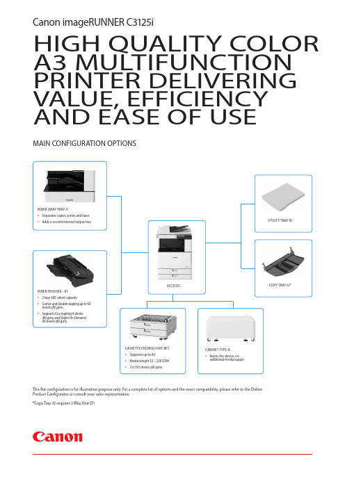
HIGH QUALITY COLOR A3 MULTIFUNCTION PRINTER DELIVERING VALUE, EFFICIENCY AND EASE OF USECanon imageRUNNER C3125iThis flat configuration is for illustration purpose only. For a complete list of options and the exact compatibility, please refer to the Online Product Configurator or consult your sales representative.*Copy Tray-J2 requires 3 Way Unit-D1MAIN CONFIGURATION OPTIONSiR C3125iCABINET TYPE-R•Raises the device, no additional media supplyCASSETTE FEEDING UNIT-AP1• Supports up to A3• Media weight 52 – 220 GSM •2 x 550 sheets (80 gsm)UTILITY TRAY-B1COPY TRAY-J2*INNER 2WAY TRAY-J1• Separates copies, prints and faxes •Adds a second internal output trayINNER FINISHER – K1• 2-tray, 600 -sheet capacity • Corner and double stapling up to 50 sheets (80 gsm)•Supports Eco stapling 4 sheets (80 gsm) and Staple On Demand 40 sheets (80 gsm)MAIN UNITMachine type A3 Color Laser MultifunctionalCore functions Print, Copy, Scan, Send and Optional Fax Processor Canon Dual Custom Processor (Shared) Control Panel12.7 cm (5 inch) TFT LCD WVGA Color Touch panel Memory Standard: 2.0GB RAMInterface Connection NETWORKStandard: 1000BaseT/100Base-TX/10Base-T,Wireless LAN (IEEE802.11b/g/n)Optional: NFCOTHERSStandard: USB 2.0 (Host) x 2, USB 2.0 (Device) x 1Optional: Copy Control InterfacePaper Supply capacity (A4, 80gsm)Standard: 1,200 Sheets100-sheets Multi-purpose tray x 1, 550-sheets Paper cassette x 2Maximum: 2,300 Sheets(with optional Cassette Feeding Unit-AP1)Paper output capacity (A4, 80gsm)Standard: 250 Sheets Maximum: 700 Sheets(with Inner Finisher-K1 and Copy Tray-J2)Finishing capabilities Standard model: Collate, GroupFinisher model (Inner Finisher-K1): Collate, Group,Offset, Staple, Eco Staple, Staple On Demand Supported Media Types Multi-purpose Tray:Thin, Plain, Heavy*, Recycled, Coated*, Color,Tracing, Bond, Transparency, Label, Pre-punched,Envelope* SRA3 is unsupported for Coated (257-300gsm) andHeavy (257-300gsm) paper.Paper Cassette (Upper/Lower Cassette):Thin, Plain, Heavy, Recycled, Color, Bond,Transparency, Pre-punched, Envelope**Lower Cassette: Envelope Feeder Attachment A is required. Supported media sizes Multi-purpose tray:Standard size: SRA3, A3, A4, A4R, A5, A5R, A6R,B4, B5, B5R, Envelope [COM10 No.10, Monarch,ISO-C5, DL]Custom size: 98.4 x 139.7 mm to 320.0 x 457.2 mmPaper Cassette (Upper Cassette):Standard size: A4, A5, A5R, A6R, B5Custom size: 105.0 x 148.0 mm up to 297.0 x215.9 mmEnvelope: ISO-C5Paper Cassette (Lower Cassette):Standard size: A3, A4, A4R, A5, A5R, A6R, B4,B5, B5RCustom size: 105.0 x 148.0 mm up to 304.8 x 457.2 mmEnvelope: [COM10 No.10, Monarch, DL]**Envelope Feeder Attachment A is required. Supported media weights Multi-purpose tray: 52 to 300 gsm** SRA3 is unsupported for Coated (257-300gsm) andHeavy (257-300gsm) paper.Paper Cassette (Upper/Lower Cassette):52 to 220 gsmDuplex: 52 to 220 gsmWarm-Up Time From Sleep Mode: 10 Seconds or LessFrom Power On: 19 Seconds or Less**Time from device power-on, until copy ready(not print reservation)Dimensions (W x D x H)565 x 664 x 880 mmInstallation Space (W x D)1241 x 1217 mm*with Cassette open + 100 mm gap around the main body Weight Approx. 67.3 kg without tonerPRINT SPECIFICATIONSPrint Speed (BW/CL)Up to 25/25 ppm (A4, A5, A5R, A6R), Up to 15/15ppm (A3), Up to 20/20 ppm (A4R)Print Resolution (dpi)600 x 600, 1,200 x 1,200Page descriptionlanguagesStandard: UFR II, PCL6, Adobe®PostScript®3TM Direct Print Supported file types: PDF, EPS, TIFF/JPEG, XPS**XPS is supported from LPR command print only.Printing from mobile andcloudAirPrint, Mopria, Google Cloud Print, CanonBusiness Print and uniFLOW OnlineA range of software solutions is available toprovide printing from mobile devices andcloud-based services depending on yourrequirements. Please contact your salesrepresentative for further information.Fonts PCL fonts: 93 Roman, 10 Bitmap fonts, 2 OCRfonts, Barcode fonts*, PS fonts: 136 Roman* Barcode Printing Kit-D1 is requiredPrint Features Secure Print, Header/Footer, Page Layout,Two-sided Printing, Mixed Paper Sizes/Orientations, Toner Reduction, Poster Printing,Print DateOperating System UFRII: Windows®7/8.1/10/Server2008/Server2008R2/Server2012/Server2012 R2/Server2016/Server2019, Mac OS X (10.10 or later)PCL: Windows®7/8.1/10/Server2008/Server2008R2/Server2012/Server2012 R2/Server2016/Server2019PS: Windows®7/8.1/10/Server2008/Server2008R2/Server2012/Server2012 R2/Server2016/Server2019, Mac OS X (10.10 or later)PPD: Windows®7/8.1/10, MAC OS X (10.9 or later)COPY SPECIFICATIONSCopy Speed (BW/CL)Up to 25/25 ppm (A4, A5, A5R, A6R), Up to 15/15ppm (A3), Up to 20/20 ppm (A4R)First-Copy-Out Time (A4)(BW/CL)Approx. 5.9/8.2 seconds or lessCopy resolution (dpi)600 × 600Multiple Copies Up to 999 copiesCopy Density Automatic or Manual (9 Levels) Magnification Variable zoom: 25% - 400% (1% Increments)Preset reduction/enlargement: 25%, 50%, 70%,100% (1:1) / 141%, 200%, 400%Copy Features Preset R/E Ratios by Area, Two-Sided, DensityAdjustment, Original Type Selection, Book to TwoPages, Two-sided Original, Sort, N on 1, Different SizeOriginals, Sharpness, Erase Frame, Copy IDCard, Copy Passport, Color ModeSCAN SPECIFICATIONSType Standard: Duplexing Automatic Document Feeder[2-sided to 2-sided (Automatic with DADF)]Optional: Color Platen (Platen Cover-Y2) Document Feeder PaperCapacity (80 gsm)100 SheetsAcceptable Originals andweightsPlaten: Sheet, Book, and 3-Dimensional objectsDocument Feeder media weight:1-sided scanning: 38 to 128 gsm (BW),64 to 128 gsm (CL)2-sided scanning: 50 to 128 gsm (BW),64 to 128 gsm (CL)Supported media sizes Platen: max. scanning size: 297.0 x 431.8 mmDocument Feeder media size:A3, A4, A4R, A5, A5R, B4, B5, B5R, B6Custom size: 128.0 x 139.7 mm to 297.0 x 431.8 mm Scan Speed(ipm: BW/CL; A4)1-sided Scanning:55/55 (300 x 300 dpi, send),30/30 (600 x 600 dpi, copy),2-sided Scanning:27.5/27.5 (300 x 300 dpi, send),15/15 (600 x 600 dpi, copy)Scan Resolution (dpi)Scan for Copy: up to 600 x 600Scan for Send: (Push) up to 600 x 600,(Pull) up to 600 x 600Scan for Fax: up to 600 x 600Pull Scan Specifications ScanGear MF. For both TWAIN and WIASupported OS: Windows® 7/8.1/10Scan Method Push Scan, Pull Scan, Scan to Network, Scan tomemory media (USB Memory Key), Scan tocloud-based services (uniFLOW)SEND SPECIFICATIONSDestination Standard: E-mail/Internet FAX (SMTP), SMB, FTPOptional: Super G3 FAXAddress Book LDAP (50)/Local (300)/Speed dial (281)Send resolution (dpi)Push: 300 x 300 (Email/SMB/FTP), 192 x 204 (IFAX)Pull: 50 x 50, 75 x 75, 150 x 150, 200 x 200, 300 x300, 400 x 400, 600 x 600 Communication protocol FTP (TCP/IP), SMB (TCP/IP), SMTPFile Format Standard: TIFF, JPEG*, PDF(Compact, Searchable, Encrypted, Digital Signature)*Single Page OnlyUniversal Send Features Original Type Selection, Two-sided Original,Different-size Originals, Density Adjustment,Sharpness, File Name, Subject/Message, Reply-to,E-mail Priority, TX Report, Original ContentOrientationFAX SPECIFICATIONSMaximum Number ofConnection Lines1Modem Speed Super G3: 33.6 kbpsG3: 14.4 kbpsCompression Method MH, MR, MMR, JBIGResolution (dpi)400 x 400 (Ultra Fine), 200 x 400 (SuperFine), 200 x 200 (Fine/Photo), 200 x 100(Normal)Sending/Receiving Size Sending: A3, A4, A4R, A5*2, A5R*2, B4, B5*1, B5R*2 Receiving: A3, A4, A4R, A5R, B4, B5, B5R*1 Sent as B4*2 Sent as A4FAX memory Up to 512 pagesSpeed dials Max. 281Group dials/destinations Max. 299 dialsSequential broadcast Max. 310 addressesMemory backup YesFax Features Direct Send, TX Report, SequentialBroadcastingSECURITYSPECIFICATIONSAuthentication and Access Control Standard:Department ID Authentication (Department ID and PIN Login, Function Level Login), uniFLOW Online Express (PIN Login, Card Login, Card and PIN Login)Document Security Print Security (Secure Print, uniFLOW SecurePrint*), Scan Security (Encrypted PDF, DeviceSignature PDF), Send Data Security(Restricted E-mail/File send functions,Confirming FAX number, Allow/Restrict FaxDriver Transmissions, Allow/Restrict Sendingfrom History)*Requires uniFLOW Online / uniFLOW Network Security IPSec, IEEE802.1X authentication, SNMPv3,Firewall Functionality (IP/MAC AddressFiltering), Enabling/Disabling Remote UI, G3FAX separation from LAN, USB Port separationfrom LANDevice Security Standard: Storage Initialize, Job LogConceal Function, Protecting MFDSoftware IntegrityDevice Management and Auditing Standard: Administrator Password, DigitalCertificate and Key Management, SecurityPolicy SettingENVIRONMENTALSPECIFICATIONSOperatingEnvironmentTemperature: 10 to 30 ºCHumidity: 20 to 80% RH (Relative Humidity)Power source110-127V 60Hz 15A220-240V 50/60Hz 10APower consumption Maximum: Approx. 1,5 kW or LessAverage: Approx. 412.0W (120V); 431.0 W (230V)(while printing/copying)Standby: Approx. 35.1 (120V) 34.3 W (230V)*1Sleep mode: Approx. 2W*2, Approx. 1W*3*1 Reference value: measured one unit*2 Wireless LAN power serve mode OFF*3 Wireless LAN power serve mode ON*2,*3S leep mode is not available in all circumstances due tocertain settings.Typical Electricity Consumption (TEC): 0.29 kWh** As per US ENERGY STAR Version 3.0Noise levels (BW/CL)Sound Power Level (LWA,m)(1-sided/2-sided)Active (BW): 6.1/6.4 B*1, Kv 0.3/0.3 B*1Active (CL): 6.2/6.4 B*1, Kv 0.3/0.3 B*1Sound Pressure (LpAm)Bystander's position: (1-sided/2-sided)Active (BW): 47/50 dB*1,Active (CL): 48/50 dB*1,Standby: No noise*2*1R eference value: measured only one unit withISO7779, described with ISO9296:2017*2N o noise means that the emission sound pressurelevel of each bystander position is lower than theabsolute standard with the background noise ofISO 7779.Standards Blue AngelCONSUMABLESToner Cartridge/s GPR-53 TONER BK/C/M/YToner (EstimatedYield @ 5% Coverage)GPR-53 TONER BK: 36,000 pagesGPR-53 TONER C/M/Y: 19,000 pagesGPR-53L TONER C/M/Y: 8,500 pagesSOFTWARE ANDPRINTERMANAGEMENTTracking andreportingUniversal Login Manager (ULM):Manage your costs easily by using the embeddedreporting capability to identify and control costson a user-based level by device.uniFLOW Online Express*: Combining with ULMyou can gain further control and highlightexpenditures per users/department and pinpointwhere costs can be scaled down from a centralcloud based location.*Installation, activation and registration requiredRemote managementtoolsiW Management Console:Server-based software for centralisedmanagement of afleet of devices (includes monitoring orconsumables,status monitoring and alerts, distribution of address books,configuration settings, firmware and MEAP applications,meter capture and reporting, driver and resourcemanagement)imageWARE REMOTE:Compatible with imageWARE services viaembedded RDS (Enables meter capture, automaticconsumables management, remote diagnostics andreporting for service providers to offer efficient, fast andproactive maintenance)Content Delivery System:Allows the Remote distribution of firmware, iRoptions and MEAP applications; Remote UserInterface (RUI) Web based interface to eachdevice that helps to provideremote device management and controlCustomization options Application LibraryScanning software ScanGear MF Scanner DriverOptimization tools Canon Driver Configuration ToolPAPER SUPPLY OPTIONSCassette Feeding Unit-AP1Paper Capacity: 550 sheets x 2 (80 gsm) Paper Type: Thin, Plain, Recycled, Color, Heavy, Bond, Transparency, Pre-punchedPaper Size: A3, A4, A4R, A5, A5R, A6R, B4, B5 ,B5R, Custom Size: 105.0 x 148 mm to 304.8 x 457.2 mm Paper Weight: 52 to 220 gsmPower Supply: From the Main Unit Dimensions (W x D x H): 565 x 615 x 248 mm Weight: Approx. 16 kgOUTPUT OPTIONSInner Finisher-K1Tray Capacity (with 80gsm paper):Number of Trays: 2Lower Tray1: A4, A5, A5R, B5: up to 500 sheetsSRA3, A3, A4R, B4, B5R: up to 250 sheetsA6R: up to 30 sheetsUpper Tray2: A4, A5, A5R, B5: up to 100 sheetsSRA3, A3, A4R, A6R, B4, B5R: up to 50 sheetsPaper Weight:Lower Tray1: 52 to 256 gsmUpper Tray2: 52 to 300 gsmStaple Position: Corner, DoubleStaple Capacity:A4/B5: 50 sheets (52 to 90 gsm)A3/B4/A4R: 30 sheets (52 to 90 gsm)Eco Staple:A3/A4/B4/B5: 5 sheets (52 to 64 gsm)4 sheets (65 to 81.4 gsm)3 sheets (82 to 105 gsm)Staple On Demand: approx 40 sheets (80 gsm)Power Supply: From the main unitDimensions (W x D x H): 634 mm × 525 mm × 188 mm(when the extension tray and rotary tray are extended)Weight: Approx. 8 kgSoftware & SolutionsCompatibilityInner 2way Tray-J1Paper Capacity (with 80 gsm paper)-Upper tray:SRA3, A3, A4, A4R, A5, A5R, A6R, B4, B5, B5R,Custom size (98.4 x 139.7 mm to 320.0 x 457.2mm): 100 sheets-Lower tray:A4, A5, A5R, A6R, B5, B5R: up to 250 sheetsSRA3, A3, A4R, B4, Custom Size (98.4×139.7 to320.0×457.2 mm ): up to 100 sheetsPaper Weight: 52 to 300 gsmDimensions (W x D x H): 426 x 407 x 76 mmWeight: 0.7 kg*Requires 3 Way Unit-D1Copy Tray-J2Capacity: 100 sheets (80 gsm)* A4, B5, B5R, A5RDimensions (W x D x H): 444 × 373 × 176 mm(attached to the main unit,when the extensiontray is extended)Weight: Approx. 0.5 kg*Requires 3 Way Unit-D1HARDWAREACCESSORIEScard readers IC Card Reader Attachment-B2COPY CARD READER-F1COPY CARD READER ATTACHMENT-H3others UTILITY TRAY-B13 Way Unit-D1SYSTEM ANDCONTROLLEROPTIONSprint accessories PS Printer Kit-BK1barcode printing BARCODE PRINTING KIT-D1system accessories COPY CONTROL INTERFACE KIT-D1NFC KIT-D1fax accessories SUPER G3 FAX BOARD-AV3OTHER OPTIONSaccessibilityaccessoriesADF ACCESS HANDLE-A1staple cartridge STAPLE-P1Canon U.S.A., Latin America GroupOne Canon ParkMelville, NY 11747/Color_imageRUNNER。
胜利VC3125说明书中文
厂商声明本公司向最初该仪器的购买者承诺:自购买之日起一年内在正常使用的情况下出现质量问题给予免费保修(保险丝、测试线除外)。
本公司不承担在非正常的条件下或不规范使用本表造成的仪器和人员损伤的责任。
要获得本公司的服务,请您与本公司最近的服务中心联系(或将产品连同有关产生问题的说明、邮资一起寄到最近的服务中心)。
本公司不承担在邮递过程中的损坏。
在保修期内且正常使用的情况下,出现质量问题,本公司将免费维修、更换或退款。
然而,如果本公司检测出损坏是由于误操作、更换、事故或不正常的条件下使用或操作而引起的,本公司将收取适当的维修费用,并将修好的产品返还给您。
运回产品维修或校准仪器需经过统一包装”快递”到本公司。
最好将仪器装入出厂纸板箱里以便运输。
如果没有可用的纸板箱,请使用合适且牢固的替代品进行包装,但要保证替代品的减震效果!防止因为运输过程中的震动而使仪器损坏。
对最初购买者有关在运输中的损坏声明仪器运送到购买者处,购买者应立即全面检查仪器,盒子里的所有材料应该对照附带的包装条目进行核对检查,如果仪器以任何方式损坏,应及时通知运送者。
如要修理由于运输而损坏的仪器,请与本公司最近的服务中心联系。
由于运输损坏与运输员的赔偿协商应由顾客来完成。
目录项目页一、安全警告 (5)二、本手册适用型号 (8)三、特点 (8)四、技术规格 (10)五、仪器布局 (16)仪器正面视图 (16)仪器侧面视图 (18)LCD显示 (18)六、测试前的准备 (21)开机 (21)自动关机功能 (21)背光功能 (21)自动关闭背光 (21)检查电池电压 (21)连接测试导线 (22)七、测量 (23)电压测量 (23)绝缘电阻测量 (24)连续测量 (26)定时器测量功能 (26)极化指数测量 (27)吸收比测量 (28)步进电压测量 (29)泄露电流测量 (30)测量端口的电压特性 (31)保护线的使用 (31)温度显示 (32)时间显示 (32)八、使用存储器及通信功能 (33)存储数据 (33)手动存储模式(SAVE) (33)作业存储模式(LOG) (34)阅读存储器数据 (34)清除存储器数据 (35)使用通信功能 (35)九、更该仪器设置 (37)选择设置选项 (37)十、电池更换 (39)十一、专用电源适配器使用方法 (41)十二、保养与维护 (42)十三、注意事项 (43)一. 安全警告本仪器的设计、制造和检测均达到IEC61010-1:2001、IEC61557-1:1997、EC61557-2:1997安全标准要求,本手册包括确保仪器的安全使用及保证仪器的安全状态,使用者所必须遵守的警告和安全条例。
3125说明书
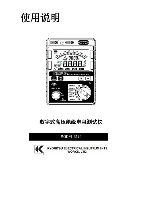
使用说明数字式高压绝缘电阻测试仪目录1.安全警告2.特点3.技术规格4.仪器布局4-1 仪器布局4-2 液晶屏显示5. 测试前的准备5-1 检查电池电压5-2 连接测试导线6. 测试6-1 电压测量6-2 绝缘电阻的测量6-3 连续测量6-4 定时器测量功能6-5 极化指数测量6-6 测量端口的电压特性6-7 保护接线的使用6-8 背光功能6-9 自动关机功能7.电池更换8、附件8-1 测试探棒的金属部分和更换8-2 记录仪适配器8-3 鳄口夹测试线1.安全警告本仪器的设计、制造和检测均达到IEC61010安全标准(电子类测量产品安全要求),本说明书包括确保仪器的安全使用及保证仪器的安全状态,使用者所必须遵守的警告和安全条例。
使用前请先阅读以下说明。
警告 ● 使用前,通读并理解说明书中的操作指南。
● 请将说明书随身保存以确保可随时参阅。
● 必须按指示使用仪器。
● 理解并遵守安全操作指示。
必须严格遵守上述操作说明。
如不遵守,测量时可能会导致人身伤害和仪器毁坏。
本仪器上的标志意思是指为了安全操作本仪器,请使用者参照使用手册的相关部分操作。
以上的电路中测量。
若仪器出现异常请停止使用。
例如:仪器破损或裸露出金属部分。
符号测量前,确认量程开关切换至适当的位置。
2. 特点MODEL3125是由电子控制的4个量程测量绝缘电阻的高压绝缘电阻计。
● 设计达到以下安全标准:IEC 61010-1(CAT.III 600V 污染度2)IEC 61010-031(手持式探针要求标准)● 自动放电功能:测试电容性负荷的绝缘电阻时,测量后自动释放充电电荷。
放电状态可在电压模式中确认。
● 背光功能便于在阴暗光线或夜间工作。
● 条形图显示测量结果。
● 带电线路警告标志和蜂鸣警告。
● 自动关机功能:为避免忘记关机造成的电池浪费,测量后10分钟无操作时仪器将自动关机。
● 设定测试时间功能:在指定时间里自动执行测量。
● PI测量(极化指数测量):在任意两点时间里,根据设定自动测量电阻比率。
SN74CBTLV3125四路FET总线开关说明书
SN74CBTLV3125LOWĆVOLTAGE QUADRUPLE FET BUS SWITCHSCDS037J − DECEMBER 1997 − REVISED OCTOBER 2003D Standard ’125-Type PinoutD 5-Ω Switch Connection Between Two Ports D Rail-to-Rail Switching on Data I/O PortsD I off Supports Partial-Power-Down Mode OperationDLatch-Up Performance Exceeds 100 mA Per JESD 78, Class IID, DGV, NS, OR PW PACKAGE(TOP VIEW)NC − No internal connectionDBQ PACKAGE (TOP VIEW)12345678161514131211109NC 1OE 1A 1B 2OE 2A 2B GNDV CC 4OE 4A 4B 3OE 3A 3B NC12345671413121110981OE 1A 1B 2OE 2A 2B GNDV CC 4OE 4A 4B 3OE 3A 3BRGY PACKAGE (TOP VIEW)11478234561312111094OE 4A 4B 3OE 3A1A 1B 2OE 2A 2B1O E3BV G N DC Cdescription/ordering informationThe SN74CBTLV3125 quadruple FET bus switch features independent line switches. Each switch is disabled when the associated output-enable (OE) input is high.This device is fully specified for partial-power-down applications using I off . The I off feature ensures that damaging current will not backflow through the device when it is powered down. The device has isolation during power off.To ensure the high-impedance state during power up or power down, OE should be tied to V CC through a pullup resistor; the minimum value of the resistor is determined by the current-sinking capability of the driver.ORDERING INFORMATIONT APACKAGE †ORDERABLE PART NUMBER TOP-SIDE MARKING QFN − RGY Tape and reel SN74CBTLV3125RGYR CL125Tube SN74CBTLV3125D SOIC − DTape and reel SN74CBTLV3125DR CBTLV3125°°SOP − NSTape and reel SN74CBTLV3125NSR CBTLV3125−40C to 85CSSOP (QSOP) − DBQ Tape and reel SN74CBTLV3125DBQR CL125TSSOP − PW Tape and reel SN74CBTLV3125PWR CL125TVSOP − DGVTape and reelSN74CBTLV3125DGVRCL125†Package drawings, standard packing quantities, thermal data, symbolization, and PCB design guidelines are available at /sc/package.Copyright 2003, Texas Instruments IncorporatedPRODUCTION DATA information is current as of publication date.Please be aware that an important notice concerning availability, standard warranty, and use in critical applications of Texas Instruments semiconductor products and disclaimers thereto appears at the end of this data sheet.SN74CBTLV3125LOWĆVOLTAGE QUADRUPLE FET BUS SWITCHSCDS037J − DECEMBER 1997 − REVISED OCTOBER 2003FUNCTION TABLE(each bus switch)INPUTOEFUNCTIONL A port = B portH Disconnectlogic diagram (positive logic)1A1OESW1B2A2OESW2B3A3OESW3B4A 4OESW4B 2154369101213811Pin numbers shown are for the D, DGV, NS, PW, and RGY packages.simplified schematic, each FET switchA(OE)BSN74CBTLV3125LOWĆVOLTAGE QUADRUPLE FET BUS SWITCHSCDS037J − DECEMBER 1997 − REVISED OCTOBER 2003 absolute maximum ratings over operating free-air temperature range (unless otherwise noted)†Supply voltage range, V CC−0.5 V to 4.6 V. . . . . . . . . . . . . . . . . . . . . . . . . . . . . . . . . . . . . . . . . . . . . . . . . . . . . . . . .Input voltage range, V I (see Note 1) −0.5 V to 4.6 V. . . . . . . . . . . . . . . . . . . . . . . . . . . . . . . . . . . . . . . . . . . . . . . . .Continuous channel current 128 mA. . . . . . . . . . . . . . . . . . . . . . . . . . . . . . . . . . . . . . . . . . . . . . . . . . . . . . . . . . . . . .Input clamp current, I IK(V I/O< 0) −50 mA. . . . . . . . . . . . . . . . . . . . . . . . . . . . . . . . . . . . . . . . . . . . . . . . . . . . . . . . .Package thermal impedance, θJA(see Note 2):D package 86°C/W. . . . . . . . . . . . . . . . . . . . . . . . . . . . . . . . . . .(see Note 2):DBQ package 90°C/W. . . . . . . . . . . . . . . . . . . . . . . . . . . . . . . .(see Note 2):DGV package 127°C/W. . . . . . . . . . . . . . . . . . . . . . . . . . . . . . .(see Note 2):NS package 76°C/W. . . . . . . . . . . . . . . . . . . . . . . . . . . . . . . . .(see Note 2):PW package 113°C/W. . . . . . . . . . . . . . . . . . . . . . . . . . . . . . . .(see Note 3):RGY package 47°C/W. . . . . . . . . . . . . . . . . . . . . . . . . . . . . . . .Storage temperature range, T stg −65°C to 150°C. . . . . . . . . . . . . . . . . . . . . . . . . . . . . . . . . . . . . . . . . . . . . . . . . . .†Stresses beyond those listed under “absolute maximum ratings” may cause permanent damage to the device. These are stress ratings only, and functional operation of the device at these or any other conditions beyond those indicated under “recommended operating conditions” is not implied. Exposure to absolute-maximum-rated conditions for extended periods may affect device reliability.NOTES: 1.The input and output negative-voltage ratings may be exceeded if the input and output clamp-current ratings are observed.2.The package thermal impedance is calculated in accordance with JESD 51-7.3.The package thermal impedance is calculated in accordance with JESD 51-5.recommended operating conditions (see Note 4)MIN MAX UNITV CC Supply voltage 2.3 3.6VV V CC = 2.3 V to 2.7 V 1.7IH High-level control input voltage VCC = 2.7 V to 3.6 V2VV CC = 2.3 V to 2.7 V0.7V IL Low-level control input voltageV CC = 2.7 V to 3.6 V0.8VT A Operating free-air temperature−4085°C NOTE 4:All unused control inputs of the device must be held at V CC or GND to ensure proper device operation. Refer to the TI application report, Implications of Slow or Floating CMOS Inputs, literature number SCBA004.SN74CBTLV3125LOWĆVOLTAGE QUADRUPLE FET BUS SWITCHSCDS037J − DECEMBER 1997 − REVISED OCTOBER 2003electrical characteristics over recommended operating free-air temperature range (unless otherwise noted)PARAMETER TEST CONDITIONS MIN TYP†MAX UNITV IK V CC = 3 V,I I = −18 mA−1.2VI I V CC = 3.6 V,V I = V CC or GND±1µAI off V CC = 0,V I or V O = 0 to 3.6 V10µAI CC V CC = 3.6 V,I O = 0,V I = V CC or GND10µA∆I CC‡Control inputs V CC = 3.6 V,One input at 3 V,Other inputs at V CC or GND300µAC i Control inputs V I = 3 V or 0 2.5pFC io(OFF)V O = 3 V or 0,OE = V CC7pFV V I I = 64 mA58CC = 2.3 V,I = 0II = 24 mA58 TYP at V CC = 2.5 VV I = 1.7 V,I I = 15 mA2740r on§V I I = 64 mA57ΩI = 0II = 24 mA57V CC = 3 VV I = 2.4 V,I I = 15 mA1015†All typical values are at V CC = 3.3 V (unless otherwise noted), T A = 25°C.‡This is the increase in supply current for each input that is at the specified voltage level, rather than V CC or GND.§Measured by the voltage drop between the A and B terminals at the indicated current through the switch. On-state resistance is determined by the lower of the voltages of the two (A or B) terminals.switching characteristics over recommended operating free-air temperature range (unless otherwise noted) (see Figure 1)FROM TO V CC = 2.5 V± 0.2 VV CC = 3.3 V±0.3 VPARAMETER(INPUT)(OUTPUT)MIN MAX MIN MAXUNIT t pd¶ A or B B or A0.150.25nst en OE A or B2 4.62 4.4nst dis OE A or B 1.1 3.91 4.2ns¶The propagation delay is the calculated RC time constant of the typical on-state resistance of the switch and the specified load capacitance, when driven by an ideal voltage source (zero output impedance).SN74CBTLV3125LOWĆVOLTAGE QUADRUPLE FET BUS SWITCHSCDS037J − DECEMBER 1997 − REVISED OCTOBER 2003PARAMETER MEASUREMENT INFORMATIONV CC /2t ht su From Output Under TestC L(see Note A)LOAD CIRCUITS12 × V CC Open GNDR LR LData InputTiming InputV CC0 VV CC0 V0 Vt wInputVOLTAGE WAVEFORMS SETUP AND HOLD TIMESVOLTAGE WAVEFORMS PROPAGATION DELAY TIMESINVERTING AND NONINVERTING OUTPUTSVOLTAGE WAVEFORMS PULSE DURATIONt PLHt PHLt PHL t PLHV OH V OHV OLV OLV CC0 V InputOutput Waveform 1S1 at 2 × V CC (see Note B)Output Waveform 2S1 at GND (see Note B)V OLV OH tPZL t PZHt PLZt PHZV CC0 VV OL + V ∆V OH − V ∆≈0 V V CCVOLTAGE WAVEFORMS ENABLE AND DISABLE TIMES LOW- AND HIGH-LEVEL ENABLINGOutputOutputt PLH /t PHL t PLZ /t PZL t PHZ /t PZHOpen 2 × V CC GNDTEST S1NOTES: A.C L includes probe and jig capacitance.B.Waveform 1 is for an output with internal conditions such that the output is low except when disabled by the output control.Waveform 2 is for an output with internal conditions such that the output is high except when disabled by the output control.C.All input pulses are supplied by generators having the following characteristics: PRR ≤ 10 MHz, Z O = 50 Ω, t r ≤2 ns, t f ≤2 ns.D.The outputs are measured one at a time with one transition per measurement.E.t PLZ and t PHZ are the same as t dis .F.t PZL and t PZH are the same as t en .G.t PLH and t PHL are the same as t pd .H.All parameters and waveforms are not applicable to all devices.Output Control V CC /2V CC /2V CC /2V CC /2V CC /2V CC /2V CC /2V CC /2V CC /2V CC /2V CC /2V CC /2V CCV CC /2V CC /22.5 V ±0.2 V3.3 V ±0.3 V500 Ω500 ΩV CC R L 0.15 V 0.3 VV ∆C L 30 pF 50 pFFigure 1. Load Circuit and Voltage WaveformsPACKAGING INFORMATION(1) The marketing status values are defined as follows:ACTIVE: Product device recommended for new designs.LIFEBUY: TI has announced that the device will be discontinued, and a lifetime-buy period is in effect.NRND: Not recommended for new designs. Device is in production to support existing customers, but TI does not recommend using this part in a new design.PREVIEW: Device has been announced but is not in production. Samples may or may not be available.OBSOLETE: TI has discontinued the production of the device.(2) RoHS: TI defines "RoHS" to mean semiconductor products that are compliant with the current EU RoHS requirements for all 10 RoHS substances, including the requirement that RoHS substance do not exceed 0.1% by weight in homogeneous materials. Where designed to be soldered at high temperatures, "RoHS" products are suitable for use in specified lead-free processes. TI may reference these types of products as "Pb-Free".RoHS Exempt: TI defines "RoHS Exempt" to mean products that contain lead but are compliant with EU RoHS pursuant to a specific EU RoHS exemption.Green: TI defines "Green" to mean the content of Chlorine (Cl) and Bromine (Br) based flame retardants meet JS709B low halogen requirements of <=1000ppm threshold. Antimony trioxide based flame retardants must also meet the <=1000ppm threshold requirement.(3) MSL, Peak Temp. - The Moisture Sensitivity Level rating according to the JEDEC industry standard classifications, and peak solder temperature.(4) There may be additional marking, which relates to the logo, the lot trace code information, or the environmental category on the device.Addendum-Page 1(5) Multiple Device Markings will be inside parentheses. Only one Device Marking contained in parentheses and separated by a "~" will appear on a device. If a line is indented then it is a continuation of the previous line and the two combined represent the entire Device Marking for that device.(6) Lead finish/Ball material - Orderable Devices may have multiple material finish options. Finish options are separated by a vertical ruled line. Lead finish/Ball material values may wrap to two lines if the finish value exceeds the maximum column width.Important Information and Disclaimer:The information provided on this page represents TI's knowledge and belief as of the date that it is provided. TI bases its knowledge and belief on information provided by third parties, and makes no representation or warranty as to the accuracy of such information. Efforts are underway to better integrate information from third parties. TI has taken and continues to take reasonable steps to provide representative and accurate information but may not have conducted destructive testing or chemical analysis on incoming materials and chemicals. TI and TI suppliers consider certain information to be proprietary, and thus CAS numbers and other limited information may not be available for release.In no event shall TI's liability arising out of such information exceed the total purchase price of the TI part(s) at issue in this document sold by TI to Customer on an annual basis.Addendum-Page 2TAPE AND REEL INFORMATIONA0B0K0W Dimension designed to accommodate the component length Dimension designed to accommodate the component thickness Overall width of the carrier tapePitch between successive cavity centersDimension designed to accommodate the component width TAPE DIMENSIONSSprocket HolesP1*All dimensions are nominalDevicePackage Type Package Drawing Pins SPQReel Diameter (mm)Reel Width W1 (mm)A0(mm)B0(mm)K0(mm)P1(mm)W (mm)Pin1Quadrant SN74CBTLV3125DBQR SSOP DBQ 162500330.012.5 6.4 5.2 2.18.012.0Q1SN74CBTLV3125DGVR TVSOP DGV 142000330.012.4 6.8 4.0 1.68.012.0Q1SN74CBTLV3125DR SOIC D 142500330.016.4 6.59.0 2.18.016.0Q1SN74CBTLV3125PWR TSSOP PW 142000330.012.4 6.9 5.6 1.68.012.0Q1SN74CBTLV3125RGYRVQFNRGY143000330.012.43.753.751.158.012.0Q1*All dimensions are nominalDevice Package Type Package Drawing Pins SPQ Length (mm)Width (mm)Height (mm) SN74CBTLV3125DBQR SSOP DBQ162500340.5338.120.6SN74CBTLV3125DGVR TVSOP DGV142000367.0367.035.0 SN74CBTLV3125DR SOIC D142500356.0356.035.0 SN74CBTLV3125PWR TSSOP PW142000367.0367.035.0SN74CBTLV3125RGYR VQFN RGY143000367.0367.035.0TUBET - Tube*All dimensions are nominalDevice Package Name Package Type Pins SPQ L (mm)W (mm)T (µm) B (mm) SN74CBTLV3125D D SOIC1450506.683940 4.32 SN74CBTLV3125PW PW TSSOP149053010.23600 3.5PACKAGE OUTLINE SSOP - 1.75 mm max heightDBQ0016A SHRINK SMALL-OUTLINE PACKAGENOTES: 1. Linear dimensions are in inches [millimeters]. Dimensions in parenthesis are for reference only. Controlling dimensions are in inches. Dimensioning and tolerancing per ASME Y14.5M. 2. This drawing is subject to change without notice. 3. This dimension does not include mold flash, protrusions, or gate burrs. Mold flash, protrusions, or gate burrs shall not exceed .006 inch, per side. 4. This dimension does not include interlead flash.5. Reference JEDEC registration MO-137, variation AB.EXAMPLE BOARD LAYOUT.002 MAX [0.05]ALL AROUND.002 MIN [0.05]ALL AROUND (.213)[5.4]14X (.0250)[0.635]16X (.063)[1.6]16X (.016)[0.41]SSOP - 1.75 mm max heightDBQ0016A SHRINK SMALL-OUTLINE PACKAGE4214846/A 03/2014NOTES: (continued) 6. Publication IPC-7351 may have alternate designs. 7. Solder mask tolerances between and around signal pads can vary based on board fabrication site.METAL SOLDER MASK OPENING NON SOLDER MASK DEFINED SOLDER MASK DETAILSOPENING SOLDER MASK METALSOLDER MASK DEFINEDLAND PATTERN EXAMPLE SCALE:8XSYMM18916SEE DETAILSEXAMPLE STENCIL DESIGN16X (.063)[1.6]16X (.016)[0.41]14X (.0250)[0.635](.213)[5.4]SSOP - 1.75 mm max heightDBQ0016A SHRINK SMALL-OUTLINE PACKAGE4214846/A 03/2014NOTES: (continued) 8. Laser cutting apertures with trapezoidal walls and rounded corners may offer better paste release. IPC-7525 may have alternate design recommendations. 9. Board assembly site may have different recommendations for stencil design.SOLDER PASTE EXAMPLEBASED ON .005 INCH [0.127 MM] THICK STENCIL SCALE:8X SYMMSYMM18916MECHANICAL DATAMPDS006C – FEBRUARY 1996 – REVISED AUGUST 2000POST OFFICE BOX 655303 •DALLAS, TEXAS 75265DGV (R-PDSO-G**)PLASTIC SMALL-OUTLINE24 PINS SHOWN143,703,504,905,1020DIM PINS **4073251/E 08/001,20 MAXSeating Plane0,050,150,250,500,750,230,1311224134,304,500,16 NOMGage PlaneA7,907,703824164,905,103,703,50A MAX A MIN6,606,2011,2011,40569,609,80480,08M0,070,400°–ā8°NOTES: A.All linear dimensions are in millimeters.B.This drawing is subject to change without notice.C.Body dimensions do not include mold flash or protrusion, not to exceed 0,15 per side.D.Falls within JEDEC:24/48 Pins – MO-15314/16/20/56 Pins – MO-194IMPORTANT NOTICE AND DISCLAIMERTI PROVIDES TECHNICAL AND RELIABILITY DATA (INCLUDING DATA SHEETS), DESIGN RESOURCES (INCLUDING REFERENCE DESIGNS), APPLICATION OR OTHER DESIGN ADVICE, WEB TOOLS, SAFETY INFORMATION, AND OTHER RESOURCES “AS IS” AND WITH ALL FAULTS, AND DISCLAIMS ALL WARRANTIES, EXPRESS AND IMPLIED, INCLUDING WITHOUT LIMITATION ANY IMPLIED WARRANTIES OF MERCHANTABILITY, FITNESS FOR A PARTICULAR PURPOSE OR NON-INFRINGEMENT OF THIRD PARTY INTELLECTUAL PROPERTY RIGHTS.These resources are intended for skilled developers designing with TI products. You are solely responsible for (1) selecting the appropriate TI products for your application, (2) designing, validating and testing your application, and (3) ensuring your application meets applicable standards, and any other safety, security, regulatory or other requirements.These resources are subject to change without notice. TI grants you permission to use these resources only for development of an application that uses the TI products described in the resource. Other reproduction and display of these resources is prohibited. No license is granted to any other TI intellectual property right or to any third party intellectual property right. TI disclaims responsibility for, and you will fully indemnify TI and its representatives against, any claims, damages, costs, losses, and liabilities arising out of your use of these resources.TI’s products are provided subject to TI’s Terms of Sale or other applicable terms available either on or provided in conjunction with such TI products. TI’s provision of these resources does not expand or otherwise alter TI’s applicable warranties or warranty disclaimers for TI products.TI objects to and rejects any additional or different terms you may have proposed.Mailing Address: Texas Instruments, Post Office Box 655303, Dallas, Texas 75265Copyright © 2022, Texas Instruments Incorporated。
日本共立KYORITSU 3125 数字式高压兆欧表操作说明书

日本共立KYORITSU 3125 数字式高压兆欧表操作说明书KYORITSU 3125数字式高压兆欧表安全警告KYORITSU 3125数字式高压兆欧表的设计、制造和检测均达到IEC61010安全标准(电子类测量产品安全要求),本说明书包括确保仪器的安全使用及保证仪器的安全状态,使用者所必须遵守的警告和安全条例。
使用前请先阅读以下说明。
KYORITSU 3125数字式高压兆欧表警告● 使用前,通读并理解说明书中的操作指南。
● 请将说明书随身保存以确保可随时参阅。
● 必须按指示使用仪器。
● 理解并遵守安全操作指示。
KYORITSU 3125数字式高压兆欧表必须严格遵守上述操作说明。
如不遵守,测量时可能会导致人身伤害和仪器毁坏本仪器上的标志意思是指为了安全操作本仪器,请使用者参照使用手册的相关部分操作。
危险表示操作不当会导致严重或致命的伤害。
警告表示操作不当存在导致严重或致命的伤害的可能性。
注意表示操作不当有可能会导致人身伤害或仪器毁坏。
KYORITSU 3125数字式高压兆欧表危险● 请勿在AC/DC600V以上的电路中测量。
● 请勿在易燃场所测试,火花可能会引起爆炸。
● 请勿在仪器表面潮湿或操作者手潮湿时操作。
● 测试电压时,注意避免金属部分与测试导线短路,有可能导致人身伤害事故。
● 测量时不要超过量程允许的最大范围。
● 测试线连接在仪器上时,请不要按下测试开关。
● 测量时请勿打开电池盖。
● 绝缘测量时,不可触摸被测回路。
可能导致触电事故。
KYORITSU 3125数字式高压兆欧表警告● 若仪器出现异常请停止使用。
例如:仪器破损或裸露出金属部分。
● 测试导线连接被测回路时,不要旋转功能选择开关。
● 请勿对仪器安装替代部件或进行任何未授权的改造,维修时仪器返回共立产品中国办事处。
● 仪器在潮湿状态下请勿更换电池。
● 确定所有测试导线与仪表的测试端口连接牢固。
● 打开电池盖时,确保仪器已关机。
KYORITSU 3125数字式高压兆欧表注意● 测量前,确认量程开关切换至适当的位置。
共立3126中文使用说明书
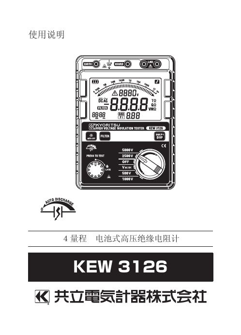
测试范围
输出电压 额定测试电流 短路电流 允许误差
电压监控(绝缘电阻量程) 30~6000V(分辨率10V) : ±10%rdg±20V 此监控用于确认测试回路充电电荷的放电状态。测试时,将监控 器上显示的测试电压值作为标准值使用。请注意施加外部交流电压 时的显示值并非正确值。
— 5 —
— 4 —
3.规格
●适用规格 IEC 61010-1 IEC 61010-031 IEC 61326-2-2 IEC 60529 測定CAT.Ⅲ 600V 污染度2 手持型探棒规格 EMC规格 IP保护等级40
●测试范围及允许误差(温湿度 23±5℃ 45 ~ 75% RH) 【绝缘电阻计】 额定测试电压 500V 1000V 2500V 5000V 0.0~99.9MΩ 0.0~99.9MΩ 0.0~99.9MΩ 0.0~99.9MΩ 100~999MΩ 100~999MΩ 100~999MΩ 100~999MΩ 1.00~1.99GΩ 1.00~9.99GΩ 1.00~9.99GΩ 10.0~99.9GΩ 10.0~99.9GΩ 100~1000GΩ DC 500V DC 1000V DC 2500V DC 5000V +30%, -0% +20%, -0% +20%, -0% +20%, -0% 5MΩ时 2.5MΩ时 1MΩ时 0.5MΩ时 1mA以上1.2mA 1mA以上1.2mA 1mA以上1.2mA 1mA以上1.2mA 以下 以下 以下 以下 最大短路电流5mA 100GΩ以上 ±5%±3dgt ±20%rdg
— 1 —
危险 ●请勿在对地电压AC/DC600V以上回路中使用。 ●请勿在易燃性环境中测试。可能会产生火花引起爆炸。 ●仪器或手潮湿时请勿使用。 ● 测试电压时请勿使测试线金属头部与电源线短路。可能导致人 身伤害事故。 ●测试时,请勿超量程输入。 ●连接测试线时,请勿按测试键。 ●测试中,请勿打开电池盖。 ● 绝缘电阻测试中和测试完成后,请勿立刻碰触被测回路。存在 的测试电压可能导致触电事故。
- 1、下载文档前请自行甄别文档内容的完整性,平台不提供额外的编辑、内容补充、找答案等附加服务。
- 2、"仅部分预览"的文档,不可在线预览部分如存在完整性等问题,可反馈申请退款(可完整预览的文档不适用该条件!)。
- 3、如文档侵犯您的权益,请联系客服反馈,我们会尽快为您处理(人工客服工作时间:9:00-18:30)。
● 测试前,使用高压电流仪确认被测回路中无电荷。 ● 必须戴上高压绝缘手套。 ● 绝缘电阻量程时,按测试开关后测试线头部和被测回路中产生高压电,请注意避免触摸。 ● 电池盖打开时,请不要进行测量。 ● 打雷时,请不要进行测量。
注意 显示带电线路警告或蜂鸣器发出警告声时,即使按下测试开关也不能进行测量。 使用本仪器可检查电气设备或电路的绝缘状况。测量时,请确认施加于被测回路的电压是否良好。 (注意) * 由于被测物不同,其绝缘电阻值可能不稳定,而可能造成显示的电阻值也不稳定。
电池电压在操作电压下限以下,不能保证精确度。更换方法请参考 8 章。 5-2 连接测试线
将测试线稳固插入仪器端口,测试线(红色)连接到测试端口,接地线(黑色)连接到接地端口和保护线(绿色)连接到保护 端口。
危险 ● 绝缘测量量程时按下测试开关后,测试线产生高压电,若碰触可能导致触电事故。
-3-
6. 测量
5000V
0.0~99.9MΩ 100~999MΩ 1.00~9.99GΩ 10.0~99.9GΩ 100~1000GΩ
DC 5000V +20%,-0% 5MΩ 负荷时 1mA—1.2mA
30~600V(分辨率 10V): ±10%rdg±10dgt
此模式适用于确认被测物中充电电荷的放电状态。测量时,将监视器中显示的测量电压值做为标准使用。请注意外部施加交流电压
●精确度保证温湿度范围: 23ºC±5ºC/相对湿度 85%以下(无结露)
●操作温度与湿度范围: 0ºC-40ºC /相对湿度 85% 以下(无结露)
●存储温度与湿度范围: -20ºC-60ºC /相对湿度 75% 以下(无结露)
●过载保护: 绝缘抵抗范围: AC1200V/10 秒。
电 压 范 围: AC720V/10 秒。
必须严格遵守上述操作说明。 如不遵守,测量时可能会导致人身伤害和仪器毁坏。
本仪器上的标志 意思是指为了安全操作本仪器,请使用者参照使用手册的相关部分操作。 危险 表示操作不当会导致严重或致命的伤害。 警告 表示操作不当存在导致严重或致命的伤害的可能性。 注意 表示操作不当有可能会导致人身伤害或仪器毁坏。
1000mA/5M Ω 120mA
25mA
AC.V 110mA ( 电 压 测 量时)
110mA
●测量时间: 约 10 小时/电池电压:9.0V: 绝缘电阻 5000V 量程 100 MΩ 时
●附 件: 测试线组合 M-7164(M- 节
使用说明书
+ 30% ,-0% + 20%,-0%
0.5MΩ 负荷时 1MΩ 负荷时
1mA--1.2mA 1mA--1.2mA
DC 2500V + 20%,-0% 2.5MΩ 负荷时 1mA--1.2mA
短路电流
约 1.3mA
精确度 ±5%rdg±3%dgt / ±20%(100GΩ 以上)
电压监视器(绝缘电阻量程)
●低电池警告: 电池图(4 格)
●超量程指示: “OL”标记(绝缘电阻量程)
“Hi”标记(电压量程)
-1-
●自动量程: 较高的范围: 1000 计数
较低的范围: 80 计数(仅绝缘阻抗量程)
●采样率: 约 0.5--5 次/秒。
●自动关机功能: 操作后 10 分钟自动关机(消耗电流约 1µA)
●使用环境条件: 海拔 2000m 以下
在任意两点时间里,根据设定自动测量电阻比率。
3. 技术规格
● 应用标准
IEC 61010-1 CAT.III 600V 污染度 2
CAT.I 5000V 污染度 2
IEC 61010-031 (手持式探针要求标准)
IEC 61326-1 EMC 标准
IEC 60529
IP40
● 测量范围和精确度(温度/湿度: 23±5ºC,45~75%RH)
-0-
2. 特点
MODEL3125 是由电子控制的 4 个量程测量绝缘电阻的高压绝缘电阻计。 ● 设计达到以下安全标准:
IEC 61010-1(CAT.III 600V 污染度 2) IEC 61010-031(手持式探针要求标准) ● 自动放电功能:测试电容性负荷的绝缘电阻时,测量后自动释放充电电荷。放电状态可在电压模式中确认。 ● 背光功能便于在阴暗光线或夜间工作。 ● 条形图显示测量结果。 ● 带电线路警告标志和蜂鸣警告。 ● 自动关机功能:为避免忘记关机造成的电池浪费,测量后 10 分钟无操作时仪器将自动关机。 ● 设定测试时间功能:在指定时间里自动执行测量。 ● PI 测量(极化指数测量):
-4-
注意:必须关闭断路器。 (5) 仪器配备自动放电功能。测量完成后,请勿取下测试线,放开测试开关,让仪器自动释放测试时产生的电压。此时,请确认
电压监视器上的显示是“0V”。 危险
* 测试以后请勿立刻触摸电路。存储的电荷可能导致触电事故。 * 请勿立刻取下测试线,必须等放电完成后再碰触被测回路。 <自动放电功能>` 是测量完成后自动释放充电电荷的功能。放电状态可在电压监视器中确认。放电完成前,移开测试线 2 秒以上,可解除放电 功能。 (6) 切换到“OFF”位置,取下测试线。 (注意) “OFF”以外的量程,不测量时仍需消耗 25mA 的电流(自动关机约 1µA)。 不使用仪器时,请切换到“OFF”位置。(自动关机功能 请参考 6-9) 绝缘电阻的测量原理 电阻(绝缘电阻)上施加一定高电压,获得流动电流值后可计算电阻值。
警告 ● 若仪器出现异常请停止使用。例如:仪器破损或裸露出金属部分。 ● 测试导线连接被测回路时,不要旋转功能选择开关。 ● 请勿对仪器安装替代部件或进行任何未授权的改造,维修时仪器返回共立产品
中国办事处。 ● 仪器在潮湿状态下请勿更换电池。 ● 确定所有测试导线与仪表的测试端口连接牢固。 ● 打开电池盖时,确保仪器已关机。
6-1 断电确认(电压测量) 危险
˔ 为避免触电事故,请勿在对地电压 AC/DC 大于 600V 的回路中测量。即使线间 电压在 600V 以下,对地电压高于 600V 也不能测量。
˔ 测量大电流电力线的电压时,必须在断路器的次级回路中测量,否则可能导致人身伤害事 故。
˔ 电压测量时请注意避免测试线金属部分和回路的短路,可能导致触电事故。 ˔ 电池盖打开时,请不要进行测量。
量程
500V
1000V
2500V
输 出 短 路 220mA 时
220mA
220mA
额 定 电 流 650mA/0 700mA/1M 800mA/2.5
输出时
.5MΩ
Ω
MΩ
输 出 开 放 40mA 时
50mA
80mA
待机时
25mA
25mA
25mA
背 光 灯 点 增加 35mA 亮时
5000V 220mA
安全警告
本仪器的设计、制造和检测均达到 IEC61010 安全标准(电子类测量产品安全要求),本说明书包括确保仪器的安全使用及保证仪 器的安全状态,使用者所必须遵守的警告和安全条例。使用前请先阅读以下说明。
警告 ● 使用前,通读并理解说明书中的操作指南。 ● 请将说明书随身保存以确保可随时参阅。 ● 必须按指示使用仪器。 ● 理解并遵守安全操作指示。
●耐 电 压: AC8320V(50/60Hz)/5 秒 (电路与外箱间)
●绝缘阻抗: ≥1000MΩ/ DC 1000V (电路与外箱间)
●尺 寸: 152(L)×205(W)×94(D)mm
●重 量: 1.8kg(含电池)
●电 源: DC12V: 碱性电池(LR14) × 8 节
˔ 电流消耗: 约 1A(最大) (平时约 25mA)
使用说明
数字式高压绝缘电阻测试仪
MODEL 3125
目录 1.安全警告 2.特点 3.技术规格 4.仪器布局
4-1 仪器布局 4-2 液晶屏显示 5. 测试前的准备 5-1 检查电池电压 5-2 连接测试导线 6. 测试 6-1 电压测量 6-2 绝缘电阻的测量 6-3 连续测量 6-4 定时器测量功能 6-5 极化指数测量 6-6 测量端口的电压特性 6-7 保护接线的使用 6-8 背光功能 6-9 自动关机功能 7.电池更换 8、附件 8-1 测试探棒的金属部分和更换 8-2 记录仪适配器 8-3 鳄口夹测试线
将电压量程开关设置到“AC.V”位置可测量电压。测量时,无须按测试按钮。 仪器装备有 AC/DC 自检电路,测量直流电压。 直流电压测量中,测试线(红)为正电压时,显示“+”标志。 必须关闭断路器。 (1) 接地线(黑)连接被测回路的接地端,测试线(红)连接测试端口。 (2) 确认液晶屏上电压显示为“0V”。 若不是“0V”标志,则被测回路中存在电压。请再次检查被测回路中的断路器是否关闭。
* 绝缘阻抗测试期间可能发出哔哔声,并非故障。 * 测量电容的负需花时间。 * 绝缘电阻测量时,测试端口电压从接地端正极(+)到测试端负极(-)输出。测量时,接地测试线连接接地端,一般来说,对地的绝
缘测量、被测物一端接地时,接地端连接正极(+)的方法所测得的电阻值较小,最适用于检测绝缘不良现象。 (1) 确认被测回路电压良好,将量程开关切换到需要的绝缘电阻范围。 (2) 接地线(黑)连接回路接地端。 (3) 测试线(红)头部接触被测电路,按下测试按钮。测量中,间歇地发出蜂鸣声音(500V 除外)。 (4) LCD 显示测量值。测量后显示值固定不变。
1 绝缘电阻 3 电压 5 低电量警告 7 定时器标记 9 定时器 2 标记 11 直流 13 负显示
2 条形图 4 电池标志 6 定时器显示 8 定时器 1 标记 10 PI 标记 12 交流 14 单位
5. 测量前的准备
5-1 检查电池电压 (1) 量程范围开关切换至 “OFF”外的任何位置。. (2) 显示屏左上的电池标记为 时,表示电池量剩余不多,请更换新电池后继续测量。此状态中并不影响精确度。电池标记为 时,